
User Manual


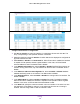
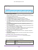

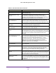
Table Of Contents
- M6100 Web Management User Guide
- Contents
- 1. Getting Started
- 2. Configuring System Information
- 3. Configuring Switching Information
- 4. Routing
- 5. Configuring Quality of Service
- 6. Managing Device Security
- 7. Monitoring the System
- 8. Maintenance
- 9. Help
- A. Default Settings
- B. Configuration Examples
- C. Notification of Compliance

Routing
231
M6100 Web Management User Guide
Note: When the configuration method is changed from DHCP to None there
will be a minor delay before the page refreshes.
5. Use IP Address to enter the IP address for the interface.
6. Use Subnet Mask to enter the subnet mask for the interface. This is also referred to as the
subnet/network mask, and defines the portion of the interface's IP address that is used to
identify the attached network.
7. Use Routing Mode to enable or disable routing for an interface. The default value is enable.
8. Use Administrative Mode to enable/disable the Administrative Mode of the interface. The
default value is enable. This mode is not supported for Logical VLAN Interfaces.
9. Use Forward Net Directed Broadcasts to select how network directed broadcast packets
should be handled. If you select enable from the menu, network directed broadcasts will be
forwarded. If you select disable they will be dropped. The default value is disable.
10. Use Encapsulation Type to select the link layer encapsulation type for packets transmitted
from the specified interface from the menu. The possible values are Ethernet and SNAP.
The default is Ethernet.
11. Use Proxy Arp to disable or enable proxy Arp for the specified interface from the menu.
12. Use Local Proxy Arp to disable or enable Local Proxy ARP for the specified interface from
the menu.
13. Use Bandwidth (kbps) to specify the configured bandwidth on this interface. This
parameter communicates the speed of the interface to higher level protocols. OSPF uses
bandwidth to compute link cost. Valid range is (1 to 10000000).
14. Use ICMP Destination Unreachables to specify the Mode of Sending ICMP Destination
Unreachables on this interface. If this is Disabled then this interface will not send ICMP
Destination Unreachables. By default Destination Unreachables mode is enable.
15. Use ICMP Redirects to enable/disable ICMP Redirects Mode. The router sends an ICMP
Redirect on an interface only if Redirects are enabled both globally and on the interface. By
default ICMP Redirects Mode is enable.
16. Use IP MTU to specify the maximum size of IP packets sent on an interface. Valid range is
68 bytes to the link MTU. Default value is 0. A value of 0 indicates that the IP MTU is
unconfigured. When the IP MTU is unconfigured the router uses the link MTU as the IP
MTU. The IP MTU is the maximum frame size minus the length of the layer 2 header.
17. Click Apply to send the updated configuration to the switch. Configuration changes take
effect immediately.
18. Click Cancel to cancel the configuration on the screen and reset the data on the screen to
the latest value of the switch.
19. Click Delete to delete the IP Address from the selected interface.
20. Click Update to update the page with the latest information on the switch.
Table 85, IP Interface Configuration describes the non-configurable data that is displayed.