
User Manual
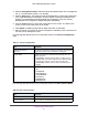
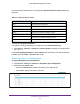
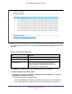
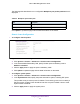
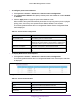
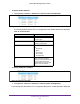
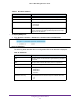
Table Of Contents
- M6100 Web Management User Guide
- Contents
- 1. Getting Started
- 2. Configuring System Information
- 3. Configuring Switching Information
- 4. Routing
- 5. Configuring Quality of Service
- 6. Managing Device Security
- 7. Monitoring the System
- 8. Maintenance
- 9. Help
- A. Default Settings
- B. Configuration Examples
- C. Notification of Compliance

Configuring System Information
85
M6100 Web Management User Guide
Figure 15. Backplane-Port Diagnostics
The following table describes the non-configurable Backplane-port Diagnostics data that is
displayed.
Table 41. Backplane-Port Diagnostics
Field Description
Unit ID The slot number of the blade.
Port Displays the backplane-port on the given blade.
Port Diagnostics Info Displays three text fields (character strings) populated by the
driver containing debug and status information.
The Port
Diagnostics information contains hardware counters; counter
values are displayed in hexadecimal digits.
Click Update to update the page with the latest information on the switch.
To display Backplane-Port Packet-Path:
1. Click System
Chassis > Advanced > Backplane-port Diagnostics to display the
Blackplane-port packet-path fields.
2. T
o navigate, select either the Unit ID or All.
• Select the Unit ID field to display the packet path starting from the selected blade.
• Select All to display the packet path starting from all the blades of the chassis.