
User Manual
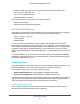
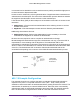
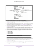
Table Of Contents
- M6100 Web Management User Guide
- Contents
- 1. Getting Started
- 2. Configuring System Information
- 3. Configuring Switching Information
- 4. Routing
- 5. Configuring Quality of Service
- 6. Managing Device Security
- 7. Monitoring the System
- 8. Maintenance
- 9. Help
- A. Default Settings
- B. Configuration Examples
- C. Notification of Compliance

Ports 1/0/1 - 1/0/5
Connected to Hosts
Ports 1/0/1 - 1/0/5
Connected to Hosts
Ports 1/0/1 - 1/0/5
Connected to Hosts
Ports 1/0/6 - 1/0/8
Connected to Switch 2 and 3
Ports 1/0/6 - 1/0/8
Connected to Switch 1 and 3
1/0/1 - 1/0/5 Switch 1
Root Bridge
Switch 2
Switch 3
Ports 1/0/6 - 1/0/8
Connected to
Switch 2 and
Configuration Examples
559
M6100 Web Management User Guide
Perform the following procedures on each switch to configure MSTP:
1. Use the VLAN Configuration screen to create VLANs 300 and 500 (see VLAN
Configuration on page 137).
2. Use the VLAN Membership screen to include ports 1/0/1 - 1/0/8 as tagged (T) or untagged
(U) members of VLAN 300 and VLAN 500 (see VLAN Configuration on page 137).
3. From the STP Configuration screen, enable the Spanning
Tree State option (see STP
Configuration on page 158).
Use the default values for the rest of the STP configuration settings. By default, the STP
Operation Mode is MSTP and the Configuration Name is the switch MAC address.
4. From the CST Configuration screen, set the Bridge Priority value for each of the three
switches to force Switch 1 to be the root bridge:
• Switch 1: 4096
• Switch 2: 12288
• Switch 3: 20480
Note: Bridge priority values are multiples of 4096.
If you do not specify a root bridge and all switches have the same Bridge Priority value,
the switch with the lowest MAC address is elected as the root bridge (see CST
Configuration on page 162).
5. From the CST Port Configuration screen, select ports 1/0/1 - 1/0/8 and select Enable from
the STP Status menu (see CST Port Configuration on page 164).
6. Click Apply.