
User Manual
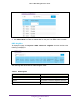
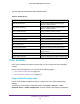
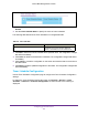
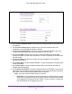
Table Of Contents
- M6100 Web Management User Guide
- Contents
- 1. Getting Started
- 2. Configuring System Information
- 3. Configuring Switching Information
- 4. Routing
- 5. Configuring Quality of Service
- 6. Managing Device Security
- 7. Monitoring the System
- 8. Maintenance
- 9. Help
- A. Default Settings
- B. Configuration Examples
- C. Notification of Compliance

130
3
3. Configuring Switching Information
Use the features in the Switching tab to define Layer 2 features. The Switching tab contains links
to the following features:
• VLANs on page 130
• Auto-VoIP on page 144
• iSCSI on page 148
• Spanning Tree Protocol on page 152
• Multicast on page 166
• MVR Configuration on page 182
• Address Table on page 188
• Ports on page 192
• Port Transceiver on page 195
• Multiswitch Link Aggregation Group on page 200
VLANs
Adding Virtual LAN (VLAN) support to a Layer 2 switch offers some of the benefits of both
bridging and routing. Like a bridge, a VLAN switch forwards traffic based on the Layer 2
header, which is fast, and like a router, it partitions the network into logical segments, which
provides better administration, security and management of multicast traffic.
By default, all ports on the switch are in the same broadcast domain. VLANs electronically
separate ports on the same switch into separate broadcast domains so that broadcast
packets are not sent to all the ports on a single switch. When you use a VLAN, users can be
grouped by logical function instead of physical location.
Each VLAN in a network has an associated VLAN ID, which appears in the IEEE 802.1Q tag
in the Layer 2 header of packets transmitted on a VLAN. An end station may omit the tag, or
the VLAN portion of the tag, in which case the first switch port to receive the packet may
either reject it or insert a tag using its default VLAN ID. A given port may handle traffic for
more than one VLAN, but it can only support one default VLAN ID.
From the VLAN link, you can access the following pages:
• Basic on page 131