
User Manual
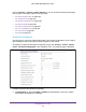

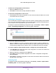
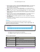
Table Of Contents
- M6100 Web Management User Guide
- Contents
- 1. Getting Started
- 2. Configuring System Information
- 3. Configuring Switching Information
- 4. Routing
- 5. Configuring Quality of Service
- 6. Managing Device Security
- 7. Monitoring the System
- 8. Maintenance
- 9. Help
- A. Default Settings
- B. Configuration Examples
- C. Notification of Compliance

Managing Device Security
463
M6100 Web Management User Guide
2. HTTP traffic uses standard port 80, but you can use the Additional HTTP Port field to
configure an additional port for HTTP traffic. Enter a port number between 0-65535
(excluding port 80). Enter 0 to unconfigure the Additional HTTP Port. The default is 0.
3. HTTP Secure traf
fic uses standard port 443, but you can configure an additional port for
HTTP Secure traffic using the Additional HTTP Secure Port field. Enter a port number
between 0-65535 (excluding port 443). Enter 0 to unconfigure the Additional HTTP Secure
Port. The default is 0.
4. T
o access the network through a portal, the client must first enter authentication information
on an authentication Web page. Use the Authentication Timeout field to enter the number
of seconds that captive portal keeps the authentication session open with a client that is
attempting to access the network through a portal. When the timeout expires, the switch
disconnects any active TCP or SSL connection with the client. The valid range is 60 to 600
seconds. The default Authentication Timeout is 300 seconds.
5. Click Apply to send the updated configuration to the switch. Configuration changes take
ef
fect immediately.
6. Click Cancel to cancel the configuration on the screen and reset the data on the screen to
the latest value of the switch.
Table 158, Captive Portal Global Configuration on page 463 describes the non-configurable
data that is displayed.
Table 158. Captive Portal Global Configuration
Field Description
Operational Status The operational status of the captive portal feature, which is either
Enabled or Disabled.
The default is Disabled.
Disabled Reason If CP is disabled, this field displays the reason, which can be one of the
following:
• Administratively disabled
• IP address not configured
• No IP routing interface
• Routing disabled
CP IP Address The IP address that the captive portal uses.
Supported Captive Portals Displays the number of supported captive portals in the system.
Configured Captive Portals Shows the number of captive portals configured on the switch.
Active Captive Portals Shows the number of captive portal instances that are operationally
enabled.
System Supported Users Shows the number of authenticated users that the system can support.
Local Supported Users Shows the number of entries that the Local User database supports.
Configured Local Users The number of local users configured.
Authenticated Users Shows the number of users currently authenticated to all captive portal
instances on this switch.