
User Manual
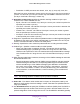
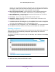


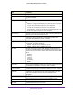

Table Of Contents
- M6100 Web Management User Guide
- Contents
- 1. Getting Started
- 2. Configuring System Information
- 3. Configuring Switching Information
- 4. Routing
- 5. Configuring Quality of Service
- 6. Managing Device Security
- 7. Monitoring the System
- 8. Maintenance
- 9. Help
- A. Default Settings
- B. Configuration Examples
- C. Notification of Compliance

Monitoring the System
499
M6100 Web Management User Guide
Field Description
MST ID Display the MST instances associated with the interface.
ifIndex This object indicates the ifIndex of the interface table entry associated with
this port on an adapter.
Port Type For normal ports this field will be ‘normal.’ Otherwise the possible values
are:
• Mirrored - This port is a participating in port mirroring as a mirrored port.
Look at the Port Mirroring screens for more information.
• Probe - This port is a participating in port mirroring as the probe port.
Look at the Port Mirroring screens for more information.
• Trunk Member - The port is a member of a Link Aggregation trunk. Look
at the Port Channel screens for more information.
Port Channel ID If the port is a member of a port channel, the port channel's interface ID and
name are shown. Otherwise “Disable” is shown.
Port Role Each MST Bridge Port that is enabled is assigned a Port Role for each
spanning tree. The port role will be one of the following values: Root,
Designated, Alternate, Backup, Master, or Disabled.
STP Mode The Spanning Tree Protocol Administrative Mode associated with the port or
Port Channel. The possible values are:
• Enable - Spanning tree is enabled for this port.
• Disable - Spanning tree is disabled for this port.
STP State The port's current Spanning Tree state. This state controls what action a
port, takes on receipt of a frame. If the bridge detects a malfunctioning port it
will place that port into the broken state. The five states are defined in IEEE
802.1D:
• Disabled
• Blocking
• Listening
• Learning
• Forwarding
• Broken
Admin Mode The Port control administration state. The port must be enabled in order for it
to be allowed into the network. The factory default is enabled.
Flow Control Mode Indicates whether flow control is enabled or disabled for the port. This field is
not valid for Lag interfaces.
LACP Mode Indicates the Link Aggregation Control Protocol administration state. The
mode must be enabled in order for the port to participate in Link
Aggregation.
Physical Mode Indicates the port speed and duplex mode. In auto-negotiation mode the
duplex mode and speed are set from the auto-negotiation process.
Physical Status Indicates the port speed and duplex mode.
Link Status Indicates whether the Link is up or down.