
User Manual


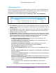


Table Of Contents
- M6100 Web Management User Guide
- Contents
- 1. Getting Started
- 2. Configuring System Information
- 3. Configuring Switching Information
- 4. Routing
- 5. Configuring Quality of Service
- 6. Managing Device Security
- 7. Monitoring the System
- 8. Maintenance
- 9. Help
- A. Default Settings
- B. Configuration Examples
- C. Notification of Compliance

Configuring Switching Information
196
M6100 Web Management User Guide
Table 75 describes the non-configurable data that is displayed.
Table 75.
Field Description
Port Displays the interface for which data is to be
displayed.
Vendor Name Vendor name of the SFP.
Link Length 50 μm Link length supported for 50 μm fiber
.
Link Length 62, 5 μm Link length supported for 50 μm fiber
.
Serial Number Serial number of the SFP.
Part Number Part number of the SFP.
Nominal Bit Rate Nominal signalling rate for SFP.
Revision Vendor revision of the SFP.
Compliance Compliance of the SFP.
Port Transceiver
Click Update to update the page with the latest information on the switch.
Link Aggregation Groups
Link aggregation groups (LAGs), which are also known as port-channels, allow you to
combine multiple full-duplex Ethernet links into a single logical link. Network devices treat the
aggregation as if it were a single link, which increases fault tolerance and provides load
sharing. You assign the LAG VLAN membership after you create a LAG. The LAG by default
becomes a member of the management VLAN.
A LAG interface can be either static or dynamic, but not both. All members of a LAG must
participate in the same protocols.
A static port-channel interface does not require a partner
system to be able to aggregate its member ports.
Static LAGs are supported. When a port is added to a LAG as a static member, it neither
transmits nor receives LACPDUs.
From the LAGs link, you can access the following pages:
• LAG Configuration on page 197
• LAG Membership on page 198