
User Manual


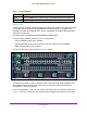
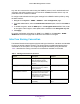
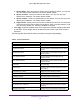

Table Of Contents
- M6100 Web Management User Guide
- Contents
- 1. Getting Started
- 2. Configuring System Information
- 3. Configuring Switching Information
- 4. Routing
- 5. Configuring Quality of Service
- 6. Managing Device Security
- 7. Monitoring the System
- 8. Maintenance
- 9. Help
- A. Default Settings
- B. Configuration Examples
- C. Notification of Compliance

Getting Started
15
M6100 Web Management User Guide
Any user can connect to the switch using the SNMPv3 protocol, but for authentication and
encryption, the switch supports only one user which is admin; therefore there is only one
profile that can be created or modified.
To configure authentication and encryption settings for the SNMPv3 admin profile by using
the W
eb interface:
1. Navigate to the System SNMP SNMPv3 User Configuration page.
2. T
o enable authentication, select an Authentication Protocol option, which is either MD5 or
SHA.
3. T
o enable encryption, select the DES option in the Encryption Protocol field. Then, enter
an encryption code of eight or more alphanumeric characters in the Encryption Key field.
4. Click Apply.
To access configuration information for SNMP V1 or SNMP V2, click System
SNMP
SNMPv1/v2 and click the page that contains the information to configure.
Interface Naming Convention
The M6100 Chassis switch supports physical and logical interfaces. Interfaces are identified
by their type and the interface number. The physical ports are gigabit interfaces and are
numbered on the front panel. You configure the logical interfaces by using the software.
Table 3 describes the naming convention for all interfaces available on the switch.
Table 3. Naming Conventions for Interfaces
Interface Description Example
Physical The physical ports are gigabit
Ethernet interfaces and are
numbered sequentially starting
from one.
0/1, 0/2, 0/3, and so on
Link Aggregation Group (LAG) LAG interfaces are logical
interfaces that are only used for
bridging functions.
lag 1, lag 2, lag 3, and so on
CPU Management Interface This is the internal switch interface
responsible for the switch base
MAC address.
This interface is not
configurable and is always listed in
the MAC Address Table.
5/1
Routing VLAN Interfaces This is an interface used for routing
functionality
.
VLAN 1, VLAN 2, VLAN 3, and
so on