
Owner's Manual


Chapter 27. Multicast Routing and Switching | 747
NETGEAR 8800 User Manual
enable ipmcforwarding comm._vlan
configure ospf add vlan comm._vlan area 0.0.0.0
enable ospf
PIM Snooping Example Configuration Displays
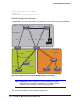
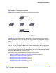
After the example configuration is complete, multicast receivers connect to the network
through switch S5 and multicast sources connect through switch S3.
When switch S5 receives an IGMP request from the receiver_vlan for group 225.1.1.1, it
sends a PIM (*,
G) join towards switch S3, which is the RP. The PIM snooping feature on
switch S1 snoops the (*,
G) join, and the resulting entry can be viewed by entering the
following command at switch S1:
show pim snooping vlan comm_vlan
PIM Snooping ENABLED
Vlan comm_vlan(3971) Snooping ENABLED
Source Group RP UpPort DownPort Age HoldTime
* 225.1.1.1 10.172.169.4 1 2 15 210
Neighbor IP DR Port Age Hold Time
10.1272.168.4 YES 1 2 105
10.1272.168.2 NO 2 2 105
10.1272.168.3 NO 3 2 105
Once multicast traffic arrives from the sender_vlan, the LHR (switch S2) sends the (S, G) join
message, which is snooped by the PIM snooping switch, switch S1. The resulting entries can
be viewed by entering the following command at switch S1:
show pim snooping vlan comm_vlan
PIM Snooping ENABLED
Vlan comm_vlan(3971) Snooping ENABLED
Source Group RP UpPort DownPort Age HoldTime
* 225.1.1.1 10.172.169.4 1 2 15 210
10.172.169.10 225.1.1.1 10.172.169.4 1 2 15 210
Neighbor IP DR Port Age Hold Time
10.1272.168.4 YES 1 2 105
10.1272.168.2 NO 2 2 105
10.1272.168.3 NO 3 2 105
Multicast traffic is forwarded only to those ports that have received (*, G) or (S, G) joins and
designated router (DR) ports.