
Owner's Manual


Chapter 25. OSPFv3 | 695
NETGEAR 8800 User Manual
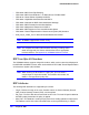
Figure 79. OSPFv3 Configuration Example
In Figure 79 there are three NETGEAR switches running XCM8800 images that have
support for OSPFv3. Router 1 is an area border router and is connected to two other
switches Router 2 and Router 3. Router 1 runs OSPFv3 on both the links connecting it to
Router 2 and Router 3.
The router configurations for the example in Figure 79 are provided in the following section.
After doing all the configurations, Router 1 will establish OSPFv3 adjacency with Router 2
and Router 3. They will also exchange the various link state databases.
Configuration for Router 1
The router labeled Router 1 has the following configuration:
create vlan to-r2
create vlan to-r3
configure vlan to-r2 ipaddress 2001:db8:4444:6666::1/64
configure vlan to-r3 ipaddress 2001:db8:3333:5555::1/64
configure vlan to-r2 add port 1:1
configure vlan to-r3 add port 1:2
enable ipforwarding ipv6
configure ospfv3 routerid 0.0.0.1
configure ospfv3 add vlan to-r2 area 0.0.0.0
Area 0.0.0.0
Area 0.0.0.1
Router 2
Router 1
Router 3
EX_107
2001:db8:4444:6666::2/64
2001:db8:4444:6666::1/64
2001:db8:3333:5555::1/64
2001:db8:3333:5555::2/64
to-r2
to-r3