
Owner's Manual


Chapter 19. VRRP | 591
NETGEAR 8800 User Manual
The configuration commands for switch B are as follows:
configure vlan vlan1 ipaddress 192.168.1.5/24
create vrrp vlan vlan1 vrid 1
configure vrrp vlan vlan1 vrid 1 add 192.168.1.3
enable vrrp
Fully Redundant VRRP Network
You can use two or more VRRP-enabled switches to provide a fully redundant VRRP
configuration on your network.
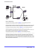
Figure 60 shows a fully redundant VRRP configuration.
Figure 60. Fully Redundant VRRP Configuration
In Figure 60, switch A is configured as follows:
• IP address 192.168.1.3
• Master router for VRID 1
• Backup router for VRID 2
• MAC address 00-00-5E-00-01-01
Switch B is configured as follows:
• IP address 192.168.1.5
• Master router for VRID 2
• Backup router for VRID 1
• MAC address 00-00-5E-00-01-02
Both virtual routers are simultaneously operational. The traffic load from the four hosts is split
between them. Host 1 and host 2 are configured to use VRID 1 on switch A as their default
gateway. Host 3 and host 4 are configured to use VRID 2 on switch B as their default
EX_069
Default Route
Switch A
Master for virtual IP 192.168.1.3
Master VRID = 1
Backup for virtual IP 192.168.1.5
Backup VRID = 2
MAC address = 00-00-5E-00-01-01
Switch B
Master for virtual IP 192.168.1.5
Master VRID = 2
Backup for virtual IP 192.168.1.3
Backup VRID = 1
MAC address = 00-00-5E-00-01-02
Backup Route