
Owner's Manual


Chapter 18. STP | 579
NETGEAR 8800 User Manual
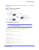
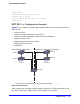
Figure 58. MSTP Configuration Example
For MSTP to work, complete the following steps on all switches in Region 1 and Region 2:
• Remove ports from the VLAN Default that will be added to VLAN Engineering.
• Create the VLAN Engineering.
• Assign a VLAN ID to the VLAN Engineering.
Note: If you do not explicitly configure the VLAN ID in your MSTP deployment,
use the show vlan command to see the internal VLAN ID automatically
assigned by the switch.
• Add ports to the VLAN Engineering.
• Create the MSTP region.
Note: You can configure only one MSTP region on the switch at any given
time.
• Create the STPD to be used as the CIST, and configure the mode of operation for the
STPD.
• Specify the priority for the CIST.
• Enable the CIST.
• Create the STPD to be used as an MSTI and configure the mode of operation for the
STPD.
• Specify the priority for the MSTI.
• Assign the VLAN Engineering to the MSTI.
EX_166
9
Switch A
= boundary port
= master port
= MSTI root port
12
3
45 67
108
CIST regional root
MSTI regional root
Switch F
MSTI regional root
STPD SI configured on switch A-C
VLAN engineering assigned to SI
STPD SI configured on switch E-G
VLAN finance assigned to SI
CIST regional root
CIST root port
CIST root
Switch D
Switch B Switch C
MSTP
Region 1
MSTP
Region 2
Switch E
Switch G