
Owner's Manual


Chapter 9. VLANs | 243
NETGEAR 8800 User Manual
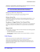
Figure 9. Physical Diagram of Tagged and Untagged Traffic
Figure 10 is a logical diagram of the same network.
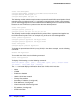
Figure 10. Logical Diagram of Tagged and Untagged Traffic
In Figure 9 and Figure 10:
• The trunk port on each switch carries traffic for both VLAN Marketing and VLAN Sales.
• The trunk port on each switch is tagged.
• The server connected to port 25 on system 1 has a NIC that supports 802.1Q tagging.
• The server connected to port 25 on system 1 is a member of both VLAN Marketing and
VLAN Sales.
• All other stations use untagged traffic.
As data passes out of the switch, the switch determines if the destination port requires the
frames to be tagged or untagged. All traffic coming from and going to the server is tagged.
Traffic coming from and going to the trunk ports is tagged. The traffic that comes from and
goes to the other stations on this network is not tagged.
Mixing Port-Based and Tagged VLANs
You can configure the switch using a combination of port-based and tagged VLANs. A given
port can be a member of multiple VLANs, with the stipulation that only one of its VLANs uses
EX_064
System 1
= Marketing
= Sales
M
S
= Tagged port
Marketing & Sales
M SMS
SS
M
M
M
M
S
S
S
S
MM
SS
SS
802.1Q
Tagged server
System 2
EW_025
*Tagged Ports
Sales
System 1
Port 25 *
Port 29 *
System 2
Slot 1, Port 1 *
Marketing
System 1
Ports 1-4 & 9-12
System 2
Slot 1, Port 2
Slot 2, Ports 1-8 & 17-24
System 1
Ports 5-8, 13-16 & 32
System 2
Slot 1, Port 3
Slot 1, Port 4
Slot 2, Ports 9-16 & 25-32