
User's Manual
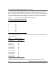

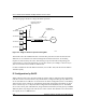


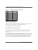
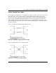

Table Of Contents
- Trademarks
- Statement of Conditions
- Federal Communications Commission (FCC) Compliance Notice: Radio Frequency Notice
- Canadian Department of Communications Compliance Statement
- CE Declaration of Conformity
- Contents
- Chapter 1 About This Manual
- Chapter 2 Introduction
- Chapter 3 Basic Installation and Configuration
- Observing Placement and Range Guidelines
- Default Factory Settings
- Understanding WG602 v2 Wireless Security Options
- Installing the 54 Mbps Wireless Access Point WG602 v2
- Two Ways to Log In to the WG602 v2
- Using the Basic IP Settings Options
- Understanding the Basic Wireless Settings
- Understanding Wireless Security Options
- How to Configure WEP Wireless Security
- How to Configure WPA-PSK Wireless Security
- How to Restrict Wireless Access by MAC Address
- Chapter 4 Management
- Chapter 5 Advanced Configuration
- Chapter 6 Troubleshooting
- Troubleshooting
- No lights are lit on the access point.
- The Ethernet LAN light is not lit.
- The Wireless LAN activity light is not lit.
- I cannot configure the wireless access point from a browser.
- I cannot access the Internet or the LAN with a wireless capable computer.
- When I enter a URL or IP address I get a timeout error.
- Using the Reset Button to Restore Factory Default Settings
- Troubleshooting
- Appendix A Specifications
- Appendix B Wireless Networking Basics
- Appendix C Network, Routing, Firewall, and Cabling Basics
- Appendix D Preparing Your PCs for Network Access
- Glossary
- Index

User’s Guide for the WG602 54 Mbps Wireless Access Point
C-14 Network, Routing, Firewall, and Cabling Basics
Figure C-3: Category 5 UTP Cable with Male RJ-45 Plug at Each End
Note: Flat “silver satin” telephone cable may have the same RJ-45 plug. However, using telephone
cable results in excessive collisions, causing the attached port to be partitioned or disconnected
from the network.
Uplink Switches, Crossover Cables, and MDI/MDIX Switching
In the wiring table above, the concept of transmit and receive are from the perspective of the PC,
which is wired as Media Dependant Interface (MDI). In this wiring, the PC transmits on pins 1 and
2. At the hub, the perspective is reversed, and the hub receives on pins 1 and 2. This wiring is
referred to as Media Dependant Interface - Crossover (MDI-X).
When connecting a PC to a PC, or a hub port to another hub port, the transmit pair must be
exchanged with the receive pair. This exchange is done by one of two mechanisms. Most hubs
provide an Uplink switch which will exchange the pairs on one port, allowing that port to be
connected to another hub using a normal Ethernet cable. The second method is to use a crossover
cable, which is a special cable in which the transmit and receive pairs are exchanged at one of the
two cable connectors. Crossover cables are often unmarked as such, and must be identified by
comparing the two connectors. Since the cable connectors are clear plastic, it is easy to place them
side by side and view the order of the wire colors on each. On a straight-through cable, the color
order will be the same on both connectors. On a crossover cable, the orange and blue pairs will be
exchanged from one connector to the other.