
Reference Manual

RF Planning and Deployment
76
ProSAFE Wireless Controller WC9500
However, the WiFi coverage tool is for display and information only. To change the actual
minimum signal strength for an RF plan, you must run the WiFi auto planning advisor again
(see Use the WiFi Auto Planning Advisor to Generate an RF Plan for a Floor on page 64).
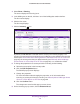
The default minimum signal strength is –62 dBm. The WiFi coverage percentage is
calculated based on this value. You can change this value and recalculate the coverage
percentage.
To display and recalculate the WiFi coverage for an existing heat map:
1. Open a web browser. In the browser’
s address field, type the wireless controller’s IP
address.
By default, the IP address is 192.168.0.250.
The wireless controller’s login screen displays.
2. Enter your user name and password.
If you did not yet personalize your user name and password, enter admin for the user
name and password for the password, both in lowercase letters.
3. Click the Login button.
The wireless controller’s web management interface opens and displays the Summary
screen.
4. Select Plans > Planning.
The screen displays the Planning icons.
5. In the building tree on the left, click the + icon of the building that contains the floor
.
The floor names display.
6. Click the floor name.
The floor map displays.
7. On the right, click the
HeatMap
icon.
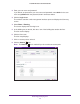
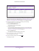
The heat map for the 2.4 GHz band is generated and displays. Use the color information
on the right as guidance for WiFi coverage.
8. To generate the heat map for the 5 GHz band, on the right, click the Band
icon.
The heat map for the 5 GHz band is generated and displays. Use the color information on
the right as guidance for WiFi coverage.
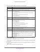
9. Click the Coverage
icon.
Note: The Coverage
icon is masked if you did not generate a heat map.