
Reference Manual


RF Planning and Deployment
65
ProSAFE Wireless Controller WC9500
Note: The antenna gain and maximum number of supported clients for a
selected access point are set automatically.
• Percentage of expected WiFi coverage (from 10 percent to 100 percent)
• The minimum required signal strength (from –95 dBm to –30 dBm)
The signal strength determines the automatic channel allocation and automatic
transmission power of the access points.
• The WiFi band (2.4 GHz or 5 GHz)
• The maximum number of clients that must be supported on the floor
For you to determine the expected financial investment, the WiFi auto planning advisor also
lets you enter a price for the selected access point and a price for the selected antenna.
Whether or not you enter a price, the WiFi auto planning advisor generates an inventory list.
For more information, see Display or Change the WiFi Inventory for an RF Plan on page 77.
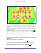
The WiFi auto planning advisor creates a heat map for the 2.4 GHz band, the 5 GHz band, or
for both bands. T
o optimize the WLAN network coverage and throughput for your RF plan,
you can manually fine-tune the placement of access points and antennas on the floor map.
For more information about adding and managing access points and antennas on a floor
map, see the following sections:
• Manually Add and Manage Access Points on a Floor Map for an RF Plan on page 69
• Manually Add and Manage Antennas on a Floor Map for an RF Plan on page 72
WARNING:
For each floor, you can save one floor map only. When you run the
WiFi auto planning advisor for a floor, the advisor removes all
previously placed access points and antennas from the floor map.
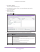
To run the WiFi auto planning advisor and generate an RF plan and heat map for a
floor:
1. Open a web browser. In the browser’s address field, type the wireless controller’s IP
address.
By default, the IP address is 192.168.0.250.
The wireless controller’s login screen displays.
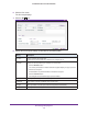
2. Enter your user name and password.
If you did not yet personalize your user name and password, enter admin for the user
name and password for the password, both in lowercase letters.
3. Click the Login button.
The wireless controller’s web management interface opens and displays the Summary
screen.