ProSAFE Wireless Controller WC9500 Reference Manual January, 2015 202-11224-05 350 East Plumeria Drive San Jose, CA 95134 USA
ProSAFE Wireless Controller WC9500 Support Thank you for selecting NETGEAR products. After installing your device, locate the serial number on the label of your product and use it to register your product at https://my.netgear.com. You must register your product before you can use NETGEAR telephone support. NETGEAR recommends registering your product through the NETGEAR website. For product updates and web support, visit http://support.netgear.com. Phone (US & Canada only): 1-888-NETGEAR.
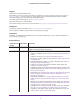
ProSAFE Wireless Controller WC9500 202-11224-04 (continued) January 2015 (continued) Added the following features: (continued) • Capability to locate and monitor an active WiFi client on a deployed floor plan (see View the Clients in the Network, View Clients on Access Points that the Wireless Controller Manages, and Monitor Local Clients in the Network) • Support for extended storage (see Manage External Storage) 202-11224-03 January 2014 Added the following features: • Support for additional access
Contents Chapter 1 Introduction Key Features and Capabilities . . . . . . . . . . . . . . . . . . . . . . . . . . . . . . . . . . . . . . . . . .12 Package Contents. . . . . . . . . . . . . . . . . . . . . . . . . . . . . . . . . . . . . . . . . . . . . . . . . . . .14 Hardware Features . . . . . . . . . . . . . . . . . . . . . . . . . . . . . . . . . . . . . . . . . . . . . . . . . . .14 Front Panel Ports, Slots, and LEDs. . . . . . . . . . . . . . . . . . . . . . . . . . . . . . . . . . . .
ProSAFE Wireless Controller WC9500 Add a Single Floor to a Building. . . . . . . . . . . . . . . . . . . . . . . . . . . . . . . . . . . . . . 51 Scale a Floor. . . . . . . . . . . . . . . . . . . . . . . . . . . . . . . . . . . . . . . . . . . . . . . . . . . . . . 53 Add a WiFi Coverage or WiFi Noncoverage Zone to a Floor . . . . . . . . . . . . . . 54 Remove a WiFi Coverage or WiFi Noncoverage Zone from a Floor. . . . . . . . 55 Add a WiFi Building Obstacle to a Floor . . . . . . . . . . . . . . . . . .
ProSAFE Wireless Controller WC9500 Configure Log, Syslog, Alarm Notification, and Email Settings . . . . . . . . . . . . 108 Configure Log Settings . . . . . . . . . . . . . . . . . . . . . . . . . . . . . . . . . . . . . . . . . . . 108 Configure Syslog Settings . . . . . . . . . . . . . . . . . . . . . . . . . . . . . . . . . . . . . . . . . 110 Configure Alarm Notification Settings. . . . . . . . . . . . . . . . . . . . . . . . . . . . . . . 112 Configure the Email Notification Server . . . . . . . . .
ProSAFE Wireless Controller WC9500 Standalone Mode in Different Layer 3 Networks . . . . . . . . . . . . . . . . . . . . . 158 Manage the Managed AP List . . . . . . . . . . . . . . . . . . . . . . . . . . . . . . . . . . . . . . . . 163 View the Managed AP List. . . . . . . . . . . . . . . . . . . . . . . . . . . . . . . . . . . . . . . . . 163 Change Access Point Information on the Managed AP List . . . . . . . . . . . . . 165 Remove Access Points from the Managed AP List. . . . . . . . . . . . . . . . .
ProSAFE Wireless Controller WC9500 Rogue Access Point Concepts . . . . . . . . . . . . . . . . . . . . . . . . . . . . . . . . . . . . . . 213 Configure Basic Rogue Detection Settings . . . . . . . . . . . . . . . . . . . . . . . . . . . 213 Classify Rogue Access Points . . . . . . . . . . . . . . . . . . . . . . . . . . . . . . . . . . . . . . 214 Import a List of Known Access Points from a File . . . . . . . . . . . . . . . . . . . . . 216 Manage Guest Network Access. . . . . . . . . . . . . . . . . . .
ProSAFE Wireless Controller WC9500 Chapter 11 Manage Stacking and Redundancy Stacking Concepts . . . . . . . . . . . . . . . . . . . . . . . . . . . . . . . . . . . . . . . . . . . . . . . . . . 269 Configure a Stack . . . . . . . . . . . . . . . . . . . . . . . . . . . . . . . . . . . . . . . . . . . . . . . . . . 271 Remove a Wireless Controller from a Stack . . . . . . . . . . . . . . . . . . . . . . . . . . . . 273 Select Which Wireless Controller in a Stack to Configure . . . . . . . . . . . . . . .
ProSAFE Wireless Controller WC9500 Use the Reset Button to Restore Default Settings . . . . . . . . . . . . . . . . . . . . . . . 341 Resolve Problems with Date and Time . . . . . . . . . . . . . . . . . . . . . . . . . . . . . . . . . 341 Resolve Problems with Access Points . . . . . . . . . . . . . . . . . . . . . . . . . . . . . . . . . . 342 Resolve Discovery Problems . . . . . . . . . . . . . . . . . . . . . . . . . . . . . . . . . . . . . . . 342 Resolve Connection Problems. . . . . . . . . . . . . .
1. 1 Introduction This chapter includes the following sections: • Key Features and Capabilities • Package Contents • Hardware Features • WC9500 Wireless Controller System Components • Supported NETGEAR Access Points • Supported NETGEAR Antennas • What Can You Do with the WC9500 Wireless Controller? • Licenses • Maintenance and Support Note: For more information about the topics covered in this manual, visit the support website at support.netgear.com.
ProSAFE Wireless Controller WC9500 Key Features and Capabilities The NETGEAR ProSAFE Wireless Controller WC9500 is a high-capacity, secured wireless controller intended for medium- to large-sized businesses, higher education institutions, hospitals, and hotels. One standalone wireless controller with the appropriate licenses can support up to 300 access points. In a stacked configuration, one wireless controller with the appropriate licenses can support up to 200 access points.
ProSAFE Wireless Controller WC9500 • • • • Security - Identity-based security authentication with an external RADIUS or LDAP (Active Directory) server, or with an internal authentication server. - Support for nine access point profile groups (one basic and eight advanced) on one wireless controller. - Support for up to 8 profiles per access point profile group and 8 profiles per radio (therefore, dual-band access points can support up to 16 profiles in one access point profile group).
ProSAFE Wireless Controller WC9500 Package Contents The ProSAFE Wireless Controller WC9500 product package contains the following items: • ProSAFE Wireless Controller WC9500 appliance • One AC power cable • Rubber feet (four) with adhesive backing • One rack-mount kit • Straight-through Category 5 Ethernet cable • ProSAFE Wireless Controller WC9500 Installation Guide If any of the parts are incorrect, missing, or damaged, contact your NETGEAR dealer.
ProSAFE Wireless Controller WC9500 From left to right, the wireless controller’s front panel shows the following counter, LEDs, button, ports, and slots: • Digital counter. Displays the number of connected access points that are in a healthy state. • From top to bottom: - Power LED - Status LED - Fan LED - Stack Master LED These LEDs are described in Table 1 on page 15. • Reset button.
ProSAFE Wireless Controller WC9500 Table 1. LED functions (continued) LED Status Description Status LED (continued) Off The wireless controller is not receiving power. Blinking yellow Firmware is being upgraded. Fan LED Green The fans are functioning correctly. Yellow One or more fans are not functioning correctly. Green The wireless controller is functioning as the master controller in a stack. Yellow The wireless controller is functioning as a slave controller in a stack.
ProSAFE Wireless Controller WC9500 From left to right, the wireless controller’s back panel components are as follows: • • Power supply. 100–240V, 5A, 47–63 Hz power supply, which includes the following external components: - AC power socket. Attach the power cord to this socket. (The wireless controller does not provide an on/off power switch.) - Handle. The handle allows for easy removal and insertion. - LED. The LED is lit green when the power supply functions correctly.
ProSAFE Wireless Controller WC9500 The WC9500 wireless controller system supports the following NETGEAR ProSAFE access point models: • WN370 ProSAFE Wall Mount Wireless N Access Point • WNAP210v2 ProSAFE Wireless-N Access Point • WNAP320 ProSAFE Wireless-N Access Point • WND930 Outdoor Dual Band Wireless-N • WNDAP350 ProSAFE Dual Band Wireless-N Access Point • WNDAP360 ProSAFE Dual Band Wireless-N Access Point • WNDAP380R ProSAFE Dual Band Wireless-N Access Point with RFID support • WNDAP620
ProSAFE Wireless Controller WC9500 A WC9500 wireless controller system supports the following access points: • WN370 ProSAFE Wall Mounted Wireless-N Access Point - Supports concurrently 802.11b, 802.11g, and 802.11n network devices. - Supports speeds of up to 300 Mbps for 802.11n network devices. - Supports Power over Ethernet (PoE) with a power consumption that complies with the 802.3af standard. - Operates in the 2.4 GHz radio band. For product documentation and firmware, visit http://support.
ProSAFE Wireless Controller WC9500 • WNDAP360 ProSAFE Dual Band Wireless-N Access Point - Supports 802.11a, 802.11b, 802.11g, and 802.11n network devices. - Supports Power over Ethernet (PoE) with a power consumption of up to 10.51W. - Operates concurrently in the 2.4 GHz and 5 GHz radio bands. - Accepts optional antennas. For product documentation and firmware, visit http://support.netgear.com/product/WNDAP360.
ProSAFE Wireless Controller WC9500 For product documentation and firmware, visit http://support.netgear.com/product/WNDAP660. Supported NETGEAR Antennas A WC9500 wireless controller system supports the following antennas: • ANT2409 ProSAFE Indoor/Outdoor 9 dBi Omni-directional Antenna - 9 dBi omni-directional antenna for indoor or outdoor use - WiFi signal 802.11g - Frequency range 2400–2485 MHz - Maximum range 11.5 km (7.
ProSAFE Wireless Controller WC9500 • Discover Access Points in the Network and Provision IP Addresses and Firmware - Discover access points in the network. The access points can be in factory default state or functioning in standalone mode, but after discovery by the wireless controller and addition to the managed access point list, the access points become dependent (managed) access points. - Provision IP addresses to the access points.
ProSAFE Wireless Controller WC9500 • Monitor the Network and Its Components - Monitor the status of all wireless devices. View the status of the wireless controllers, access points, clients, access point profiles, and the entire network, and view network usage statistics. - Monitor network health. See which access points are healthy and which ones are down or compromised. For more information, see Chapter 12, Monitor the Wireless Network and Its Components.
2.
ProSAFE Wireless Controller WC9500 Basic and Advanced Setting Concepts You can deploy the wireless controller in a small wireless network with 10 or 20 access points or in a large wireless network with up to 600 access points. Small networks require a basic configuration, but large networks can become complex and require you to configure the advanced features of the wireless controller.
ProSAFE Wireless Controller WC9500 Before you start the configuration of your wireless controller, decide whether you can use a basic configuration (that is, follow the Basic submenus) or need to use an advanced configuration (that is, follow the Advanced submenus). Once you make your choice, configuring the wireless controller can be fairly easy if you consistently follow either the Basic submenus or the Advanced submenus.
ProSAFE Wireless Controller WC9500 Group-2 Group-3 Group-1 Group-4 2 3 4 5 6 7 Group-7 Group-8 5 GHz radio 2.4 GHz radio 1 Group-6 Group-5 8 1 Security profiles 2 3 4 5 6 7 8 Security profiles Figure 6. Advanced profile group architecture The following figure shows an example of three access point profile groups, in which the first profile group (Group-1) supports five security profiles.
ProSAFE Wireless Controller WC9500 System Planning Concepts This section includes the following subsections: • Preinstallation Planning • Before You Configure a Wireless Controller Preinstallation Planning Before you install any wireless controllers, determine the following: • Number of access points required to provide seamless coverage • Number of licenses required to cover all access points that must be managed • Number of wireless controllers required • 802.
ProSAFE Wireless Controller WC9500 packets that are sent from the wireless controller do not carry the 802.1Q header, and all untagged packets that are sent to the wireless controller are treated as management VLAN traffic. Note: Use a tagged VLAN or change the tagged VLAN ID only if the hubs and switches on your LAN support 802.1Q. If they do not, and you did not configure a tagged VLAN with the same VLAN ID on the hubs and switches in your network, IP connectivity might be lost.
ProSAFE Wireless Controller WC9500 The encryption option that you can select depends upon the authentication method that you selected. The following table lists the authentication methods available, with their corresponding encryption options: Table 3.
ProSAFE Wireless Controller WC9500 High-Level Configuration Examples This section includes the following subsections: • Single Controller Configuration with Basic Profile Group • Single Controller Configuration with Advanced Profile Groups • Stacked Controller Configuration Single Controller Configuration with Basic Profile Group A basic configuration consists of a single wireless controller that controls a collection of access points that are organized into the basic default group.
ProSAFE Wireless Controller WC9500 Single Controller Configuration with Advanced Profile Groups A more complex configuration consists of a single wireless controller that controls a collection of access points that are organized in access point profile groups and might use several profiles in each access point profile group. To set up a single wireless controller system with advanced profile groups: Step Configuration Web Management Interface Path 1.
ProSAFE Wireless Controller WC9500 Stacked Controller Configuration A stacked controller configuration can consist of up to three wireless controllers and up to 600 access points. Note: If the stack members are on different floors or in different buildings, you could configure a separate access point profile group for each building or floor. To set up a stacked controller configuration: Step Configuration Web Management Interface Path 1.
ProSAFE Wireless Controller WC9500 Step Configuration Web Management Interface Path 3. Configure the slave wireless controllers and deploy them in the network. For each slave wireless controller, configure up to eight access point profile groups, and for each access point profile in a group, do at least the following: 1. Configure an SSID for wireless access. Configuration > Profile > Advanced 2. Configure the network authentication and data encryption. 3. Assign the VLAN. 4.
ProSAFE Wireless Controller WC9500 The following illustration shows a simplified view of how you can use VLANs to segregate traffic by user category: Management VLAN 100 Ethernet traffic Internet Finance VLAN 10 Ethernet traffic Employee VLAN 20 Ethernet traffic Network printer Backend L3 switch or router Deploy the wireless controller on a trunk port if you use the internal DHCP server PoE switch Access point WNDAP360 Wireless controller WC9500 Finance computer Finance computer Employee computer
ProSAFE Wireless Controller WC9500 High-Level Deployment Scenarios This section provides three deployment scenarios to illustrate how the wireless controller can function in various network configurations: • Scenario Example 1: Network with Single VLAN • Scenario Example 2: Advanced Network with VLANs and SSIDs • Scenario Example 3: Advanced Network with Redundancy Scenario Example 1: Network with Single VLAN The following sample scenario consists of a simple network with a wireless controller, PoE s
ProSAFE Wireless Controller WC9500 The access points and wireless controller are connected in the same subnet and use the same IP address range that is assigned for that subnet. The configuration does not include any routers between the access points and the wireless controller. The access points are connected to a PoE switch, which, in turn, is connected to the wireless controller. The uplink of the PoE switch connects to a Layer 3 switch or router that provides Internet access.
ProSAFE Wireless Controller WC9500 Step Configuration Web Management Interface Path 5. When the access points are operating, open the Discovery Wizard to do the following: Access Point > Discovery Wizard 1. Specify the state of the access points. The state can be either factory default in a Layer 2 network or already installed and functioning in standalone mode. 2. Run the Discovery Wizard. 3. Select the access points that you want the wireless controller to manage and add them to the managed list.
ProSAFE Wireless Controller WC9500 Management VLAN 100 Ethernet traffic Client VLAN 10 Ethernet traffic Client VLAN 20 Ethernet traffic Wireless controller WC9500 PoE switch SSID 1 Client VLAN 10 WNDAP360 Backend L3 switch or router Internet WNDAP360 SSID 2 Client VLAN 20 Figure 10. Example: Advanced network with VLANs and SSIDs The access points and wireless controller are connected in the same subnet and same VLAN and use the same IP address range that is assigned for that subnet.
ProSAFE Wireless Controller WC9500 To provision the wireless controller: Step Configuration Web Management Interface Path 1. Configure the basic system settings: 1. Configure the country code of operation. Configuration > System > General 2. Configure the time settings. Configuration > System > Time 3. Configure the IP address of wireless controller. Configuration > System > IP/VLAN 4.
ProSAFE Wireless Controller WC9500 Step Configuration Web Management Interface Path 8. When the access points are operating, open the Discovery Wizard to do the following: Access Point > Discovery Wizard 1. Specify the state of the access points, which is factory default in a Layer 2 network. 2. Run the Discovery Wizard. 3. Select the access points that you want the wireless controller to manage and add them to the managed list.
ProSAFE Wireless Controller WC9500 - SSID 3 in VLAN 30 for guests Building 1 Internet SSID 1 Staff VLAN 10 SSID 2 Middle school VLAN 20 SSID 3 Guest VLAN 30 Backend L3 switch or router PoE switch WNDAP360 WC9500 Core switch Building 2 SSID 1 Staff VLAN 10 SSID 2 High school VLAN 40 SSID 3 Guest VLAN 30 Redundant WC9500 Staff VLAN 10 Ethernet traffic Middle school VLAN 20 Ethernet traffic High school VLAN 40 Ethernet traffic Guest VLAN 30 Ethernet traffic PoE switch WNDAP360 Figure 11.
ProSAFE Wireless Controller WC9500 To provision the wireless controller: Step Configuration Web Management Interface Path 1. Configure the basic system settings: 1. Configure the country code of operation. Configuration > System > General 2. Configure the time settings. Configuration > System > Time 3. Configure the IP address of wireless controller. Configuration > System > IP/VLAN 4. Verify that VLAN 1 is set as the management VLAN and is marked as untagged.
ProSAFE Wireless Controller WC9500 Step Configuration Web Management Interface Path 5. When the access points are operating, open the Discovery Wizard to do the following: Access Point > Discovery Wizard 1. Specify the state of the access points, which is the factory default state in a Layer 2 network. 2. Run the Discovery Wizard. 3. Select and add the access points that you want to be managed by the wireless controller to the managed list.
3.
ProSAFE Wireless Controller WC9500 RF Planning Overview You can do the following with RF planning: • Define WLAN coverage. • Estimate the number of access points required based on signal quality and number of clients per access point. • Optimize the placement of access points for the best coverage. • Monitor WLAN coverage, rogue access points, and blacklisted clients for a plan that is in deployment.
ProSAFE Wireless Controller WC9500 Table 5.
ProSAFE Wireless Controller WC9500 Table 5. Floor planning table (continued) Item Your Information Access point protocol for each WiFi radio band 2.4 GHz (802.11b/bg/ng) 5 GHz (802.11a/na) Access point transmission power (from full to minimum) for each WiFi radio band 2.
ProSAFE Wireless Controller WC9500 as closely as possible. Doing so enables you to generate a realistic heat map for the deployed floor plan. For more information, see View the Heat Map for a Deployed Floor Plan on page 81. Manage a Building and Floors for an RF Plan This section describes how you can define a building and floors and make modifications after you define them.
ProSAFE Wireless Controller WC9500 5. To add a building, in the building tree on the left, click the Add Building icon. The Add Building pop-screen displays. 6. Enter a name for the building and click the Confirm button. 7. In the building tree, click the + icon of the building that you added. The Floor-1 name displays. This default floor name was added automatically when you added the building. 8. Click Floor-1. The default floor map displays.
ProSAFE Wireless Controller WC9500 10. Define the floor: a. Enter a name for the floor. b. Upload a custom floor map by clicking the Browse button, following the directions of your browser to navigate to a floor map, and selecting the floor map. You can upload a plan in .png, .jpg, or .gif format. c. To either specify the floor width or the floor length, do the following: • To specify the floor width, click the Width(X) button, select Meter or Feet from the menu, and enter the floor width.
ProSAFE Wireless Controller WC9500 By default, the IP address is 192.168.0.250. The wireless controller’s login screen displays. 2. Enter your user name and password. If you did not yet personalize your user name and password, enter admin for the user name and password for the password, both in lowercase letters. 3. Click the Login button. The wireless controller’s web management interface opens and displays the Summary screen. 4. Select Plans > Planning. The screen displays the Planning icons. 5.
ProSAFE Wireless Controller WC9500 d. Click the Confirm button. The floor map is uploaded and displays onscreen. 8. Click the Save icon. The changes are saved. Scale a Floor If you did not specify the floor width or floor length while adding a new floor (see Add a Building and Floors on page 49 or Add a Single Floor to a Building on page 51), you can do so by scaling the floor. You must know the distance in meters or feet between two known points on the floor. To scale a floor: 1. Open a web browser.
ProSAFE Wireless Controller WC9500 The floor map is scaled. 11. Click the Save icon. The changes are saved. Add a WiFi Coverage or WiFi Noncoverage Zone to a Floor A WiFi coverage zone on a floor is an area in which access points must provide WiFi coverage. A WiFi noncoverage zone on a floor is an area in which access points do not need to provide WiFi coverage, for example, a storage area.
ProSAFE Wireless Controller WC9500 The changes are saved. 12. To add another zone, repeat Step 7 though Step 11. Remove a WiFi Coverage or WiFi Noncoverage Zone from a Floor After you add and save a WiFi coverage or noncoverage zone on a floor, you can remove it from the floor. To remove a WiFi coverage area or WiFi noncoverage zone from a floor: 1. Open a web browser. In the browser’s address field, type the wireless controller’s IP address. By default, the IP address is 192.168.0.250.
ProSAFE Wireless Controller WC9500 Add a WiFi Building Obstacle to a Floor WiFi building obstacles can be any of the following predefined obstacles with their predefined attenuation factor (WiFi signal loss) in dB or a custom defined building obstacle: • Dry wall (4 dB) • Wood wall (4 dB) • Plastic wall (4 dB) • Glass wall (8 dB) • Brick wall (8 dB) • Concrete wall (12 dB) • Light door (4 dB) • Metal door (11 dB) • Heavy door (15 dB) • Thin window (2 dB) • Thick window 4 dB) These obs
ProSAFE Wireless Controller WC9500 The floor map displays. 7. Click the Obstacle icon. 8. Take one of the following actions: • Select the icon for one of the predefined obstacles. • Define a custom obstacle: a. Click the Add Obstacle Type link. The Add New Obstacle Type pop-screen displays. b. Enter a name. c. Enter the attenuation factor in dB. d. Select a color. e. Click the Confirm button. f. Click the Obstacle icon. g. Select the icon for the custom obstacle that you just added. 9.
ProSAFE Wireless Controller WC9500 5. In the building tree on the left, click the + icon of the building that contains the floor. The floor names display. 6. Click the floor name. The floor map displays. 7. Click the Obstacle icon. 8. Click the obstacle on the map. 9. Click the Delete link. 10. Click the Save icon. The changes are saved. 11. To remove another obstacle, repeat Step 7 though Step 10.
ProSAFE Wireless Controller WC9500 The wireless controller’s web management interface opens and displays the Summary screen. 4. Select Plans > Planning. The screen displays the Planning icons. 5. In the building tree on the left, click the + icon of the building that contains the floor. The floor names display. 6. Click the floor name. The floor map displays. 7. Click the Area icon. 8. Anchor a rectangle at one point on the floor map and define the WiFi obstruction area. 9.
ProSAFE Wireless Controller WC9500 7. Click the Area icon. 8. Click the area on the map. 9. Click the Delete link. 10. Click the Save icon. The changes are saved. 11. To remove another area, repeat Step 7 though Step 10. Change the Name, Map, or Dimensions of a Floor You can change the basic properties of a floor, including those for the default floor. To change the name, map, or dimensions of a floor: 1. Open a web browser. In the browser’s address field, type the wireless controller’s IP address.
ProSAFE Wireless Controller WC9500 Change the Name of a Building You can change only the name of a building, including the name of the default building. All other building properties are defined through the floors and the floor plans. To change the name of a building: 1. Open a web browser. In the browser’s address field, type the wireless controller’s IP address. By default, the IP address is 192.168.0.250. The wireless controller’s login screen displays. 2. Enter your user name and password.
ProSAFE Wireless Controller WC9500 If you did not yet personalize your user name and password, enter admin for the user name and password for the password, both in lowercase letters. 3. Click the Login button. The wireless controller’s web management interface opens and displays the Summary screen. 4. Select Plans > Layout. The screen displays the Planning icons. 5. In the building tree on the left, click the building name. 6. Click the Duplicate icon. A pop-up screen displays. 7.
ProSAFE Wireless Controller WC9500 The floor map displays. 7. Click the Duplicate icon. A pop-up screen displays. 8. Specify a name for the floor and select a building: a. Enter a name for the new floor. b. From the Workspace tree, select the building to which you want to add the new floor. c. Click the Confirm button. The new floor is added to the building. Remove a Single Floor You can remove a single floor from a building. However, you cannot remove the default floor of the default building.
ProSAFE Wireless Controller WC9500 Remove an Entire Building with All Its Floors You can remove an entire building with all its floors. However, you cannot remove the default building. To remove an entire building: 1. Open a web browser. In the browser’s address field, type the wireless controller’s IP address. By default, the IP address is 192.168.0.250. The wireless controller’s login screen displays. 2. Enter your user name and password.
ProSAFE Wireless Controller WC9500 Note: The antenna gain and maximum number of supported clients for a selected access point are set automatically. • Percentage of expected WiFi coverage (from 10 percent to 100 percent) • The minimum required signal strength (from –95 dBm to –30 dBm) The signal strength determines the automatic channel allocation and automatic transmission power of the access points. • The WiFi band (2.
ProSAFE Wireless Controller WC9500 4. Select Plans > Planning. The screen displays the Planning icons. 5. In the building tree on the left, click the + icon of the building that contains the floor. The floor names display. 6. Click the floor name. The floor map displays. 7. Click the Advisor icon. 8. Specify the WLAN requirements for the floor as described in the following table.
ProSAFE Wireless Controller WC9500 Setting Description 2.4G For the 2.4 GHz band, specify the transmission power in dBm for the access point. From the Transmit Power (dBm) menu, select FULL, HALF(1/2), QUARTER(1/4), EIGHT(1/8), or MINIMUM(1/16). The default setting is HALF(1/2). Note: When you select an access point, the AP Protocol, Antenna Gain (dBi), and Client Support fields are populated automatically.
ProSAFE Wireless Controller WC9500 Signal strength at this location The WiFi auto planning advisor generates a heat map that suggests the required number of access points (15 in the figure) and the locations on the floor map to achieve the optimum WiFi coverage that is based on the WLAN requirements that you specified (see Step 8). 10. To see the signal strength at a location on the floor map, point to the location (-44dBm at the location in the figure). 11. To switch the heat map to the 2.
ProSAFE Wireless Controller WC9500 16. To show the access points by model or without a label, on the right side, click the Label icon and select your preference. By default, the access point name is shown. Because this section describes an RF plan that is not yet deployed, the IP address and channel cannot be displayed on the map. 17. To save the floor map with its new configuration, click the Save icon. The settings are saved.
ProSAFE Wireless Controller WC9500 6. Click the floor name. The floor map displays. 7. Click the AP icon. 8. Specify the access point settings as described in the following table. Setting Description AP name Enter a name for the access point. By default, the access points are numbered, for example, AP-16. AP Model Specify the access point that you intend to use for the floor: 1. Click the Browse button. The access points that the wireless controller supports display in a pop-up screen. 2.
ProSAFE Wireless Controller WC9500 Setting Description 2.4G Specify the settings for the 2.4 GHz band: • Enable. By default, the On radio button is selected and the 2.4 GHz band is enabled. To disable the 2.4 GHz band, select the Off radio button. • Channel. Leave the default selection Auto to enable the access point to select a channel automatically, or select a specific channel from the menu. • Protocol. When you select an access point, this field is populated automatically.
ProSAFE Wireless Controller WC9500 13. To add another access point to the floor map, change the properties for another access point, move another access point on the floor map, remove another access point from the floor map, or perform a combination of these tasks, repeat Step 7 through Step 12. 14. To turn the heat map on or off, on the right, click the HeatMap icon. If you turn on the heat map, the heat map is generated and displays. Use the color information on the right as guidance for WiFi coverage.
ProSAFE Wireless Controller WC9500 2. Enter your user name and password. If you did not yet personalize your user name and password, enter admin for the user name and password for the password, both in lowercase letters. 3. Click the Login button. The wireless controller’s web management interface opens and displays the Summary screen. 4. Select Plans > Planning. The screen displays the Planning icons. 5. In the building tree on the left, click the + icon of the building that contains the floor.
ProSAFE Wireless Controller WC9500 9. Specify the antenna settings as described in the following table. Setting Description Name Enter a name for the antenna. By default, the access points are numbered, for example, Antenna-1. Model Specify the antenna that you intend to use for the floor: 1. Click the Browse button. The antennas that the wireless controller supports display in a pop-up screen. 2. Click the antenna. All calculations are performed with the selected antenna. 3. Click the Confirm button.
ProSAFE Wireless Controller WC9500 12. To change the properties for an antenna, do the following: a. Double-click the antenna. A pop-up menu displays. b. From the pop-menu, select Edit Properties. The Edit Antenna pop-up screen displays. This screen is identical to the Add Antenna pop-up screen. c. Change the properties. For information about the properties, see the previous table. d. Click the Confirm button. The changes are saved and the pop-up screen closes. 13.
ProSAFE Wireless Controller WC9500 However, the WiFi coverage tool is for display and information only. To change the actual minimum signal strength for an RF plan, you must run the WiFi auto planning advisor again (see Use the WiFi Auto Planning Advisor to Generate an RF Plan for a Floor on page 64). The default minimum signal strength is –62 dBm. The WiFi coverage percentage is calculated based on this value. You can change this value and recalculate the coverage percentage.
ProSAFE Wireless Controller WC9500 The Total Number of AP and Total Number of Antenna fields are based on the RF plan and fixed. The Wi-Fi Coverage Percentage (%) field displays the WiFi coverage based on the position of the Minimum Signal Strength slider at –62dBm. 10. Move the position of the Minimum Signal Strength slider to another dBm value. 11. Click the Re-Calculate button. The Wi-Fi Coverage Percentage (%) field displays the WiFi coverage based on the new dBm value. 12. Click the OK button.
ProSAFE Wireless Controller WC9500 4. Select Plans > Planning. The screen displays the Planning icons. 5. In the building tree on the left, click the + icon of the building that contains the floor. The floor names display. 6. Click the floor name. The floor map displays. 7. Click the Inventory icon. By default, the AP List tab is selected and the access point inventory displays.
ProSAFE Wireless Controller WC9500 The inventory is based on the antennas that you added by running the WiFi auto planning advisor (see Use the WiFi Auto Planning Advisor to Generate an RF Plan for a Floor on page 64), the antennas that you added manually (see Manually Add and Manage Antennas on a Floor Map for an RF Plan on page 72), or a combination of both. 10. To change the properties for an antenna in the inventory, do the following: a. Select the antenna in the inventory table. b.
ProSAFE Wireless Controller WC9500 Download a Report for an RF Plan The report for an RF plan includes the following components: • Floor summary • Inventory summary that could serve as a purchase list • Detailed list of access points • Detailed list of antennas (if you added any manually) • Floor map with suggested locations of the access points and antennas • Heat map for the 2.4 GHz band • Heat map for the 5 GHz band You can download the report as a PDF or a Microsoft Word file.
ProSAFE Wireless Controller WC9500 View the Heat Map for a Deployed Floor Plan For an RF plan, you can assign access points and antennas to a building and floor. However, these access points and antennas are used only for the purpose of planning and are not actual access points and antennas. Access points display on the floor map of a deployed floor plan only if you assign them to the building and floor.
ProSAFE Wireless Controller WC9500 If you did not yet personalize your user name and password, enter admin for the user name and password for the password, both in lowercase letters. 3. Click the Login button. The wireless controller’s web management interface opens and displays the Summary screen. 4. Select Plans > Heat Map. The screen displays the Planning icons. 5. In the building tree on the left, click the + icon of the building that contains the floor. The floor names display. 6.
ProSAFE Wireless Controller WC9500 A pop-up field displays the information. . 11. To make adjustments to the WiFi coverage in real time, drag the access points to new locations on the floor map. 12. To regenerate the heatmap, on the right, click the HeatMap icon. The heat map is generated and displays. Use the color information on the right as guidance for WiFi coverage. 13.
4.
ProSAFE Wireless Controller WC9500 Connect Your Computer to the Wireless Controller To connect to the wireless controller for initial configuration, follow the steps in this section. You can also access the ProSAFE Wireless Controller WC9500 Installation Guide that you can download from http://support.netgear.com/product/WC9500. To connect your computer to the wireless controller: 1. Configure the computer with a static IP address of 192.168.0.210 and 255.255.255.0 as the subnet mask. 2.
ProSAFE Wireless Controller WC9500 The wireless controller’s login screen displays: 2. When prompted, enter admin for the user name and password for the password, both in lowercase letters. 3. Click the Login button.
ProSAFE Wireless Controller WC9500 Roadmap for Initial Configuration After you connect and log in to the wireless controller, perform the initial configuration. If you are not sure how you are going to deploy the wireless controller in your network, NETGEAR recommends that you read Chapter 2, System Planning and Deployment Scenarios.
ProSAFE Wireless Controller WC9500 Note: A management VLAN is used for all SNMP and HTTP traffic to and from the wireless controller and managed access points. Note: Clear the Untagged VLAN check box only if the hubs and switches in your network support the VLAN (802.1Q) standard. Likewise, change the untagged VLAN value only if the hubs and switches in your network support the VLAN (802.1Q) standard. For more information, see Manage the IP, VLAN, and Link Aggregation Settings on page 95. 12.
ProSAFE Wireless Controller WC9500 2. Enter your user name and password. If you did not yet personalize your user name and password, enter admin for the user name and password for the password, both in lowercase letters. 3. Click the Login button. The wireless controller’s web management interface opens and displays the Summary screen. 4. Register the licenses. For more information, see Register Your Licenses on page 103. 5.
ProSAFE Wireless Controller WC9500 c. (Optional) Assign access points to advanced profile groups: For more information, see Assign Access Points to Buildings, Floors, and Advanced Profile Groups on page 169. 9. (Optional) Configure rogue access point detection. For more information, see Manage Rogue Access Points on page 213. 10. (Optional) Configure a guest portal or captive portal. For more information, see Manage Guest Network Access on page 217. 11.
ProSAFE Wireless Controller WC9500 Deploy the Wireless Controller After you follow the steps in Roadmap for Initial Configuration on page 87 and Roadmap for Configuring Management of Your Wireless Network on page 88, you are ready to deploy the wireless controller in your network. To deploy the wireless controller: 1. Disconnect the wireless controller from the computer that you used for configuration. 2. (Optional) Reconfigure the computer back to its original TCP/IP settings. 3.
5.
ProSAFE Wireless Controller WC9500 Configure the General Settings Note: You must select the correct country or region of operation. It might not be legal to operate the access points in a country or region not shown here. If your location is not listed, check with your local government agency or check the NETGEAR website for more information about which channels to use. The General Settings screen lets you configure the basic settings of your wireless controller. To configure general settings: 1.
ProSAFE Wireless Controller WC9500 5. Configure the settings as described in the following table. Setting Description Name Enter a unique value as the wireless controller name. NETGEAR recommends changing the name as soon as possible after setting up. The name must contain only alphabetical characters, numbers, and hyphens, and must be 31 characters or less.
ProSAFE Wireless Controller WC9500 The Time Settings screen displays: 5. Configure the settings as described 6. in the following table. Setting Description Time Zone From the menu, select the local time zone for your country or region. Current Time This field is a nonconfigurable field that displays the current time at your location. NTP Client Select the Enable radio button to use a Network Time Protocol (NTP) server to synchronize the clock of the wireless controller and managed access points.
ProSAFE Wireless Controller WC9500 The wireless controller and access points share heartbeat messages to keep synchronized and share configurations and client key data to facilitate seamless roaming. Untagged VLAN Concepts When the Untagged VLAN check box is selected on the IP Settings screen, one VLAN can be configured as an untagged VLAN: • When the wireless controller sends frames associated with the untagged VLAN to the LAN (Ethernet) interface, those frames do not carry an 802.1Q VLAN header.
ProSAFE Wireless Controller WC9500 By default, the IP address is 192.168.0.250. The wireless controller’s login screen displays. 2. Enter your user name and password. If you did not yet personalize your user name and password, enter admin for the user name and password for the password, both in lowercase letters. 3. Click the Login button. The wireless controller’s web management interface opens and displays the Summary screen. 4. Select Configuration > System > IP/VLAN.
ProSAFE Wireless Controller WC9500 Setting Description Primary DNS Server Enter the IP address of the primary Domain Name Server (DNS) that you want to use. Secondary DNS Server Enter the IP address of the secondary DNS that you want to use. WINS Server Enter the IP address of the Windows Internet Name Service (WINS) that you want to use. Management VLAN Settings section Management VLAN Enter the management VLAN. For more information, see Management VLAN Concepts on page 95.
ProSAFE Wireless Controller WC9500 Add a DHCP Server The DHCP Server List screen lets you add a DHCP server pool. To add a DHCP server and configure its settings: 1. Open a web browser. In the browser’s address field, type the wireless controller’s IP address. By default, the IP address is 192.168.0.250. The wireless controller’s login screen displays. 2. Enter your user name and password.
ProSAFE Wireless Controller WC9500 The DHCP Server List shows the DHCP servers that are already configured on the wireless controller. 5. Click the Add button. The Add DHCP Server pop-up screen displays: 6. Configure the settings as described in the following table. Setting Description Enabled Select the Enabled check box to enable the DHCP server. When the check box is cleared, the DHCP server is disabled.
ProSAFE Wireless Controller WC9500 Setting Description Use Default DNS Server Select the Use Default DNS Server check box to allow the DHCP server to use the wireless controller’s default DNS servers. The Primary DNS Server and Secondary DNS Server fields are masked out. Primary DNS Server Enter the IP address of the primary DNS server for the network. Secondary DNS Server Enter the IP address of the secondary DNS server for the network.
ProSAFE Wireless Controller WC9500 The Edit DHCP Server pop-up screen displays: 7. Change the settings. 8. Click the Apply button. The changes are saved. Remove a DHCP Server You can remove a DHCP server. To remove a DHCP server: 1. Open a web browser. In the browser’s address field, type the wireless controller’s IP address. By default, the IP address is 192.168.0.250. The wireless controller’s login screen displays. 2. Enter your user name and password.
ProSAFE Wireless Controller WC9500 Register Your Licenses Make sure that your licenses cover the number of access points in your network. Before you can register your licenses, you must configure the license server settings. Note: When you install your licenses, they replace the default trial license for five access points. For more information about licenses, see Licenses on page 23 and Manage Licenses on page 261.
ProSAFE Wireless Controller WC9500 The Server Settings screen displays: 6. Configure the settings as described in the following table. Setting Description Update From Select one of the following radio buttons to specify the license update server: • Default Update Server. The default license update server is used. • Specify Update Server. You must specify the license update server. Fill in the Server Address field.
ProSAFE Wireless Controller WC9500 Register Your Licenses with the License Server You must purchase licenses before you can register them. For more information, see Licenses on page 23) To register your licenses: 1. Open a web browser. In the browser’s address field, type the wireless controller’s IP address. By default, the IP address is 192.168.0.250. The wireless controller’s login screen displays. 2. Enter your user name and password.
ProSAFE Wireless Controller WC9500 7. Complete the fields in the Customer Information section with the customer information that is associated with the key that you want to add and register. These fields are self-explanatory. 8. Complete the fields in the VAR Information section with the value-added reseller (VAR) information that is associated with the key that you want to add and register. These fields are self-explanatory.
ProSAFE Wireless Controller WC9500 9. In the Registration Key field at the top of the screen, enter the registration key for the license that you want to add and register. 10. Click the Add button. The license is added to the table. The key details in the table mean the same as the key details that are shown on the Inventory screen (see the Key Details section in the table in View Your Licenses on page 261). 11. Click the Apply button. Your license is registered. 12.
ProSAFE Wireless Controller WC9500 The Add Certificates screen displays: 5. Configure the settings as described in the following table. Setting Description Password Enter the password for wireless controller certificates. Controller Key Click the Browse button, and select the controller key. Controller Certificate Click the Browse button, and select the controller certificate. CA Certificate Click the Browse button, and select the CA certificate. 6. Click the Apply button. The changes are saved.
ProSAFE Wireless Controller WC9500 To configure the log settings and view the logs: 1. Open a web browser. In the browser’s address field, type the wireless controller’s IP address. By default, the IP address is 192.168.0.250. The wireless controller’s login screen displays. 2. Enter your user name and password. If you did not yet personalize your user name and password, enter admin for the user name and password for the password, both in lowercase letters. 3. Click the Login button.
ProSAFE Wireless Controller WC9500 - LOG_LEVEL_NOTICE. Notifications, warnings, noncritical errors, and critical errors are logged. - LOG_LEVEL_INFO. Informational messages, notifications, warnings, noncritical errors, and critical errors are logged. 6. Click the Apply button. The changes are saved. For information about saving the logs, see Save the System Logs on page 252. For information about clearing the logs, see Clear the System Logs on page 253.
ProSAFE Wireless Controller WC9500 The Log Settings screen displays: 5. In the Syslog Settings section of the screen, configure the settings as described in the following table. Setting Description Enable Syslog Enable the syslog settings, if your network includes a syslog sever. Syslog Server IP Address Enter the IP address to which the wireless controller and managed access points send all syslogs, if the Enable Syslog check box is selected.
ProSAFE Wireless Controller WC9500 Configure Alarm Notification Settings You can classify certain events as critical, major, normal, or minor. Some events you can classify only as critical or major. For example, on the RF Management screen, you can specify whether a coverage hole must be classified as critical or major (see Configure Radio Frequency Management for the Basic Profile Group on page 192). To configure alarm actions: 1. Open a web browser.
ProSAFE Wireless Controller WC9500 6. For each alarm severity for which you selected the Send Email option in the previous step, enter an email address. 7. Click the Apply button. The changes are saved. Configure the Email Notification Server The email notification server is the location from which the email alerts originate. To configure email settings: 1. Open a web browser. In the browser’s address field, type the wireless controller’s IP address. By default, the IP address is 192.168.0.250.
ProSAFE Wireless Controller WC9500 Setting Description Sender Email Address Enter the email address from which email notifications are sent. Authentication Required Select the Authentication Required check box if the email server requires authentication, and complete the User Name and Password fields. User Name Enter the user name that is associated with the email server. Password Enter the password that is associated with the email server. 6. Click the Apply button. The changes are saved.
6.
ProSAFE Wireless Controller WC9500 Wireless Security Profile Concepts Profiles are sets of configurations that you can apply to an access point. The configuration includes radio parameters, load-balancing parameters, and rate-limit parameters. Each wireless radio on an access point can support 8 profiles. For example, the dual-band WNDAP660 access point can support a total of 16 profiles.
ProSAFE Wireless Controller WC9500 For example, in an enterprise network in which all access points that are managed by the wireless controller serve the same wireless networks and support the same settings, you can use the basic configuration. Large WLAN Networks For large network deployments that consist of different sets of WLAN networks, consider using the advanced configuration to create multiple profile groups.
ProSAFE Wireless Controller WC9500 Note: You can configure profiles to function with different authentication servers. For example, you could set up a guest profile with no authentication, an engineering profile that uses external RADIUS authentication, and a marketing profile that uses external LDAP authentication. You can also use additional external RADIUS servers in other profiles. • MAC authentication.
ProSAFE Wireless Controller WC9500 Manage Security Profiles for the Basic Profile Group The basic profile group works well for small-scale WLAN networks. NETGEAR recommends that you read the information in the previous section, Wireless Security Profile Concepts, before you configure any profiles.
ProSAFE Wireless Controller WC9500 The Edit Profile (Basic) screen displays: Click + to add another profile. Your selection from the Network Authentication menu determines the information that is displayed onscreen. Select the Local radio button to display the Local MAC ACL Group menu. Select the External radio button to display the External Radius Server menu. By default, an NG_11g-01 profile and an NG_11a-01 profile are present in the basic profile group. 5.
ProSAFE Wireless Controller WC9500 b. Select a profile from the Profiles menu. 8. Click the Add button. The newly created profile displays onscreen, and the tab for the new profile is automatically selected to let you configure the new profile. Note: The authentication server settings that you specify on the Authentication Server screen affect the selections that are available from the Network Authentication menu.
ProSAFE Wireless Controller WC9500 Setting Description Authentication Settings section Note: The options that display onscreen depend on the selection from Network Authentication menu. Note: The MAC ACL MAC ACL button displays only when you select Open System, Shared Key, WPA-PSK, WPA2-PSK, or WPA-PSK & WPA2-PSK from the Network Authentication menu. Select one of the following radio buttons: • Local. Use local MAC authentication. The Local MAC ACL Group menu displays so you can select a group.
ProSAFE Wireless Controller WC9500 Setting Description Wireless QoS section Wi-Fi Multimedia (WMM) To enable Wi-Fi Multimedia (WMM), select the Enable radio button, which is the default setting. Select the Disable button to disable the feature. For more information, see Manage Quality of Service for an Advanced Profile Group on page 200. WMM Powersave The WMM Powersave feature saves power for battery-powered equipment by increasing the efficiency and flexibility of data transmission.
ProSAFE Wireless Controller WC9500 The changes are saved. Remove a Profile From the Basic Profile Group You can remove a profile from the basic profile group. To remove an existing profile: 1. Open a web browser. In the browser’s address field, type the wireless controller’s IP address. By default, the IP address is 192.168.0.250. The wireless controller’s login screen displays. 2. Enter your user name and password.
ProSAFE Wireless Controller WC9500 To add an advanced profile group: 1. Open a web browser. In the browser’s address field, type the wireless controller’s IP address. By default, the IP address is 192.168.0.250. The wireless controller’s login screen displays. 2. Enter your user name and password. If you did not yet personalize your user name and password, enter admin for the user name and password for the password, both in lowercase letters. 3. Click the Login button.
ProSAFE Wireless Controller WC9500 The following table describes the fields that are shown for each profile in a profile group. Setting Description Name The unique profile name. Radio The wireless radio in which the profile is operating. Authentication The authentication setting under which the profile is operating. Remove an Advanced Profile Group You can remove an advanced profile group To remove an advanced profile group: 1. Open a web browser.
ProSAFE Wireless Controller WC9500 To add a security profile to an advanced profile group and configure the security profile: 1. Open a web browser. In the browser’s address field, type the wireless controller’s IP address. By default, the IP address is 192.168.0.250. The wireless controller’s login screen displays. 2. Enter your user name and password. If you did not yet personalize your user name and password, enter admin for the user name and password for the password, both in lowercase letters. 3.
ProSAFE Wireless Controller WC9500 Note: The authentication server settings that you specify on the Authentication Server screen affect the selections that are available from the Network Authentication menu. For more information, see Manage Authentication Servers and Authentication Server Groups on page 136. If your selection from the Network Authentication menu requires authentication, a corresponding Authentication Server field displays. Click + to add another profile.
ProSAFE Wireless Controller WC9500 10. Configure the settings as described in the following table. Setting Description Profile Definition section Name Enter a unique name to identify the profile. This value can be up to 32 alphanumeric characters. Use meaningful profile names instead of the default names. The default profile names are Profile1, Profile2, and so on, through Profile8. Wireless Network Name (SSID) Enter a unique name for the wireless network associated with this profile.
ProSAFE Wireless Controller WC9500 Setting Description Authentication Settings section Note: The options that display onscreen depend on the selection from Network Authentication menu. Note: The MAC ACL MAC ACL buttons displays only when you select Open System, Shared Key, WPA-PSK, WPA2-PSK, or WPA-PSK & WPA2-PSK from the Network Authentication menu. Select one of the following radio buttons: • Local. Use local MAC authentication. The Local MAC ACL Group menu displays so you can select a group.
ProSAFE Wireless Controller WC9500 Setting Description Wireless QoS section Wi-Fi Multimedia (WMM) To enable Wi-Fi Multimedia (WMM), select the Enable radio button, which is the default setting. Select the Disable button to disable the feature. For more information, see Manage Quality of Service for an Advanced Profile Group on page 200. WMM Powersave The WMM Powersave feature saves power for battery-powered equipment by increasing the efficiency and flexibility of data transmission.
ProSAFE Wireless Controller WC9500 For information about how to change the settings, see Configure a Profile in an Advanced Profile Group on page 126. 10. Click the Apply button. The changes are saved. Remove a Profile From an Advanced Profile Group You can remove a profile from an advanced profile group. To remove an existing profile from an advanced profile group: 1. Open a web browser. In the browser’s address field, type the wireless controller’s IP address. By default, the IP address is 192.168.0.
ProSAFE Wireless Controller WC9500 Note: On the Edit Profile (Basic) or Edit Profile (Group-X) screen, for any selection from the Network Authentication menu that requires a RADIUS server, authentication is not restricted to a RADIUS server; you can also use an internal authentication server or an external LDAP server. Note: You can configure either MAC authentication with an external RADIUS server or network authentication with an external RADIUS server, but not both.
ProSAFE Wireless Controller WC9500 Table 6. Network authentication and data encryption settings (continued) Network Authentication Selection Data Encryption Options Configuration Steps Legacy 802.1x None To configure legacy 802.1x authentication: 1. Set up and enable an internal or external (RADIUS or LDAP) authentication server. For information, see Manage Authentication Servers and Authentication Server Groups on page 136. 2. Select the Local or External radio button. 3.
ProSAFE Wireless Controller WC9500 Table 6. Network authentication and data encryption settings (continued) Network Authentication Selection Data Encryption Options Configuration Steps WPA & WPA2 with Radius TKIP + AES To configure WPA & WPA2 authentication with a RADIUS server: Note: Use this option if the network includes both WPA and WPA2 clients. 1. Set up and enable an internal or external (RADIUS or LDAP) authentication server.
ProSAFE Wireless Controller WC9500 Table 6. Network authentication and data encryption settings (continued) Network Authentication Selection Data Encryption Options Configuration Steps WPA-PSK & WPA2-PSK TKIP + AES To configure WPA-PSK & WPA2-PSK authentication: Note: Use this option if the network includes both WPA and WPA2 clients. 1. (Optional) Select the Show Passphrase check box to display the characters in the WPA Passphrase (Network Key) field. 2.
ProSAFE Wireless Controller WC9500 See the following configuration guidelines for external RADIUS servers: • - You need to add only the IP address of the wireless controller as a RADIUS client to the RADIUS server. All managed access points are then automatically known to the RADIUS server. - For configuration guidelines for external MAC authentication, see Guidelines for External MAC Authentication on page 143.
ProSAFE Wireless Controller WC9500 The wireless controller’s login screen displays. 2. Enter your user name and password. If you did not yet personalize your user name and password, enter admin for the user name and password for the password, both in lowercase letters. 3. Click the Login button. The wireless controller’s web management interface opens and displays the Summary screen. 4. Select Configuration > Security > Basic > Authentication Server. The basic Authentication Server screen displays.
ProSAFE Wireless Controller WC9500 6. Configure the settings that correspond to the selected authentication server as described in the following table. Setting Description External RADIUS Server Enable Authentication Select the Enable Authentication check box to enable authentication. Enable Accounting Select the Enable Accounting check box to enable accounting. Primary Server Do the following for each server: 1. Specify the IP address. Secondary Server 2. Specify the port.
ProSAFE Wireless Controller WC9500 The changes are saved. For information about how to add an authentication server to a security profile in the basic profile group, see Configure a Profile in the Basic Profile Group on page 119. For information about how to add an authentication server to a security profile in an advanced profile group, see Configure a Profile in an Advanced Profile Group on page 126.
ProSAFE Wireless Controller WC9500 The advanced Authentication Server screen displays: Click + to add another authentication group. 5. Click the + button to create an additional authentication group. The new authentication group displays on the advanced Authentication Server screen, and the tab for the new authentication is automatically selected to let you configure the new group. 6. In the Group Name field, enter a unique name for the authentication group.
ProSAFE Wireless Controller WC9500 Remove a RADIUS Authentication Server Group You can remove a RADIUS authentication server group. To remove a RADIUS authentication group: 1. Open a web browser. In the browser’s address field, type the wireless controller’s IP address. By default, the IP address is 192.168.0.250. The wireless controller’s login screen displays. 2. Enter your user name and password.
ProSAFE Wireless Controller WC9500 Guidelines for External MAC Authentication Note the following external RADIUS server guidelines: • For each MAC authentication client, you must configure a policy on the RADIUS server. • During MAC authentication, the wireless controller sends the following information to the RADIUS server: - MAC address in the format xx:xx:xx:xx:xx:xx - User name - Calling station ID • The wireless controller uses CHAP as the authentication protocol with the RADIUS server.
ProSAFE Wireless Controller WC9500 The basic MAC Authentication screen displays: Note: As an option, you can import a list of MAC addresses from a file. For more information, see Import a MAC List from a File on page 145. 5. Next to Treat ACL as, select one of the following radio buttons: • Allow. Network access is granted to the clients for which the MAC addresses are listed in the Selected Wireless Clients list. • Deny.
ProSAFE Wireless Controller WC9500 Remove a MAC Address from a Wireless Client List You can remove a MAC address from a wireless clients list. To remove a MAC address from a wireless clients list: 1. Open a web browser. In the browser’s address field, type the wireless controller’s IP address. By default, the IP address is 192.168.0.250. The wireless controller’s login screen displays. 2. Enter your user name and password.
ProSAFE Wireless Controller WC9500 2. Open a web browser. In the browser’s address field, type the wireless controller’s IP address. By default, the IP address is 192.168.0.250. The wireless controller’s login screen displays. 3. Enter your user name and password. If you did not yet personalize your user name and password, enter admin for the user name and password for the password, both in lowercase letters. 4. Click the Login button.
ProSAFE Wireless Controller WC9500 To set up a MAC authentication group: 1. Open a web browser. In the browser’s address field, type the wireless controller’s IP address. By default, the IP address is 192.168.0.250. The wireless controller’s login screen displays. 2. Enter your user name and password. If you did not yet personalize your user name and password, enter admin for the user name and password for the password, both in lowercase letters. 3. Click the Login button.
ProSAFE Wireless Controller WC9500 9. Click the Apply button. The changes are saved. For information about how to add a MAC authentication group to a security profile in the basic profile group, see Configure a Profile in the Basic Profile Group on page 119. For information about how to add a MAC authentication group to a security profile in an advanced profile group, see Configure a Profile in an Advanced Profile Group on page 126. Remove a Local MAC Authentication Group You can remove a local ACL group.
ProSAFE Wireless Controller WC9500 2. Open a web browser. In the browser’s address field, type the wireless controller’s IP address. By default, the IP address is 192.168.0.250. The wireless controller’s login screen displays. 3. Enter your user name and password. If you did not yet personalize your user name and password, enter admin for the user name and password for the password, both in lowercase letters. 4. Click the Login button.
ProSAFE Wireless Controller WC9500 Select an ACL for a Profile in an Advanced Profile Group MAC authentication either allows or denies network access to clients on access point that are managed through a select profile in the advanced profile group. To select a local or external MAC ACL for a profile in an advanced profile group: 1. Configure a local MAC ACL or an external MAC ACL on an external RADIUS server.
ProSAFE Wireless Controller WC9500 b. From the External Radius Server menu, select the external RADIUS server on which the external MAC ACL is configured. 11. Click the Apply button. The changes are saved. At initial client authentication, the wireless controller consults the external MAC ACL. While a client roams, the wireless controller uses cached authentication information.
7. Discover and Manage Access Points 7 This chapter includes the following sections: • Access Point Discovery Guidelines • Discover Access Points with the Discovery Wizard • Manage the Managed AP List • Assign Access Points to Buildings, Floors, and Advanced Profile Groups IMPORTANT: Before you use the wireless controller to discover your access points and push the configurations to the access points, do the following: 1. Make sure that you register a sufficient number of licenses. 2.
ProSAFE Wireless Controller WC9500 Access Point Discovery Guidelines You must run the Discovery Wizard for the wireless controller to discover supported NETGEAR access points on the LAN or WAN. The wireless controller can discover access points that are still in their factory default state and access points that are already deployed in a standalone configuration. Both access points in the factory default state and deployed standalone access points run standalone firmware.
ProSAFE Wireless Controller WC9500 How you must configure DHCP option 43 depends on the type of external DHCP server: - Layer 3 switch as a DHCP server. If you use a Layer 3 switch as a DHCP server, specify the wireless controller’s IP address in hexadecimal format to allow the access points to receive the wireless controller’s IP address and to allow the DHCP server to assign IP addresses to the access points. The vendor-specific octets 02:04: must precede the hexadecimal address.
ProSAFE Wireless Controller WC9500 Note: Make sure that DHCP option 43 (vendor-specific information) is enabled on an external DHCP server. For more information, see General Discovery Guidelines on page 153. To discover access points in the factory default state and access points in a Layer 2 subnet: 1. Open a web browser. In the browser’s address field, type the wireless controller’s IP address. By default, the IP address is 192.168.0.250. The wireless controller’s login screen displays. 2.
ProSAFE Wireless Controller WC9500 The Discovery Wizard Step 2 of 2 : Select Access Points to manage screen displays. The wireless controller searches for NETGEAR products on the LAN based on MAC address and identifies which products are supported access point models. Progress bars show the progress of the discovery process. When the discovery process is finished, the total number of access points is displayed and the table shows the access points that were discovered.
ProSAFE Wireless Controller WC9500 For information about the wireless controller’s DHCP server, see Manage the DHCP Server on page 98. • For more information, see Resolve Problems with Access Points on page 342. 9. To run the discovery process again, click the Restart button. 10. To designate an access point as a remote access point, from the Site menu, select Remote. By default, all discovered access points are designated as Local. The Remote and Local designations are for organization only.
ProSAFE Wireless Controller WC9500 After the access points are added to the Managed AP List, the wireless controller upgrades the firmware of the access points to the latest firmware that is loaded on the wireless controller, and the access points become managed access points. Depending on the number of access points that you add to the Managed AP List, this process might take several minutes. By default, the access point upgrade process uses multicast.
ProSAFE Wireless Controller WC9500 By default, the IP address is 192.168.0.250. The wireless controller’s login screen displays. 2. Enter your user name and password. If you did not yet personalize your user name and password, enter admin for the user name and password for the password, both in lowercase letters. 3. Click the Login button. The wireless controller’s web management interface opens and displays the Summary screen. 4. Select Access Point > Discovery Wizard.
ProSAFE Wireless Controller WC9500 7. In the Range 1 section, fill in the Start IP and End IP fields. These IP addresses specify the range in which the wireless controller must discover access points. 8. To add more IP address ranges for the wireless controller to search in: a. Click the Add button. The screen adjusts to display a second set of Start IP and End IP fields. b. In the Range 2 section, fill in the Start IP and End IP fields. c. Click the Add button.
ProSAFE Wireless Controller WC9500 If the discovery results are not what you expect, check the following: • Access points that the wireless controller already manages are not in the discovery list. To view the Managed AP List, select Access Point > Managed AP List. • Make sure that a DHCP server is available in the network or on the wireless controller. For information about the wireless controller’s DHCP server, see Manage the DHCP Server on page 98.
ProSAFE Wireless Controller WC9500 The Managed AP List screen displays. Because this screen is wide, it is shown in the following two figures: After the access points are added to the Managed AP List, the wireless controller upgrades the firmware of the access points to the latest firmware that is loaded on the wireless controller, and the access points become managed access points. Depending on the number of access points that you add to the Managed AP List, this process might take several minutes.
ProSAFE Wireless Controller WC9500 Manage the Managed AP List After you add discovered access points to the Managed AP List, you can view the status of the access points on the list, change information for selected access point on the list, and remove access points from the list. View the Managed AP List The managed AP List displays the status, IP addresses, MAC addresses, model numbers, names, and other information for the managed access points.
ProSAFE Wireless Controller WC9500 The Managed AP List screen shows the following entries for each access point that you added to the list: Item Description IP The IP address of the access point. MAC The MAC address of the access point. Model The model of the access point. Name The name of the access point. Status Shows one of the following status options: • Authentication in progress. This status can last several minutes. • Applying configurations. • Firmware upgrade. • AP is rebooting.
ProSAFE Wireless Controller WC9500 Item Description Capability The wireless modes that the access point supports. Note: Capability information lets you determine which access points are 802.11n mode capable but function in 802.11g mode. 2.4ghz Mode The access point’s wireless modes that function in the 2.4 GHz band. 5ghz Mode The access point’s wireless modes that function in the 5 GHz band.
ProSAFE Wireless Controller WC9500 The Edit Access Point screen displays: 7. Configure the settings as described in the following table. Setting Description Access Point Info section Name Enter a unique value that indicates the access point name. By default, the name is netgearxxxxxx, where xxxxxx represents the last six hexadecimal digits of the access point’s MAC address. You can change the name to one that is meaningful to you. Model The model of the access point.
ProSAFE Wireless Controller WC9500 Setting Description Group The group to which the access point is assigned. After the access point discovery process, the access point is automatically assigned to the basic group. If you set up profile groups, you can assign the access point to another profile group by selecting one from the menu. You can also change the group assignment later on the WLAN Group Assignment screen.
ProSAFE Wireless Controller WC9500 Setting Description Plan Settings section Site Shows whether you designated the access point as a local or remote one: • Local. The access point is designated as a local. • Remote. The access point is designated as remote. For more information about designating an access point as local or remote, see Discover Access Points with the Discovery Wizard on page 154. Building Select a building from the menu. By default, the building designation is Building-1.
ProSAFE Wireless Controller WC9500 The wireless controller’s web management interface opens and displays the Summary screen. 4. Select Access Point > Managed AP List. The Managed AP List screen displays. 5. Select the radio button to the right of the access point that you want to remove. 6. Click the Remove button. Assign Access Points to Buildings, Floors, and Advanced Profile Groups By default, all access points are automatically assigned to the basic profile group.
ProSAFE Wireless Controller WC9500 The settings are described in the following table. Setting Description IP The IP address of the access point. MAC The MAC address of the access point. Model The model of the access point. Name The name that you specified for the access point. Building The building to which the access point is assigned. For information about selecting a building, see Step 6. By default, the building designation is Building-1.
ProSAFE Wireless Controller WC9500 Setting Description Site Shows whether you designated the access point as a local or remote one: • Local. The access point is designated as a local. • Remote. The access point is designated as remote. For more information about designating an access point as local or remote, see Discover Access Points with the Discovery Wizard on page 154. Group Name The profile group to which the access point is assigned. For information about selecting a group, see Step 8.
8.
ProSAFE Wireless Controller WC9500 Basic and Advanced Wireless and QoS Configuration Concepts It is important to know how to configure your network and decide which configuration model better fits your needs, basic or advanced. Once you follow one, it is easy to use the same configuration model for the wireless and Quality of Service (QoS) settings. Before you configure the wireless settings, read Basic and Advanced Setting Concepts on page 25. • • • Basic wireless settings.
ProSAFE Wireless Controller WC9500 The wireless controller’s login screen displays. 2. Enter your user name and password. If you did not yet personalize your user name and password, enter admin for the user name and password for the password, both in lowercase letters. 3. Click the Login button. The wireless controller’s web management interface opens and displays the Summary screen. 4. Select Configuration > Wireless > Basic > Radio On/Off. The basic Schedule screen displays: 5.
ProSAFE Wireless Controller WC9500 Configure the Radio for an Advanced Profile Group You can schedule the radio for specific groups to match their network usage. For example, during registration, a school could leave the radios on for the main office or administration building, and turn off radios in buildings that contain only classrooms that are not in use. To schedule the radio for an advanced profile group: 1. Open a web browser.
ProSAFE Wireless Controller WC9500 6. Configure the settings as described in the following table. Setting Description Current Time This field is a nonconfigurable field that displays the current time for the wireless controller. Schedule Radio On/Off You can specify either when the radio is on by selecting the On radio button or when it is off by selecting the Off radio button. Schedule at From the menus, specify the time (hours and minutes) when you want to turn the radio either on or off.
ProSAFE Wireless Controller WC9500 • At least one access point must be assigned to the profile group for the radio for which you want to configure the wireless settings. To configure wireless settings for the basic profile group: 1. Open a web browser. In the browser’s address field, type the wireless controller’s IP address. By default, the IP address is 192.168.0.250. The wireless controller’s login screen displays. 2. Enter your user name and password.
ProSAFE Wireless Controller WC9500 5. Click the tab for the radio for which you want to configure the wireless settings. 6. Select the Turn Radio On check box. The wireless settings become accessible and you can configure them. If you cannot select the Turn Radio On check box, see the requirements are the beginning of this section. 7. Configure the settings as described in the following table. Setting Description Wireless Mode The selections that are available depend on the selected radio mode.
ProSAFE Wireless Controller WC9500 Setting Description Beacon Interval (100-1000) Enter the time interval for each beacon transmission that allows the access point to synchronize the wireless network. Aggregation Length (1024-65535) Enter the maximum length of aggregated MAC protocol data unit (802.11n only) (AMPDU) packets. Larger aggregation lengths could lead to better network performance. Aggregation is a mechanism used to achieve higher throughput. AMPDU (802.
ProSAFE Wireless Controller WC9500 Setting Description Multicast/Broadcast Rate Limiting Select the enable radio button to enable multicast and broadcast rate limiting, which can increase bandwidth and minimize interference. To configure the maximum packet rate, enter a packet rate in the Multicast/Broadcast Rate Limiting Packet Count field. By default, the wireless controller uses the following maximum packets rates: • For the 2.4 Ghz radio, up to 63 packets per second.
ProSAFE Wireless Controller WC9500 To override the channel and transmission power for individual access points in a security profile of the basic profile group: 1. Open a web browser. In the browser’s address field, type the wireless controller’s IP address. By default, the IP address is 192.168.0.250. The wireless controller’s login screen displays. 2. Enter your user name and password.
ProSAFE Wireless Controller WC9500 5. Click the tab for the radio for which you want to configure the wireless settings. 6. Configure the settings in the table at the bottom of the screen as described in the following table. Setting Description AP Name The name of the access point. Access Point Channel Override these settings only if a specific need exists. From the menu, select a channel and frequency for the access point to operate in.
ProSAFE Wireless Controller WC9500 The wireless controller’s web management interface opens and displays the Summary screen. 4. Select Configuration > Wireless > Advanced > Wireless. The Advanced Wireless Settings screen displays: 5. Click the tab for the profile group for which you want to configure the wireless settings. 6. Click the tab for the radio for which you want to configure the wireless settings. 7. Select the Turn Radio On check box.
ProSAFE Wireless Controller WC9500 Setting Description Wireless Mode The selections that are available depend on the selected radio mode. From the menu select the wireless mode: • 802.11b/bg/ng mode: - 802.11b. - 802.11bg. - 802.11ng. This is the default setting. • 802.11a/na mode: - 802.1a. - 802.11na. This is the default setting. Note: If you select 802.11bg or 802.11b mode, both 802.11n- and 802.11g-compliant devices can connect to the access points. However, if you select 802.11ng mode, 802.
ProSAFE Wireless Controller WC9500 Setting Description AMPDU (802.11n only) Select the enable radio button to allow the aggregation of several MAC frames into a single large frame to achieve higher throughput. Enabled is the default setting. Enabling AMPDU could lead to better network performance. Select the disable radio button to disable this option. RIFS Transmission (802.
ProSAFE Wireless Controller WC9500 Setting Description ARP Suppression Select the enable radio button to enable Address Resolution Protocol (ARP) suppression. ARP suppression decreases the management traffic that the wireless controller must handle. ARP suppression is enabled by default and applies to the wired interface only.
ProSAFE Wireless Controller WC9500 If you did not yet personalize your user name and password, enter admin for the user name and password for the password, both in lowercase letters. 3. Click the Login button. The wireless controller’s web management interface opens and displays the Summary screen. 4. Select Configuration > Wireless > Advanced > Wireless. The Advanced Wireless Settings screen displays. 5. Click the tab for the profile group for which you want to configure the wireless settings. 6.
ProSAFE Wireless Controller WC9500 7. Configure the settings in the table at the bottom of the screen as described in the following table. Setting Description AP Name The name of the access point. Access Point Channel Override these settings only if a specific need exists. From the menu, select a channel and frequency for the access point to operate in. Note: Changing a channel might temporarily affect the traffic on the access point.
ProSAFE Wireless Controller WC9500 To adhere to best practices when adjusting channel allocation, NETGEAR recommends the following: • Select channels that do not overlap. For example, for 2.4 GHz, use channels 1, 6, and 11. • Schedule channel allocation once a day at times when the fewest clients are expected to be connected. Channel allocation is a global feature that applies to all access points. (If you disable channel allocation, it is globally disabled for all access points.
ProSAFE Wireless Controller WC9500 The Channel Allocation screen displays: 5. Configure the settings as described in the following table. Setting Description Automatic channel allocation Ensure that the enable radio button is selected during normal operation. Automatic channel allocation distributes channels across the managed access points to reduce interference. To disable automatic channel allocation, select the disable radio button.
ProSAFE Wireless Controller WC9500 Setting Description Prevent channel change during Active voice call Note: If the wireless controller is prevented from reallocating a channel because it is in use, the wireless controller checks again at the next scheduled channel allocation.
ProSAFE Wireless Controller WC9500 coverage hole. In such a situation, the other access points increase their transmit power. WLAN healing is configured per security profile group and is active among access points that share a common security configuration. You can configure centralized RF management for the basic profile group on the basic RF Management screen. If you use advanced profile groups, you can use the advanced RF Management screen to customize settings for each advanced profile group.
ProSAFE Wireless Controller WC9500 If you did not yet personalize your user name and password, enter admin for the user name and password for the password, both in lowercase letters. 3. Click the Login button. The wireless controller’s web management interface opens and displays the Summary screen. 4. Select Configuration > Wireless > Basic > RF Management. The basic RF Management screen displays: 5. Configure the settings as described in the following table.
ProSAFE Wireless Controller WC9500 Setting Description Automatic Tx Power Control Select the enable radio button to enable automatic Tx power control: • When a client attempts to connect to an access point at low power, the access point’s Tx power is automatically increased above the default level. • When coverage areas overlap, the access point’s Tx power is automatically decreased below default level. By default, automatic Tx power control is enabled.
ProSAFE Wireless Controller WC9500 Setting Description Band Steering Band Steering Status Select the enable radio button to enable band steering to the 5 GHz band for access points that support dual bands simultaneously. If band steering is enabled, the wireless controller identifies wireless clients that are dual-band capable and can force them to connect to the 5 GHz band rather than 2.4 GHz band. Wireless clients that are already connected to the 2.4 GHz band can be forced into the 5 GHz band.
ProSAFE Wireless Controller WC9500 The advanced RF Management screen displays: 5. Click the tab for the profile group for which you want to configure RF management. 6. Configure the settings as described in the following table. Setting Description TX Power Settings Default Tx Power Make a selection from the menu to specify how the transmission (Tx) power is configured on the access points: Full, Half, Quarter, Eighth, or Minimum. By default, the selection from the menu is Half.
ProSAFE Wireless Controller WC9500 Setting Description WLAN Healing Maximum Neighbors to Participate From the menu, select the maximum number of neighboring access in Self-healing points that increase or decrease power to cover for a failing access point. Selecting 0 (zero) disables this feature. Use close neighbors, not a distant access point, and do not use all access points. By default, the selection from the menu is 3.
ProSAFE Wireless Controller WC9500 Manage the Preferred Bands This feature applies only to WNDAP620 access points. The WNDAP620 access point can function in either the 802.11b/bg/ng band or the 802.11a/na band, but does not support concurrent band operation. The preferred band feature lets you switch between the bands. The selected band applies to all WNDAP620 access points in one profile group.
ProSAFE Wireless Controller WC9500 5. Select one of the following radio buttons: • 802.11b/bg/ng. The WNDAP620 access points function in the combined 802.11b, 802.11bg, and 802.11ng band. By default, the 802.11b/bg/ng radio button is selected. • 802.11a/na. The WNDAP620 access points function in the combined 802.11a and 802.11na band. 6. Click the Apply button. The changes are saved. All WNDAP620 access points in the basic profile group now operate in the selected band.
ProSAFE Wireless Controller WC9500 The advanced Preferred Band screen displays: 5. Select one of the following radio buttons: • 802.11b/bg/ng. The WNDAP620 access points function in the combined 802.11b, 802.11bg, and 802.11ng band. By default, the 802.11b/bg/ng radio button is selected. • 802.11a/na. The WNDAP620 access points function in the combined 802.11a and 802.11na band. 6. Click the Apply button. The changes are saved.
ProSAFE Wireless Controller WC9500 • Best Effort. The medium priority queue with medium delay is given to this queue. Most standard IP applications use this queue. • Background. Low priority queue with high throughput. Applications, such as FTP, that are not time-sensitive but require high throughput can use this queue. QoS prioritization and coordination of wireless medium access is enabled automatically.
ProSAFE Wireless Controller WC9500 The Advanced QoS Settings screen displays: 5. Click the tab for the profile group for which you want to configure the QoS settings. 6. Click the tab for the radio for which you want to configure the QoS settings. 7. Configure the settings as described in the following table. Setting Description AIFS Specify a wait time (in milliseconds) for data frames. Valid values for arbitration inter-frame space (AIFS) are 1 through 255.
ProSAFE Wireless Controller WC9500 Setting Description CwMin Specify an upper limit (in milliseconds) of a range from which the initial random backoff wait time is determined. Valid values for this field are 1, 3, 7, 15, 31, 63, 127, 255, 511, or 1023. The value for the minimum contention window (CwMin) must be lower than the value for the maximum contention window (CwMax). The following are the default values for the AP EDCA parameters: • Data 0 (Best Effort). 15 • Data 1 (Background).
ProSAFE Wireless Controller WC9500 Manage Load Balancing Load balancing lets you balance wireless clients over the managed access points of one model, taking the following aspects into account: • The maximum number of clients that can connect to the access point model. • The received signal strength indicator (RSSI) of the wireless clients.
ProSAFE Wireless Controller WC9500 Configure Load Balancing You can configure load balancing for each model of the managed access points. To configure load balancing for all access points of one model: 1. Open a web browser. In the browser’s address field, type the wireless controller’s IP address. By default, the IP address is 192.168.0.250. The wireless controller’s login screen displays. 2. Enter your user name and password.
ProSAFE Wireless Controller WC9500 6. Configure the settings as described in the following table. Setting Description Max Client Drag the slider to specify or enter the maximum number of wireless clients that can connect to each radio of an access point at one time. You can select a value of 64 to allow the maximum number of clients that a radio of an access point can support.
ProSAFE Wireless Controller WC9500 A setting of 0 percent can work well for profiles that are used for management, administration, or testing. Configure Rate Limiting for the Basic Profile Group In the basic profile group, for each radio mode (802.11b/bg/ng mode and 802.11a/na mode), rate limiting per profile adds up to a maximum of 100 percent. (It can be less than 100 percent.) To configure rate limiting for the basic profile group: 1. Open a web browser.
ProSAFE Wireless Controller WC9500 You can drag the sliders to adjust the values in the Rate Limit fields to the right of the sliders. Make sure that the total percentages of all profiles on one wireless radio do not exceed 100 percent. 7. Click the Apply button. The changes are saved. Configure Rate Limiting for an Advanced Profile Group For each advanced profile group, and for each radio mode (802.11b/bg/ng mode and 802.11a/na mode), rate limiting per profile adds up to a maximum of 100 percent.
ProSAFE Wireless Controller WC9500 The screen provides a tab for each group. For each group, the screen provides a tab for each wireless radio. 5. Click the tab for the profile group for which you want to configure rate limiting. 6. Click the tab for the radio for which you want to configure rate limiting. 7. For each profile on a wireless radio in the selected profile group, specify the rate limit as a percentage.
ProSAFE Wireless Controller WC9500 5. Select a radio button: • Enable all LEDs. All LEDs function normally. This is the default selection. • Enable Power LED. Only the Power LED functions and the other LEDs are off. • Disable All LEDs. All LEDs are off. 6. Click the Apply button. The changes are saved. Manage the WN370 LED Behavior for an Advanced Profile Group For each advanced profile group, you can manage the LED behavior of WN370 access points that support the profile group.
ProSAFE Wireless Controller WC9500 The screen provides a tab for each group. 5. Click the tab for the profile group for which you want to manage the LED behavior. 6. Select a radio button: • Enable all LEDs. All LEDs function normally. This is the default selection. • Enable Power LED. Only the Power LED functions and the other LEDs are off. • Disable All LEDs. All LEDs are off. 7. Click the Apply button. The changes are saved.
9.
ProSAFE Wireless Controller WC9500 Manage Rogue Access Points The wireless controller can detect rogue access points in your network, you can classify the detected rogue access points, and you can import a list of known access points. Rogue Access Point Concepts Rogue access point detection is disabled by default on the wireless controller. If you want to detect rogue access points, you must enable rogue access point detection.
ProSAFE Wireless Controller WC9500 If you did not yet personalize your user name and password, enter admin for the user name and password for the password, both in lowercase letters. 3. Click the Login button. The wireless controller’s web management interface opens and displays the Summary screen. 4. Select Configuration > Security > Basic > Rogue AP. The basic Rogue AP screen displays: The wireless controller can support a total of up to 512 access points from the known and unknown lists combined. 5.
ProSAFE Wireless Controller WC9500 detected. A rogue access point acquired both a wireless and a LAN connection. A neighbor is an access point with only a wireless connection, not a LAN connection. To view and classify rogue access points: 1. Open a web browser. In the browser’s address field, type the wireless controller’s IP address. By default, the IP address is 192.168.0.250. The wireless controller’s login screen displays. 2. Enter your user name and password.
ProSAFE Wireless Controller WC9500 Note: As an option, you can import a list of access points from a file. For more information, see Import a List of Known Access Points from a File on page 216. 5. Classify the access points in the Rogue List: a. Do one of the following: • Select one or more check boxes that correspond to the access points. • Select all access points in the Rogue List by selecting the check box at the top of the table. b.
ProSAFE Wireless Controller WC9500 The wireless controller’s web management interface opens and displays the Summary screen. 5. Select Configuration > Security > Advanced > Rogue AP. The advanced Rogue AP screen displays. 6. Click the Browse button, navigate to the file containing the list of known access points, and select it. 7. Next to Import Known List, select one of the following radio buttons: • Merge.
ProSAFE Wireless Controller WC9500 When you configure a captive portal, you can use either the wireless controller as a local authentication server for the captive portal clients, or you can configure an external RADIUS server for authentication. Note: If the network authentication uses an external RADIUS server, you cannot configure captive portal authentication. That is, if you configure an external RADIUS server with WPA, WPA2, or WPA & WPA2 (or if you use legacy 802.
ProSAFE Wireless Controller WC9500 To configure a guest portal or a captive portal: 1. Open a web browser. In the browser’s address field, type the wireless controller’s IP address. By default, the IP address is 192.168.0.250. The wireless controller’s login screen displays. 2. Enter your user name and password. If you did not yet personalize your user name and password, enter admin for the user name and password for the password, both in lowercase letters. 3. Click the Login button.
ProSAFE Wireless Controller WC9500 5. Configure the settings as described in the following table. Setting Description Portal Settings section Portal Type Select one of the following radio buttons: • Guest. A guest portal with a field for entering an email address. Guests do not need to provide a password and can get unlimited access to the network. You do not need to configure guest accounts. • Captive. A captive portal with a field for entering a login user name and a field for entering a password.
ProSAFE Wireless Controller WC9500 The default URL for the captive portal is http://192.168.0.250/guest_access/index.php. 7. Click the Apply button. The changes are saved. 8. Assign the captive portal or guest portal to a security profile in the basic profile group, in an advanced profile group, or in both: • Basic profile group. Assign the captive portal or guest portal to a security profile in the basic profile group: a. Select Configuration > Profile > Basic > Radio.
ProSAFE Wireless Controller WC9500 Manage Users, Accounts, and Passwords The wireless controller supports different types of users and accounts. You can add, change, and remove users and accounts. User and Account Concepts The wireless controller supports three types of users: management users, WiFi users (WiFi clients), and captive portal users.
ProSAFE Wireless Controller WC9500 Add a Management User You can add an administrator, a user with read-only access to the wireless controller’s web management interface, a user who can provision captive portal users only, and a user who can manage licenses only. To add a management user: 1. Open a web browser. In the browser’s address field, type the wireless controller’s IP address. By default, the IP address is 192.168.0.250. The wireless controller’s login screen displays. 2.
ProSAFE Wireless Controller WC9500 The Add User pop-up screen displays. 6. Configure the user settings as described in the following table. Setting Description User Name Enter a unique user name. Only alphanumerical characters and underscore characters (_) are supported. User Type From the menu, select the type of user, which determines the users’s access to the wireless controller’s web management interface. • Administrator. Full access with read and write capabilities. • Read Only.
ProSAFE Wireless Controller WC9500 If you did not yet personalize your user name and password, enter admin for the user name and password for the password, both in lowercase letters. 3. Click the Login button. The wireless controller’s web management interface opens and displays the Summary screen. 4. Select Maintenance > User Management. The User Management screen displays with the Management tab and associated screen in view. 5. Click the WiFi Clients tab. The WiFi Client screen displays.
ProSAFE Wireless Controller WC9500 7. Configure the client settings as described in the following table. Setting Description User Name Enter a unique user name. Only alphanumerical characters and underscore characters (_) are supported. Password Enter a password in the Password field. Confirm the password in the Confirm Password field. Authentication Type From the menu, select one of the following protocols: • EAP. Extensible Authentication Protocol. • PEAP. Protected EAP. 8.
ProSAFE Wireless Controller WC9500 The following figure contains some account examples. 6. Click the Add button. The Add Account pop-up screen displays.
ProSAFE Wireless Controller WC9500 7. Configure the account settings as described in the following table. Setting Description Account Name Enter a unique account name. Only alphanumerical characters and underscore characters (_) are supported. Amount Enter the total amount that is charged for the period during which access is available. Enter whole numbers only. Currency Sign Enter the currency that is associated with the amount.
ProSAFE Wireless Controller WC9500 The wireless controller’s web management interface opens and displays the Summary screen. 4. Select Maintenance > User Management. The User Management screen displays with the Management tab and associated screen in view. 5. Click the Captive Portal Account tab. The following figure contains some account examples. 6. To load a logo that displays on the print message, click the Browse button, and follow the directions of your browser to navigate to the logo and select it.
ProSAFE Wireless Controller WC9500 10. To preview the logo and message, click the PREVIEW button. Add a Captive Portal User If you configure a captive portal (see Configure a Portal on page 218), you can add a captive portal user. Note: If you configure a guest portal, you cannot add a captive portal user. To add a captive portal user: 1. Open a web browser. In the browser’s address field, type the wireless controller’s IP address. By default, the IP address is 192.168.0.250.
ProSAFE Wireless Controller WC9500 The following figure contains some account examples. 6. Click the Add button. The Add User pop-up screen displays. 7. Configure the user settings as described in the following table. Setting Description User Name Enter a unique user name. Only alphanumerical characters and underscore characters (_) are supported. Password Use one of the following methods to populate the password fields. Method 1: 1. Enter a password in the Password field. 2.
ProSAFE Wireless Controller WC9500 Setting Description Expiry Select one of the following radio buttons: • Account. Select a captive portal account from the menu. Wireless access expires according to the expiration period that is specified for the selected account (see Add a Captive Portal Account on page 226). • No Expiry. Wireless access does not expire. • Expires in. Wireless access expires in less than one hour. From the mins menu, select in how many minutes (from 1–59) access expires. • Expires at.
ProSAFE Wireless Controller WC9500 5. Click the Captive Portal Users tab. The following figure contains some account examples. 6. Click the Bulk Add button. The Add User pop-up screen displays.
ProSAFE Wireless Controller WC9500 7. Configure the user settings as described in the following table. Setting Description User Name Prefix Enter a user name prefix. Only alphanumerical characters and underscore characters (_) are supported. Note: As an example, if you want to add 17 captive portal users for a group of conference guests that are booked in a hotel under the name Johnson, enter Johnson_. Then, for the start index, enter 1, and for the end index, enter 17.
ProSAFE Wireless Controller WC9500 Change the Settings for a User or Account You can change the settings for a user or an account. To change the settings for a user or an account: 1. Open a web browser. In the browser’s address field, type the wireless controller’s IP address. By default, the IP address is 192.168.0.250. The wireless controller’s login screen displays. 2. Enter your user name and password.
ProSAFE Wireless Controller WC9500 Remove Users or Accounts You can change or remove one or more users or accounts. However, you cannot remove a captive portal account with which one or more captive portal users are associated. Before you can remove the account, you first must assign the users to another account. To remove one or more users or accounts: 1. Open a web browser. In the browser’s address field, type the wireless controller’s IP address. By default, the IP address is 192.168.0.250.
ProSAFE Wireless Controller WC9500 By default, the IP address is 192.168.0.250. The wireless controller’s login screen displays. 2. Enter your user name and password. If you did not yet personalize your user name and password, enter admin for the user name and password for the password, both in lowercase letters. 3. Click the Login button. The wireless controller’s web management interface opens and displays the Summary screen. 4. Select Maintenance > User Management.
10.
ProSAFE Wireless Controller WC9500 Manage the Configuration File or Upgrade the Firmware This section includes the following subsections: • Back Up the Configuration File • Restore the Configuration File • Upgrade the Firmware The configuration settings of the wireless controller are stored in a configuration file on the wireless controller.
ProSAFE Wireless Controller WC9500 The Backup/Restore screen displays: 5. Click the Backup button. A dialog box displays, showing the file name of the backup file. The backup file is in the following format: backup.tgz. 6. To save the configuration file, follow the instructions of your browser. Restore the Configuration File Restore only settings that were backed up from a WC9500 wireless controller.
ProSAFE Wireless Controller WC9500 WARNING: When you click the Apply button to restore the configuration file, do not try to go online, turn off the wireless controller, shut down the computer, or do anything else to the wireless controller until the wireless controller finishes rebooting. When the Status LED turns green, wait a few more seconds before you do anything. 7. Click the Apply button. The configuration file is loaded onto the wireless controller, and the wireless controller reboots.
ProSAFE Wireless Controller WC9500 To upgrade the firmware: 1. Download the firmware from NETGEAR: a. Visit the NETGEAR support page for the WC9500 wireless controller at http://support.netgear.com/product/WC9500. b. Download the firmware and save it on your computer or on a network server. 2. Open a web browser. In the browser’s address field, type the wireless controller’s IP address. By default, the IP address is 192.168.0.250. The wireless controller’s login screen displays. 3.
ProSAFE Wireless Controller WC9500 6. Configure the settings as described in the following table. Setting Description TFTP, FTP, or Local File Select one of the following radio buttons to specify from which location the upgrade must occur. The screen adjusts to display the fields that are required for each upgrade location. • TFTP. Upgrade from a TFTP server. The Server IP and File Name server parameters fields display. • FTP. Upgrade from an FTP server.
ProSAFE Wireless Controller WC9500 WARNING: When you click the Apply button and the Now radio button is selected to upgrade the firmware immediately, do not try to go online, turn off the wireless controller, shut down the computer, or do anything else to the wireless controller until the wireless controller finishes rebooting. When the Status LED turns green, wait a few more seconds before you do anything. 7. Click the Apply button.
ProSAFE Wireless Controller WC9500 The Reboot/Reset Controllers screen displays: 5. Select the reboot radio button. 6. Click the Apply button. The wireless controller reboots. The reboot process is complete after several minutes when the Status LED on the front panel turns green. Reset the Wireless Controller You can perform a hard or soft reset of the wireless controller: • Hard reset. The settings of the wireless controller are restored to factory default settings.
ProSAFE Wireless Controller WC9500 4. Select Maintenance > Reboot/Reset > Controllers. The Reboot/Reset Controllers screen displays. 5. Select the reset radio button. 6. Select one of the following radio buttons to specify a hard reset or soft reset: - hard. Restores the factory default settings to the wireless controller. The factory default settings are listed in Appendix A, Factory Default Settings, Technical Specifications, and Passwords Requirements. - soft.
ProSAFE Wireless Controller WC9500 The wireless controller’s web management interface opens and displays the Summary screen. 4. Select Maintenance > Extended Storage. The following screen shows information about an attached USB memory stick. 5. Mount or unmount the external storage device: • To mount the external storage device, do the following: a. Attach the external storage device to the USB port on the front panel of the wireless controller. b. Click the Mount button.
ProSAFE Wireless Controller WC9500 To enable and configure SNMP: 1. Open a web browser. In the browser’s address field, type the wireless controller’s IP address. By default, the IP address is 192.168.0.250. The wireless controller’s login screen displays. 2. Enter your user name and password. If you did not yet personalize your user name and password, enter admin for the user name and password for the password, both in lowercase letters. 3. Click the Login button.
ProSAFE Wireless Controller WC9500 Setting Description Trap Port Enter the port on which the SNMP manager receives traps sent from the wireless controller. The default setting is port 162. SNMP Manager IP Enter the IP address of the SNMP manager. To allow any SNMP manager to access the wireless controller, keep this field blank. 6. Click the Apply button. The changes are saved.
ProSAFE Wireless Controller WC9500 6. Click the Apply button. The changes are saved. Manage the System Logs You can save the system logs that are collected on the wireless controller. You can also query the system logs for individual access points, clients, and SSIDs. If a problem or failure occurs, the system logs along with backed-up configuration settings could help determine the cause.
ProSAFE Wireless Controller WC9500 The Query System Logs screen displays: 5. (Optional) In the Search field, enter the status (for example, Connected or Disconnected), IP address, MAC address, model, or name of an access point for which you want to query the logs. The table displays only the access point or access points that match the information that you entered in the Search field. 6.
ProSAFE Wireless Controller WC9500 If any logs are available, they are displayed onscreen: 8. (Optional) Save the logs to your computer: a. Click the Save button. b. Follow the directions of your browser. The default name of the zipped log file is -WC9500-Query.txt, in which is the IP address of the wireless controller. 9. Click the Back button. The Query System Logs screen displays again. Save the System Logs You can save the system logs to a zipped log file on your computer.
ProSAFE Wireless Controller WC9500 4. Select Maintenance > Logs & Alerts > Logs. The Query System Logs screen displays. 5. Click the Save button. 6. Follow the directions of your browser. The default name of the zipped log file is -WC9500-Logs.tgz, in which is the IP address of the wireless controller. Clear the System Logs NETGEAR recommends that you save the system logs before you clear them. To clear the system logs: 1. Open a web browser.
ProSAFE Wireless Controller WC9500 • Stacking events. Stacking events such as a slave wireless controller coming up or going down, or two wireless controllers synchronizing. Alerts and events indicate the alarm severity level (minor, normal, major, or critical), provide a description, and show the date and time that the alerts or events was recorded.
ProSAFE Wireless Controller WC9500 5. If the table contains many entries, navigate through the table by using the following buttons and menu that display at the bottom of the table: • To move to the next page, click the Next button. • To move to the previous page, click the Previous button. • To change the number of entries onscreen, from the Entry Per Page menu, select 20, or 40, or 60, and so on, or All. 6. (Optional) Click one of the following buttons: • Refresh. Displays the latest alerts onscreen.
ProSAFE Wireless Controller WC9500 The RF Events screen displays: 5. If the table contains many entries, navigate through the table by using the following buttons and menu that display at the bottom of the table: • To move to the next page, click the Next button. • To move to the previous page, click the Previous button. • To change the number of entries onscreen, from the Entry Per Page menu, select 20, or 40, or 60, and so on, or All. 6. (Optional) Click one of the following buttons: • Refresh.
ProSAFE Wireless Controller WC9500 3. Click the Login button. The wireless controller’s web management interface opens and displays the Summary screen. 4. Select Maintenance > Logs & Alerts > Load Balancing. The Load Balancing screen displays: 5. If the table contains many entries, navigate through the table by using the following buttons and menu that display at the bottom of the table: • To move to the next page, click the Next button. • To move to the previous page, click the Previous button.
ProSAFE Wireless Controller WC9500 To view rate-limit events: 1. Open a web browser. In the browser’s address field, type the wireless controller’s IP address. By default, the IP address is 192.168.0.250. The wireless controller’s login screen displays. 2. Enter your user name and password. If you did not yet personalize your user name and password, enter admin for the user name and password for the password, both in lowercase letters. 3. Click the Login button.
ProSAFE Wireless Controller WC9500 • Export. Saves the events to your computer. To save the events, follow the directions of your browser. View Redundancy Events The wireless controller generates alerts for redundancy events such as the redundant wireless controller coming up or going down, or a failover to another wireless controller. To view redundancy events: 1. Open a web browser. In the browser’s address field, type the wireless controller’s IP address. By default, the IP address is 192.168.0.
ProSAFE Wireless Controller WC9500 6. (Optional) Click one of the following buttons: • Refresh. Displays the latest events onscreen. • Clear All. Clears all events from the screen and from memory. NETGEAR recommends that you export the events before you clear them. • Export. Saves the events to your computer. To save the events, follow the directions of your browser.
ProSAFE Wireless Controller WC9500 5. If the table contains many entries, navigate through the table by using the following buttons and menu that display at the bottom of the table: • To move to the next page, click the Next button. • To move to the previous page, click the Previous button. • To change the number of entries onscreen, from the Entry Per Page menu, select 20, or 40, or 60, and so on, or All. 6. (Optional) Click one of the following buttons: • Refresh. Displays the latest events onscreen.
ProSAFE Wireless Controller WC9500 If you did not yet personalize your user name and password, enter admin for the user name and password for the password, both in lowercase letters. 3. Click the Login button. The wireless controller’s web management interface opens and displays the Summary screen. 4. Select Maintenance > Licensing. 5. Click the Inventory tab.
ProSAFE Wireless Controller WC9500 Setting Description Key Details section Key The value of the key that unlocks the license. Key Type The type of the key that determines the number of access points that are supported and the mode that is supported. Key Status The status of the key (Registering key with server or Registered). 6. (Optional) Click the Refresh button. Your license information is refreshed onscreen.
ProSAFE Wireless Controller WC9500 The Advanced screen displays. 8. Click the Replace button. The wireless controller connects to the license update server and retrieves your licenses. Reboot Access Points Under normal circumstances, you do not need to reboot an access point. If a problem occurs with an access point, you can reboot it to see if this resolves the problem. To reboot an access point: 1. Open a web browser. In the browser’s address field, type the wireless controller’s IP address.
ProSAFE Wireless Controller WC9500 The Reboot Access Points screen displays: 5. (Optional) In the Search field, enter the IP address, MAC address, model, or name of an access point that you want to reboot, or enter other information to narrow down the information that is displayed in the table. The table displays only the access point or access points that match the information that you entered in the Search field. 6.
ProSAFE Wireless Controller WC9500 Change the Multicast Firmware Upgrade Settings By default, the wireless controller uses IP range 239.255.0.0–239.255.0.255 for the multicast firmware upgrade process. If your network requires that the wireless controller uses a different multicast IP range, you can configure the IP range on the AP Upgrade Settings screen. To configure another multicast IP address range and port for the firmware upgrade process: 1. Open a web browser.
ProSAFE Wireless Controller WC9500 The changes are saved. Disable Multicast Firmware Upgrade There might be network configurations in which you cannot use multicast. If you disable multicast on the AP Upgrade Setting screen, the firmware upgrade process uses unicast, which is a slower process because the firmware upgrade is applied to groups of access points instead of simultaneously to all access points.
11.
ProSAFE Wireless Controller WC9500 Stacking Concepts The wireless controller supports stacking of up to three units for management of up to 600 access points through purchased licensing (see Licenses on page 23). In a stack, one wireless controller functions as the master controller, and the other two wireless controllers function as slave controllers.
ProSAFE Wireless Controller WC9500 Stacking allows wireless clients to roam from an access point that is managed by one of the controllers in the stacking group to any access point managed by the other controllers in the same stacking group. The master and slave controllers in a stack support the following capacities: • • Master controller.
ProSAFE Wireless Controller WC9500 Configure a Stack A stack can consist of up to three wireless controllers, one of which is the master controller and two of which are slave controllers. The following procedure assumes that you already configured the system settings, profiles, security settings, and wireless settings on the master controller, and that you already configured the system settings on the slave controller.
ProSAFE Wireless Controller WC9500 The Add Settings pop-up screen displays: 6. Configure the settings as described in the following table. Setting Description Controller IP Enter the IP address of the controller. UserName The user name field is a nonconfigurable field that displays the user name with which you logged in to the web management interface of the wireless controller. Password Enter the password to access the controller. 7. Click the Add button.
ProSAFE Wireless Controller WC9500 The Stacking table shows the following fields: Setting Description Role The role or function that the wireless controller provides in the stack: either Master or Slave. Controller IP The IP address of the wireless controller. In a stacking configuration, the controller IP address is identical to the local IP address. Local IP The local IP address of the wireless controller in the stacking group. This IP address remains constant.
ProSAFE Wireless Controller WC9500 2. Enter your user name and password. If you did not yet personalize your user name and password, enter admin for the user name and password for the password, both in lowercase letters. 3. Click the Login button. The wireless controller’s web management interface opens and displays the Summary screen. 4. Select Stacking > Stacking. The Stacking screen displays: 5. In the Stacking table, select the radio button for the slave controller that you want to delete.
ProSAFE Wireless Controller WC9500 controller to configure, this selection carries through to other screens of the web management interface until you select to configure another wireless controller in the stack. To select a wireless controller for configuration in a stack with two controllers: 1. Open a web browser. In the browser’s address field, type the wireless controller’s IP address. By default, the IP address is 192.168.0.250. The wireless controller’s login screen displays. 2.
ProSAFE Wireless Controller WC9500 The IP address of the other wireless controller in the stack displays in the controller selection menu. 6. In the controller selection menu, click the IP address (192.168.0.7) of the other wireless controller in the stack. The web management interface accesses the other wireless controller in the stack. The controller selection menu shows the IP address of the other wireless controller to the left. Self is no longer shown.
ProSAFE Wireless Controller WC9500 7. To change back to the original wireless controller, in the controller selection menu next to the IP address (192.168.0.7), click the + button. In the controller selection menu, Self displays to the left of the IP address. 8. In the controller selection menu, click Self. The web management interface accesses the original wireless controller in the stack.
ProSAFE Wireless Controller WC9500 Manage Redundancy for a Single Controller The wireless controller supports 1:1 redundancy with failover. Redundancy is implemented through the use of the Virtual Router Redundancy Protocol (VRRP). For information about N:1 redundancy, see Manage a Redundancy Group with N:1 Redundancy on page 282. VRRP Redundancy Concepts You can configure two controllers to form a redundancy group.
ProSAFE Wireless Controller WC9500 Example of a Redundancy Configuration The following figure shows a configuration with a primary controller and a redundant controller before a failover occurs. Before failover Primary controller controller IP 172.16.192.30 local IP 172.16.192.34 AP cloud VRRP ID 123 Redundant controller local IP 172.16.192.31 Figure 14.
ProSAFE Wireless Controller WC9500 Configure a Single Controller with Redundancy To enable redundancy, configure the redundancy settings on both the primary and redundant controllers. To configure a single controller with redundancy: 1. Open a web browser. In the browser’s address field, type the wireless controller’s IP address. By default, the IP address is 192.168.0.250. The wireless controller’s login screen displays. 2. Enter your user name and password.
ProSAFE Wireless Controller WC9500 6. Configure the settings as described in the following table. Setting Description Controller IP Enter the local IP address of the redundant controller. This IP address remains assigned to the redundant controller to allow it to be identified before and after a failover. UserName The user name is a nonconfigurable field that displays the user name with which you logged in to the web management interface of the wireless controller.
ProSAFE Wireless Controller WC9500 Setting Description VRRP ID [1-255] For the primary controller, enter a number from 1 through 255 as the VRRP ID. Local IP For the primary controller, enter a local IP address. If a failover occurs, this IP address remains assigned to the primary controller and does not transfer to the redundant controller to let you identify the primary controller before and after the failover.
ProSAFE Wireless Controller WC9500 then takes ownership of the controller IP address of the primary controller and takes over all functions of the primary controller. After a failover occurs, redundancy no longer exists for the other primary controllers in the redundancy group.
ProSAFE Wireless Controller WC9500 Figure 16. Primary and redundant controllers in an N:1 configuration before a failover The following figure shows the N:1 settings on the Redundancy screen before a failover occurs. Figure 17.
ProSAFE Wireless Controller WC9500 The following figure shows an N:1 configuration with three primary controllers and one redundant controller after a failover occurs: Figure 18. Primary and redundant controllers in an N:1 configuration after a failover Configure a Redundancy Group with N:1 Redundancy To enable N:1 redundancy, configure the redundancy settings on the primary and redundant controllers. An N:1 redundancy group includes two or three primary controllers. To configure N:1 redundancy: 1.
ProSAFE Wireless Controller WC9500 The Redundancy screen displays. 5. Select the Enable Redundancy check box. The Redundancy screen expands to display the Redundancy table, and the Secondary Controller Information pop-up screen displays. 6. Configure the settings as described in the following table. Setting Description Controller IP Enter the local IP address of the redundant controller.
ProSAFE Wireless Controller WC9500 The settings, including the nonconfigurable fields, are described in the following table. Setting Description Controller Role This is a nonconfigurable field that shows if the primary controller functions as a master or slave controller in the stack for which you are configuring redundancy. Controller IP This is a nonconfigurable field that shows the IP address of the primary controller. If a failover occurs, this IP address transfers to the redundant controller.
ProSAFE Wireless Controller WC9500 If you did not yet personalize your user name and password, enter admin for the user name and password for the password, both in lowercase letters. 3. Click the Login button. The wireless controller’s web management interface opens and displays the Summary screen. 4. Select Stacking > Stacking/Redundancy. 5. Click the Replace button. The Replacing Controller Information pop-up screen displays. 6. Change the settings as described in the following table.
ProSAFE Wireless Controller WC9500 7. Click the Apply button. The changes are saved. The modified local IP address of the redundant controller is displayed above the Redundancy table. Remove a Redundancy Group You can remove a redundancy group and return the controllers in the group to a standalone configuration without redundancy. To remove a redundancy group: 1. Open a web browser. In the browser’s address field, type the wireless controller’s IP address. By default, the IP address is 192.168.0.250.
12. Monitor the Wireless Network and Its Components 12 This chapter includes the following sections: • Monitor the Network • Monitor the Wireless Controller • Monitor the SSIDs on the Wireless Controller • Monitor Local Clients in the Network Note: The information that is shown in the figures in this chapter is not always consistent. That is, the information in one figure might be for a different network configuration than the information in another figure.
ProSAFE Wireless Controller WC9500 Monitor the Network Note: The Network configuration menu tab displays under the Monitor main navigation menu tab only if you configured stacking. If you did not configure stacking, see Monitor the Wireless Controller on page 306. You can view a summary of the status of all wireless controllers in the network and their components and view individual components: • Summary. See View the Network Summary Screen. • Controllers. View the Wireless Controllers in the Network.
ProSAFE Wireless Controller WC9500 4. Select Monitor > Network > Summary. The following table describes the fields of the Stacking/Redundancy Status table, the Network Status table, and the Rogue Access Points section of the screen. Item Description Stacking/Redundancy Status Role The role of the wireless controller in a stacking configuration (Master or Slave). Service IP The service IP address of the wireless controller.
ProSAFE Wireless Controller WC9500 Item Access Points Description Up The number of access points that a wireless controller manages and that are running correctly. This number is shown for each wireless controller in the stack and for all wireless controllers together. Down The number of access points that a wireless controller manages but cannot ping. This number is shown for each wireless controller in the stack and for all wireless controllers together.
ProSAFE Wireless Controller WC9500 If you did not yet personalize your user name and password, enter admin for the user name and password for the password, both in lowercase letters. 3. Click the Login button. The wireless controller’s web management interface opens and displays the Summary screen. 4. Select Monitor > Network > Controller.
ProSAFE Wireless Controller WC9500 View the Access Points in the Network You can monitor all managed access points in the network and see which wireless controller manages a particular access point. To view the network Access Point screen: 1. Open a web browser. In the browser’s address field, type the wireless controller’s IP address. By default, the IP address is 192.168.0.250. The wireless controller’s login screen displays. 2. Enter your user name and password.
ProSAFE Wireless Controller WC9500 The following table describes the fields of the Access Point table: Item Description Select The radio button that lets you select the access point. Status The status of the access point (healthy or down). Name The name of the access point (see Change Access Point Information on the Managed AP List on page 165). Model The model of the access point. MAC The MAC address of the access point. IP The IP address of the access point.
ProSAFE Wireless Controller WC9500 Item Description 2.4/5 GHz Channel The active 2.4 GHz or 5 GHz channel on the access point. This information can change after initial configuration of the access point because of automatic channel allocation. The color coding specifies the channel utilization on each radio and means the following: • Green. 0–40 percent utilization. • Light green. 41–60 percent utilization. • Orange. 61–80 percent utilization. • Red. 81–100 percent utilization. • NA.
ProSAFE Wireless Controller WC9500 The AP Details pop-up screen displays.
ProSAFE Wireless Controller WC9500 The following table describes the fields of the AP Details screen: Item Description AP Info This information is self-explanatory. Profile Info For each security profile that is configured on the selected access point, the following information displays: Type The type of profile (802.11b/bg/ng or 802.11a/na). SSID The wireless network SSID for the security profile. Security The security mode (Open, WEP, WPA, WPA2, or WPA/WPA2) for the security profile.
ProSAFE Wireless Controller WC9500 11. Click the OK button. The AP Details screen closes, and the network Access Point screen displays again. View the Clients in the Network You can view all clients that are connected to managed access points and see which wireless controller manages a particular access point. To view the network Clients screen: 1. Open a web browser. In the browser’s address field, type the wireless controller’s IP address. By default, the IP address is 192.168.0.250.
ProSAFE Wireless Controller WC9500 The following table describes the fields of the network Clients table: Item Description Select The radio button that lets you select the client. MAC The MAC address of the wireless client. IP The IP address of the wireless client. Note the following: • If clients and the access point to which they are connected are in the same VLAN, all receive an IP address from the same DHCP server.
ProSAFE Wireless Controller WC9500 Item Description RSSI The received signal strength indicator (RSSI) of the wireless client. Building The building to which you assigned the access point (see Change Access Point Information on the Managed AP List on page 165 or Assign Access Points to Buildings, Floors, and Advanced Profile Groups on page 169).
ProSAFE Wireless Controller WC9500 c. To display details about the client, point to the client. A pop-up screen displays details about the client. d. To close the floor plan, click the Back button. The network Clients screen displays again. 10. To export the table, do the following: a. Click the Export button. b. To save the file, follow the directions of your browser. 11. To display details about a client, do the following: a.
ProSAFE Wireless Controller WC9500 Item Description Frequency The channel frequency that the wireless client is using to connect to the access point. Auth The security mode that the wireless client is using to connect to the access point (Open, WEP, WPA, WPA2, or WPA/WPA2). Client Type The wireless mode that the wireless client is using to connect to the access point (802.11ng, 802.11bg, 802.11b, 802.11na, or 802.11a).
ProSAFE Wireless Controller WC9500 The wireless controller’s web management interface opens and displays the Summary screen. 4. Select Monitor > Network > Profiles. The following table describes the fields of the Profiles table: Item Description SSID The wireless network SSID for the security profile. Profile Name The name of the security profile. Security The security mode (Open, WEP, WPA, WPA2, or WPA/WPA2) for the security profile. Radio Mode The wireless mode for the security profile (802.
ProSAFE Wireless Controller WC9500 7. If the table contains many entries, navigate through the table by using the following buttons and menu that display at the bottom of the table: • To move to the next page, click the Next button. • To move to the previous page, click the Previous button. • To change the number of entries onscreen, from the Entry Per Page menu, select 20, or 40, or 60, and so on, or All. 8. To display the latest information onscreen, click the Refresh button. 9.
ProSAFE Wireless Controller WC9500 2. Enter your user name and password. If you did not yet personalize your user name and password, enter admin for the user name and password for the password, both in lowercase letters. 3. Click the Login button. The wireless controller’s web management interface opens and displays the Summary screen. 4. Select Monitor > Controller > Summary.
ProSAFE Wireless Controller WC9500 Item Description WPA The number of wireless clients that are connected to managed access points using security profiles configured with WPA. WPA2 The number of wireless clients that are connected to managed access points using security profiles configured with WPA2. Most Active APs For the most active access points, the following information displays: Name The name of the access point (see Change Access Point Information on the Managed AP List on page 165).
ProSAFE Wireless Controller WC9500 The wireless controller’s login screen displays. 2. Enter your user name and password. If you did not yet personalize your user name and password, enter admin for the user name and password for the password, both in lowercase letters. 3. Click the Login button. The wireless controller’s web management interface opens and displays the Summary screen. 4. Select Monitor > Controller > Usage. Data for the 2.4 GHz network (for the combined 802.11b-, 802.11bg-, and 802.
ProSAFE Wireless Controller WC9500 View Access Points that the Wireless Controller Manages You can monitor all access points that the wireless controller manages. To view the Access Point screen: 1. Open a web browser. In the browser’s address field, type the wireless controller’s IP address. By default, the IP address is 192.168.0.250. The wireless controller’s login screen displays. 2. Enter your user name and password.
ProSAFE Wireless Controller WC9500 The following table describes the fields of the Access Point table: Item Description Select The radio button that lets you select the access point. Status The status of the access point (healthy or down). Name The name of the access point (see Change Access Point Information on the Managed AP List on page 165). Model The model of the access point. MAC The MAC address of the access point. IP The IP address of the access point.
ProSAFE Wireless Controller WC9500 Item Description 2.4/5 GHz Channel The active 2.4 GHz or 5 GHz channel on the access point. This information can change after initial configuration of the access point because of automatic channel allocation. The color coding specifies the channel utilization on each radio and means the following: • Green. 0–40 percent utilization. • Light green. 41–60 percent utilization. • Orange. 61–80 percent utilization. • Red. 81–100 percent utilization. • NA.
ProSAFE Wireless Controller WC9500 The AP Details pop-up screen displays.
ProSAFE Wireless Controller WC9500 The following table describes the fields of the AP Details screen: Item Description AP Info This information is self-explanatory. Profile Info For each security profile that is configured on the selected access point, the following information displays: Type The type of profile (802.11b/bg/ng or 802.11a/na). SSID The wireless network SSID for the security profile. Security The security mode (Open, WEP, WPA, WPA2, or WPA/WPA2) for the security profile.
ProSAFE Wireless Controller WC9500 11. Click the OK button. The AP Details screen closes, and the Access Point screen displays again. View Clients on Access Points that the Wireless Controller Manages You can view all clients that are connected to access points that the wireless controller manages. To view the Clients screen: 1. Open a web browser. In the browser’s address field, type the wireless controller’s IP address. By default, the IP address is 192.168.0.250.
ProSAFE Wireless Controller WC9500 The following table describes the fields of the Clients table: Item Description Select The radio button that lets you select the client. MAC The MAC address of the wireless client. IP The IP address of the wireless client. Note the following: • If clients and the access point to which they are connected are in the same VLAN, all receive an IP address from the same DHCP server.
ProSAFE Wireless Controller WC9500 Item Description RSSI The received signal strength indicator (RSSI) of the wireless client. Building The building to which you assigned the access point (see Change Access Point Information on the Managed AP List on page 165 or Assign Access Points to Buildings, Floors, and Advanced Profile Groups on page 169).
ProSAFE Wireless Controller WC9500 d. To close the floor plan, click the Back button. The Clients screen displays again. 10. To export the table, do the following: a. Click the Export button. b. To save the file, follow the directions of your browser. 11. To display details about a client, do the following: a. Select the radio button that corresponds to the clients for which you want to see the details. b. Click the Details button.
ProSAFE Wireless Controller WC9500 Item Description Auth The security mode that the wireless client is using to connect to the access point (Open, WEP, WPA, WPA2, or WPA/WPA2). Client Type The wireless mode that the wireless client is using to connect to the access point (802.11ng, 802.11bg, 802.11b, 802.11na, or 802.11a). Cipher The type of encryption that the wireless client is using (WEP, AES, TKIP, or TKIP + AES). AID The association ID of the client.
ProSAFE Wireless Controller WC9500 4. Select Monitor > Controller > Neighboring Clients. The following table describes the fields of the Neighboring Clients table: Item Description MAC The MAC address of the neighboring client. RSSI The received signal strength indicator (RSSI) of the neighboring client. Rogue Shows whether or not (Yes or No) the neighboring client is connected to a rogue access point. 5.
ProSAFE Wireless Controller WC9500 View Neighboring Access Points that the Wireless Controller Does Not Manage You can monitor the access points that the wireless controller detects but does not manage. To view the Rogue AP screen: 1. Open a web browser. In the browser’s address field, type the wireless controller’s IP address. By default, the IP address is 192.168.0.250. The wireless controller’s login screen displays. 2. Enter your user name and password.
ProSAFE Wireless Controller WC9500 Item Description Classification The status of the access point (Known or Unknown). Name The name of the access point, if a name is assigned. 5. To sort the table, click the double triangle icon or single triangle icon next to a column header. 6. To search the table, in the Search field, enter the information that you are looking for such as an IP address or MAC address. 7.
ProSAFE Wireless Controller WC9500 4. Select Monitor > Controller > Profiles. The following table describes the fields of the Profiles table: Item Description SSID The wireless network SSID for the security profile. Profile Name The name of the security profile. Security The security mode (Open, WEP, WPA, WPA2, or WPA/WPA2) for the security profile. Radio Mode The wireless mode for the security profile (802.11b/bg/ng or 802.11a/na).
ProSAFE Wireless Controller WC9500 • To change the number of entries onscreen, from the Entry Per Page menu, select 20, or 40, or 60, and so on, or All. 8. To display the latest information onscreen, click the Refresh button. 9. To export the table, do the following: a. Click the Export button. b. To save the file, follow the directions of your browser.
ProSAFE Wireless Controller WC9500 The following table describes the fields of the DHCP Leases table: Item Description Host Name The host name of the DHCP client. IP The IP address that is allocated to the DHCP client. End Time The DHCP lease end time for the DHCP client. End Date The DHCP lease end date for the DHCP client. MAC The MAC address of the DHCP client. VLAN The VLAN name or number that the DHCP server and DHCP client are using to connect. 5.
ProSAFE Wireless Controller WC9500 If you did not yet personalize your user name and password, enter admin for the user name and password for the password, both in lowercase letters. 3. Click the Login button. The wireless controller’s web management interface opens and displays the Summary screen. 4. Select Monitor > Controller > Captive Portal Users. The following table describes the fields of the Captive Portal Users table: Item Description User Name The login name of the user.
ProSAFE Wireless Controller WC9500 9. To clear all information from the screen and from memory, click the Clear All button. NETGEAR recommends that you save the information before you clear the information. 10. To export the table, do the following: a. Click the Export button. b. To save the file, follow the directions of your browser. Monitor the SSIDs on the Wireless Controller You can monitor all access points that function in an SSID. To monitor an active SSID in the network: 1. Open a web browser.
ProSAFE Wireless Controller WC9500 The Active SSID table for the selected SSID displays. Because this screen is a wide screen, it is shown in the following two figures: The following table describes the fields of the Active SSID table with access points: Item Description Select The radio button that lets you select the access point. Name The name of the access point (see Change Access Point Information on the Managed AP List on page 165).
ProSAFE Wireless Controller WC9500 Item Description IP The IP address of the access point. Model The model of the access point. Building The building to which you assigned the access point (see Change Access Point Information on the Managed AP List on page 165 or Assign Access Points to Buildings, Floors, and Advanced Profile Groups on page 169).
ProSAFE Wireless Controller WC9500 The AP Details pop-up screen displays.
ProSAFE Wireless Controller WC9500 The following table describes the fields of the AP Details screen: Item Description AP Info This information is self-explanatory. Profile Info For each security profile that is configured on the selected access point, the following information displays: Type The type of profile (802.11b/bg/ng or 802.11a/na). SSID The wireless network SSID for the security profile. Security The security mode (Open, WEP, WPA, WPA2, or WPA/WPA2) for the security profile.
ProSAFE Wireless Controller WC9500 11. Click the OK button. The AP Details screen closes, and the SSID Mapping screen displays again. Monitor Local Clients in the Network You can monitor the clients that were accepted into the wireless network. The Local Client List screen shows all clients in the network, that is, all clients that all wireless controllers in the network manage.
ProSAFE Wireless Controller WC9500 Because this screen is a wide screen, it is shown in the following two figures: The following table describes the fields of the Clients table on the Local Client List screen: Item Description Select The radio button that lets you select the client. MAC The MAC address of the wireless client.
ProSAFE Wireless Controller WC9500 Item Description IP The IP address of the wireless client. Location The location of the access point (see Change Access Point Information on the Managed AP List on page 165) to which the wireless client is connected. AP-Name The name of the access point (see Change Access Point Information on the Managed AP List on page 165) to which the wireless client is connected. AP-IP The IP address of the access point to which the wireless client is connected.
ProSAFE Wireless Controller WC9500 Client Access point c. To display details about the client, point to the client. A pop-up screen displays details about the client. d. To close the floor plan, click the Back button. The Local Client List screen displays again. 10. To export the table, do the following: a. Click the Export button. b. To save the file, follow the directions of your browser. 11. To display details about a client, do the following: a.
ProSAFE Wireless Controller WC9500 The following table describes the fields of the Client Details screen: Item Description MAC The MAC address of the wireless client. Access Point The name of the access point to which the wireless client is connected. BSSID The MAC address of the access point’s radio to which the wireless client is connected. SSID The wireless network SSID that the wireless client is using to connect to the access point.
13.
ProSAFE Wireless Controller WC9500 Troubleshoot Basic Functioning After you turn on power to the wireless controller, verify that the following sequence of events occurs: 1. When power is first applied, verify that the Power LED is lit green and that the Status LED is lit yellow. 2. After approximately two minutes, verify the following: a. The Status LED is lit green. b. The left Ethernet port LED is lit for any local port that is connected.
ProSAFE Wireless Controller WC9500 Troubleshoot the Web Management Interface If you are unable to access the wireless controller’s web management interface from a computer on your local network, try to isolate the problem. You can most likely solve the problem by following the suggestions that are described in the following sections.
ProSAFE Wireless Controller WC9500 Check the Internet Browser If the Ethernet cabling and IP address configuration are fine, the Internet browser might prevent you from accessing the web management interface. Check the following: • Make sure that you are using the http://address login rather than the https://address login. • Make sure that Java, JavaScript, or ActiveX is enabled in your browser. If you are using Internet Explorer, click the Refresh button to be sure that the Java applet is loaded.
ProSAFE Wireless Controller WC9500 If the path is not working, you see this message: Request timed out If the path is not functioning correctly, one of the following problems might be occurring: • Wrong physical connections Make sure that the Ethernet LEDs are lit. If they are off, follow the instructions in Ethernet Port LEDs Are Not Lit on page 338. • Wrong network configuration - Verify that the Ethernet card driver software and TCP/IP software are both installed and configured on your computer.
ProSAFE Wireless Controller WC9500 Resolve Problems with Access Points If you encounter access point discovery or connection problems, the information in this section might help you to resolve these problems. Resolve Discovery Problems If the wireless controller does not discover any or all access points, check the configuration of the wireless controller and access points.
ProSAFE Wireless Controller WC9500 Manage the DHCP Server on page 98). When a DHCP server becomes available, the access point can transition from the Connecting state to the Connected state. If the Power LED of an access point blinks amber, the access point lost its connection to the wireless controller. In this situation, check the network connectivity between the access point and the wireless controller.
ProSAFE Wireless Controller WC9500 The Ping screen displays: 5. In the Ping Count field, enter the number of ping packets to be sent. The default number is 10. 6. From the Access Point menu, select the access point to be pinged. After you make your selection, the IP address of the access point displays in the IP Address field. 7. Click the Start button. The results are shown in the Ping Result field.
ProSAFE Wireless Controller WC9500 The wireless controller’s web management interface opens and displays the Summary screen. 4. Select Diagnostics > Trace Route. The Trace Route screen displays: 5. From the Access Point menu, select the access point for which you want to trace the route. After you make your selection, the IP address of the access point displays in the IP Address field. 6. Click the Start button. The results are shown in the TraceRoute Result field.
A.
ProSAFE Wireless Controller WC9500 Factory Default Settings You can restore the wireless controller to its factory default settings on the Reboot/Reset Controllers screen (see Reboot the Wireless Controller on page 244) or by using the Reset button on the front panel (see Use the Reset Button to Restore Default Settings on page 341). The wireless controller returns to the factory configuration settings that are shown in the following table: Table 7.
ProSAFE Wireless Controller WC9500 Technical Specifications The following table lists the technical and physical specifications. Table 8. Technical and physical specifications Feature Default Setting Electrical specifications • • Dimensions (W x H x D) cm 43 cm x 4.3 cm x 44 cm (Fits in a 1U rack) Dimensions (W x H x D) in. 16.92 in. x 1.7 in. x 17.32 in.
ProSAFE Wireless Controller WC9500 Password Requirements The following table lists the password requirements. Table 9. Password requirements Web Management Interface Path Select Maintenance > User Management. User Type or Data Encryption • • • • 1. Select Maintenance > User Management.
ProSAFE Wireless Controller WC9500 Table 9. Password requirements (continued) Web Management Interface Path Advanced profile: 3. Click Edit. WPA-PSK 5. Make a selection from the Network Authentication menu. Section in This Manual Length Hexadecimal 10 fixed 128-bit WEP Hexadecimal 26 fixed 152-bit WEP Hexadecimal 32 fixed TKIP Alphanumerics and Up to 63 special characters, excluding quotes TKIP + AES 4. Select a profile. Restrictions Allowed Characters Shared Key 64-bit WEP 1.
Index remote 157, 161, 164 rogue detecting and managing 213 viewing in the network 293 viewing on the managed access point 299, 314, 331 viewing on the wireless controller 321 standalone mode autodiscovery 159 returning to 168 supported models 19, 21 tracing a route 344 troubleshooting 342 Tx power automatically controlling 194, 196 manually controlling 182, 188 overriding 180, 186 viewing on the wireless controller 296, 311 security profiles 299, 314, 331 statistics 299, 314, 331 VLAN settings 167 access,
ProSAFE Wireless Controller WC9500 aggregated MAC protocol data unit (AMPDU) 179, 185 aggregation length 179, 184 aggregation, links 96 AIFS (arbitration inter-frame space) 202 alarms settings 112 viewing in the network 293 viewing on the wireless controller 307 alerts, viewing and saving 254 AMPDU (aggregated MAC protocol data unit) 179, 185 antenna 167 arbitration inter-frame space (AIFS) 202 architecture, advanced profile group 27 ARP (Address Resolution Protocol) suppression 180, 186 authentication cer
ProSAFE Wireless Controller WC9500 date, troubleshooting 341 default profile group. See basic profile group.
ProSAFE Wireless Controller WC9500 K keys, licenses 107, 263 known rogue access points 216 minimum and maximum contention window (CwMin or CwMax) 203 models, access points supported 19, 21 multicast rate limiting 180, 185 multicast, firmware upgrade process 265 L label, bottom 17 LAG (link aggregation group) 98 LAN path, troubleshooting 340 LAN port 15 LAN port LEDs described 16 troubleshooting 338 Layer 2 subnet, access point autodiscovery 154 Layer 3 access point autodiscovery 153, 158 LDAP server 134,
ProSAFE Wireless Controller WC9500 Q QoS (quality of service) 200 R rack-mounting 90 radio frequency (RF) logs, viewing and saving 255 management 191 obstructions 28 radio, turning on and off 173 RADIUS authentication server groups 140 RADIUS servers 134, 136–139, 220 rate limit logs, viewing and saving 258 rate limiting 206 rebooting access points 264 wireless controller 244, 341 received signal strength indication (RSSI), load balancing 204 reduced interframe space (RIFS) transmission 179, 185 redundanc
ProSAFE Wireless Controller WC9500 described 15 troubleshooting 338 storage, external 246 subnet masks access point 167 DHCP server 100 wireless controller 97 support, NETGEAR 23 suppression, ARP 180, 186 syslog server 110 system alerts, viewing and saving 254 system logs, viewing and saving 250 system planning 28 T tagged VLANs 96 TCP/IP network, troubleshooting 340 technical specifications 348 technical support 2 temperatures, operating and storage 348 Temporal Key Integrity Protocol (TKIP) 134 TFTP ser
ProSAFE Wireless Controller WC9500 wireless clients, viewing in the network 333 neighboring in the network 320 on the access point 299, 314, 331 on the wireless controller 301, 307, 316 wireless controller, viewing active SSIDs 328 captive portal accounts and users 325 DHCP leases 325 in the network 294 managed access points 310 managed clients 315 neighboring access points 321 neighboring clients 319 profiles 322 summary 306 usage 308 wireless modes 178, 184 wireless network name (SSID) 121, 129 wireless