
Quick Reference Guide

WC9500 PoE switch
WNDAP360
WNDAP360
Backend L3 switch
or router
Internet
Management VLAN 100 Ethernet traffic
Client VLAN 10 Ethernet traffic
Client VLAN 20 Ethernet traffic
SSID 1
Client VLAN 10
SSID 2
Client VLAN 20
System Planning and Deployment Scenarios
32
ProSAFE Wireless Controller WC9500
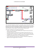
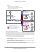
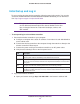
Figure 10. Example: Advanced network with VLANs and SSIDs
The access points and wireless controller are connected in the same subnet and same VLAN
and use the same IP address range that is assigned for that subnet. There are no routers
between the access points and the wireless controller. The access points are connected to a
PoE switch, which, in turn, is connected to the wireless controller. The uplink of the PoE
switch connects to a Layer 3 switch or router that provides Internet access.
This network configuration has the following prerequisites:
• VLANs 10, 20, and 100 are tagged VLANs and are configured on both the wireless
controller and the PoE switch.
• The wireless controller is connected to the PoE switch through default VLAN 1. You
manage the wireless controller from a computer over VLAN 1 through the PoE switch.
• The DHCP server on the wireless controller is configured in management VLAN 100 to
enable the access points to receive an IP address through VLAN 100.
• The PoE switch port to which the wireless controller is connected is configured as a
tagged port to allow tagged traffic from VLAN 100.