
Quick Reference Guide

Introduction
14
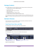
ProSAFE Wireless Controller WC9500
From left to right, the wireless controller’s back panel components are:
• Power supply. 100–240V, 5A, 47–63 Hz power supply, which includes the following
external components:
- AC power socket. Attach the power cord to this socket. (There is no separate on/off
power switch.)
- Handle
. The handle allows for easy removal and insertion.
- LED. The LED is lit green when the power supply functions correctly
. If the LED is off,
power is not supplied to the power supply, or there is a problem.
• Fans
. Two double fans, each of which can be easily exchanged.
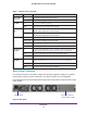
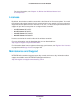
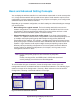
Bottom Panel with Product Label
The product label on the bottom of the wireless controller’s enclosure displays the default IP
address, default user name, and default password, as well as regulatory compliance, input
power, and other information.
Figure 4. Product label
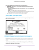
WC9500 Wireless Controller System Components
A WC9500 wireless controller system consists of one or more wireless controllers and a
collection of access points that are organized into groups based on location or network
access.
The wireless controller system can include a single wireless controller, a single wireless
controller with a backup wireless controller for N:1 redundancy, or a group of up to three
stacked wireless controllers, with or without a redundant wireless controller. Redundancy and
stacking will be supported in a future release.