
Quick Reference Guide


Introduction
13
ProSAFE Wireless Controller WC9500
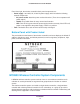
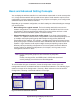
Back Panel Features
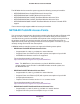
The wireless controller comes with a single internal power supply but supports an optional
second power supply for power redundancy. The power supplies are hot-swappable.
The following figure shows the back panel components of the wireless controller with a single
power supply.
Power supply
Slot for an optional
second power supply
Figure 3. Back panel
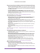
Status LED
(continued)
Off The wireless controller does not have power.
Blinking yellow Firmware is being upgraded.
Fan LED Green The fans are functioning correctly.
Yellow One or more fans are not functioning correctly.
Stack Master
LED
Green The wireless controller functions as the primary controller (master) in a stack.
(Stacking will be supported in a future release.)
Yellow The wireless controller functions as a secondary controller (slave) in a stack.
(Stacking will be supported in a future release.)
SFP slot LEDs Green The slot is operating at 10G.
Blinking green Data is being transmitted or received at 10G.
Yellow The slot is operating at 1G.
Blinking yellow Data is being transmitted or received at 1G.
Left Ethernet
port LED
Off The port has no physical link, that is, no Ethernet cable is plugged into the
wireless controller (see Ethernet Port LEDs Are Not Lit on page 199).
Green The port has detected a link with a connected Ethernet device.
Blinking green Data is being transmitted or received by the port.
Right Ethernet
port LED
Off The port has no physical link, that is, no Ethernet cable is plugged into the
wireless controller (see Ethernet Port LEDs Are Not Lit on page 199).
Green The port is operating at 1000 Mbps.
Yellow The port is operating at 100 Mbps or 10 Mbps.
Table 1. LED functions (continued)
LED Status Description