
Quick Reference Guide


14 | Chapter 1. Introduction
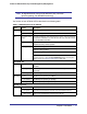
ProSecure Web/Email Security Threat Management (STM) Appliance
• ProSecure™ Web/Email Security Threat Management Applliance STM150, STM300, or
STM600 Installation Guide
• Depending on the model purchased, service registration card with one or more license
keys
If any of the parts are incorrect, missing, or damaged, contact your NETGEAR dealer. Keep
the carton, including the original packing materials, in case you need to return the product for
repair.
Hardware Features
The front panel ports and LEDs, rear panel ports, and bottom label of the STM models are
described in this section.
Front Panel Ports and LEDs
The front panels of the three STM models provide different components.
STM150 Front Panel
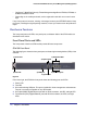
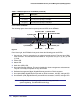
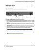
The following figure shows the front panel ports and status light-emitting diodes (LEDs) of the
STM150:
Figure 2.
From left to right, the STM150’s front panel shows the following ports and LEDs:
1. Power LED.
2. Test LED.
3. One nonfunctioning USB port. This port is included for future management enhancements.
The port is currently not operable on any STM model.
4. One uplink (WAN) Gigabit Ethernet port with an RJ-45 connector, left LED, and right LED.
5. Four downlink (LAN) Gigabit Ethernet ports with RJ-45 connectors, left LEDs, and right
LEDs.
1) Power LED
2) Test LED
3) USB port
4) Uplink port
5) Downlink ports
4) Uplink LEDs
5) Downlink LEDs