
Quick Reference Guide


ProSafe Wireless-N VPN Firewall SRXN3205 Reference Manual
VPN Firewall and Network Management 9-13
v1.0, January 2010
2. Configure the following fields in the Create New SNMP Configuration Entry section:
• Enter the IP address of the SNMP manager in the IP Address field and the subnet mask in
the Subnet Mask field.
– If you want to allow only the host address to access the VPN firewall and receive
traps, enter an IP Address of, for example, 192.168.1.101 with a subnet mask of
255.255.255.255.
– If you want to allow a subnet access to the VPN firewall through SNMP, enter an IP
address of, for example, 192.168.1.101 with a subnet mask of 255.255.255.0. The
traps will still be received on 192.168.1.101, but the entire subnet will have access
through the community string.
– If you want to make the VPN firewall globally accessible using the community string,
but still receive traps on the host, enter 0.0.0.0 as the subnet mask and an IP address
for where the traps will be received.
• Enter the trap port number of the configuration in the Port field. The default is 162.
• Enter the trap community string of the configuration in the Community field.
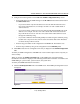
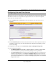
3. Click add to create the new configuration. The entry is displayed in the SNMP Configuration
table.
To modify an SNMP configuration, click edit in the Action column adjacent to the entry that you
wish to modify.
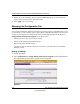
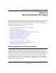
When you click on the SNMP System Info link on the SNMP screen, the VPN firewall’s
identification information is displayed. This following identification information is available to the
SNMP Manager: system contact, system location, and system name.
To modify the SNMP identification information:
1. Click the SNMP System Info link on the SNMP screen. The SNMP SysConfiguration screen
is displayed.
Figure 9-5