
User Manual
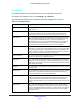
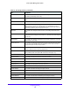
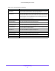
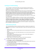
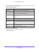
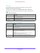
Table Of Contents
- S3300 Smart Managed Pro Switch
- Contents
- 1. Getting Started
- Getting Started with the NETGEAR Switch
- Switch Management Interface
- Connect the Switch to the Network
- Discover a Switch in a Network with a DHCP Server
- Discover a Switch in a Network without a DHCP Server
- Configure the Network Settings on the Administrative System
- Access the Management Interface from a Web Browser
- Understand the User Interfaces
- Interface Naming Convention
- Configuring Interface Settings
- Online Help
- Registration
- 2. Configure System Information
- 3. Configuring Switching
- 4. Configuring Routing
- 5. Configuring Quality of Service
- 6. Managing Device Security
- 7. Maintenance
- 8. Monitoring the System
- A. Configuration Examples
- B. Hardware Specifications and Default Values

Configuring Routing
215
S3300 Smart Managed Pro Switch
6. Click the box under each port or LAG to add to the VLAN as a VLAN member.
Each port or LAG has three modes:
• T
(Tagged). Select the ports on which all frames transmitted for this VLAN will be
tagged. The ports that are selected will be included in the VLAN.
• U(Unt
agged). Select the ports on which all frames transmitted for this VLAN will be
untagged. The ports that are selected will be included in the VLAN.
• BLANK(Autodetect). Select the
ports that can be dynamically registered in this
VLAN via GVRP. This selection has the effect of excluding a port from the selected
VLAN.
7. Click the Ap
ply button.
VLAN Routing Configuration
Use the VLAN Routing Configuration screen to view information about the VLAN routing
interfaces configured on the system or to assign an IP address and subnet mask to VLANs
on the system.
To configure VLAN routing:
1. Select Rou
ting > VLAN > VLAN Routing.
2. From the VL
AN list, select the VLAN you want to configure for VLAN routing.
This field will display the all IDs of VLANs configured on this switch.
3. Ente
r an IP address of the VLAN routing interface.
4. Ente
r a subnet mask for the VLAN routing interface.
5. In the IP
MTU field, specify the maximum size of IP packets sent on an interface.
A valid range is from 68 bytes to the link MT
U. The default value is 1500. A value of 0
indicates that the IP MTU is unconfigured. When the IP MTU is unconfigured, the router
uses the link MTU as the IP MTU. The link MTU is the maximum frame size minus the
length of the layer 2 header.
6. Click the Ad
d button.
The following table describes the VLAN routing interface status information available on the
scre
en.
Table 80. VLAN routing interface information
Field Description
Port The port number assigned to the VLAN Routing Interface.
MAC Address The MAC Address assigned to the VLAN Routing Interface.