
User's Manual


Table Of Contents
- ProSecure Web/Email Security Threat Management (STM) Appliance Reference Manual
- Contents
- About This Manual
- Chapter 1 Introduction
- Chapter 2 Using the Setup Wizard to Provision the STM in Your Network
- Choosing a Deployment Scenario
- Understanding the Steps for Initial Connection
- Logging In to the STM
- Using the Setup Wizard to Perform the Initial Configuration
- Setup Wizard Step 1 of 10: Introduction
- Setup Wizard Step 2 of 11: Networking Settings
- Setup Wizard Step 3 of 11: Time Zone
- Setup Wizard Step 4 of 11: Email Security
- Setup Wizard Step 5 of 11: Web Security
- Setup Wizard Step 6 of 11: Email Notification Server Settings
- Setup Wizard Step 7 of 11: Update Settings
- Setup Wizard Step 8 of 11: HTTP Proxy Settings
- Setup Wizard Step 9 of 11: Web Categories
- Setup Wizard Step 10 of 11: Configuration Summary
- Setup Wizard Step 11 of 11: Restarting the System
- Verifying Proper Installation
- Registering the STM with NETGEAR
- What to Do Next
- Chapter 3 Performing Network and System Management
- Configuring Network Settings
- Configuring Session Limits and Timeouts
- Configuring the HTTP Proxy Settings
- About Users with Administrative and Guest Privileges
- Configuring Remote Management Access
- Using an SNMP Manager
- Managing the Configuration File
- Updating the Software
- Configuring Date and Time Service
- Managing Digital Certificates
- Managing the Quarantine Settings
- Performance Management
- Chapter 4 Content Filtering and Optimizing Scans
- About Content Filtering and Scans
- Configuring E-mail Protection
- Configuring Web and Services Protection
- Configuring Application Control
- Setting Scanning Exclusions and Web Access Exceptions
- Chapter 5 Managing Users, Groups, and Authentication
- About Users, Groups, and Domains
- Configuring Groups
- Configuring User Accounts
- Configuring Authentication
- Global User Settings
- Viewing and Logging Out Active Users
- Chapter 6 Monitoring System Access and Performance
- Chapter 7 Troubleshooting and Using Online Support
- Appendix A Default Settings and Technical Specifications
- Appendix B Related Documents
- Index
ProSecure Web/Email Security Threat Management (STM) Appliance Reference Manual
1-12 Introduction
v1.0, September 2009
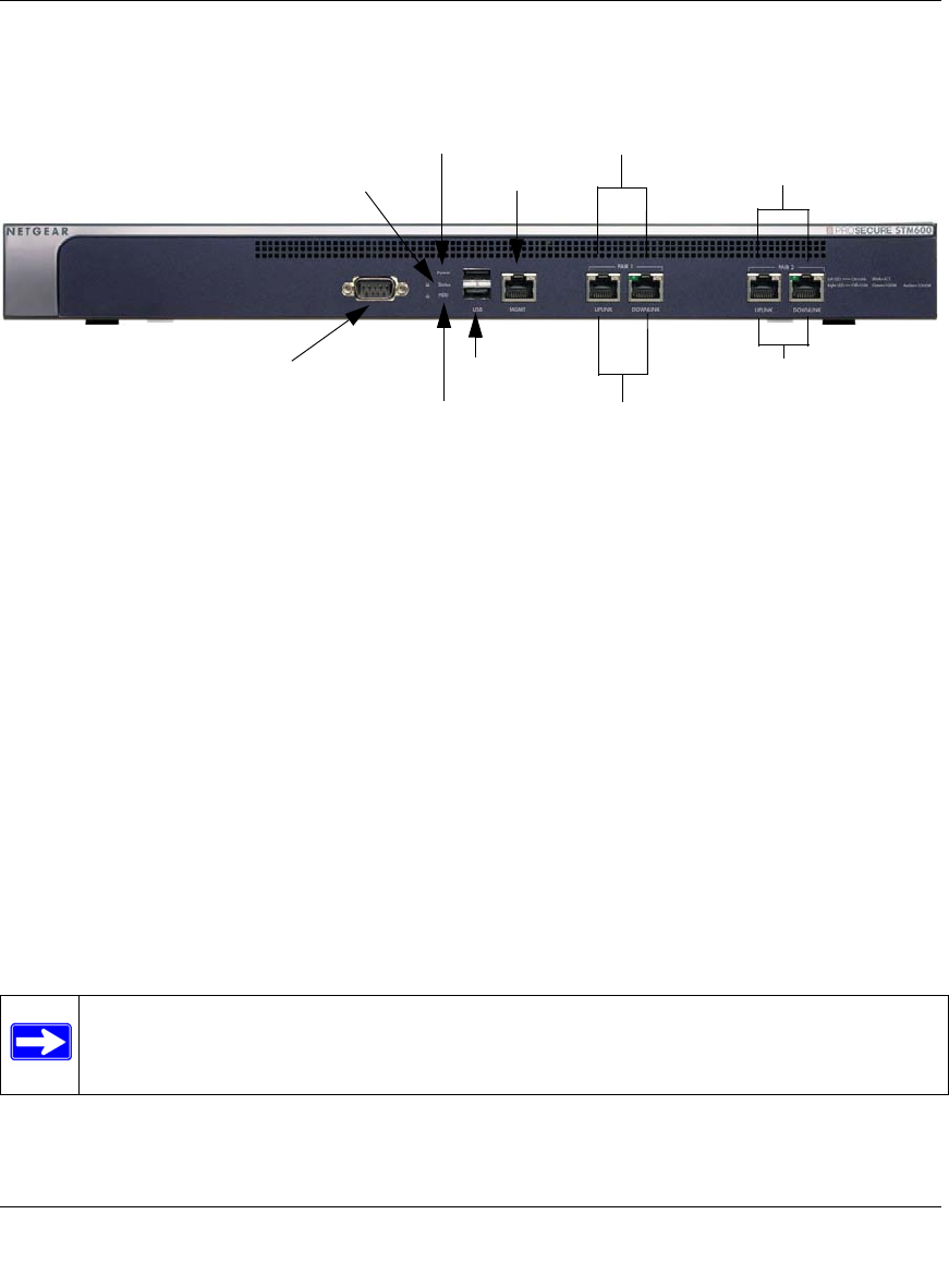
Front Panel STM600
Figure 1-4 shows the front panel ports and LEDs of the STM600.
From left to right, the STM600’s front panel shows the following ports and LEDs:
1. Console port. Port for connecting to an optional console terminal. The ports has a DB9 male
connector. The default baud rate is 9600 K. The pinouts are: (2) Tx, (3) Rx, (5) and (7) Gnd.
2. Power LED.
3. Status LED.
4. Hard drive (HDD) LED.
5. One non-functioning USB port: this port is included for future management enhancements.
The port is currently not operable on any STM model.
6. Dedicated management (Mgmt) Gigabit Ethernet port with an RJ-45 connector.
7. Pair 1 uplink (WAN) and downlink (LAN) Gigabit Ethernet ports with RJ-45 connectors, left
LEDs, and right LEDs.
8. Pair 2 uplink (WAN) and downlink (LAN) Gigabit Ethernet ports with RJ-45 connectors, left
LEDs, and right LEDs.
Figure 1-4
Note: All Gigabit Ethernet ports provide switched N-way, automatic speed-negotiating,
auto MDI/MDIX technology.
3) Status LED
4) HDD LED
5) USB Port
2) Power LED
1) Console Port
6) Mgmt Port
7) Pair 1 LEDs
8) Pair 2 LEDs
7) Pair 1 Ports
8) Pair 2 Ports