
User's Manual


Table Of Contents
- ProSecure Web/Email Security Threat Management (STM) Appliance Reference Manual
- Contents
- About This Manual
- Chapter 1 Introduction
- Chapter 2 Using the Setup Wizard to Provision the STM in Your Network
- Choosing a Deployment Scenario
- Understanding the Steps for Initial Connection
- Logging In to the STM
- Using the Setup Wizard to Perform the Initial Configuration
- Setup Wizard Step 1 of 10: Introduction
- Setup Wizard Step 2 of 11: Networking Settings
- Setup Wizard Step 3 of 11: Time Zone
- Setup Wizard Step 4 of 11: Email Security
- Setup Wizard Step 5 of 11: Web Security
- Setup Wizard Step 6 of 11: Email Notification Server Settings
- Setup Wizard Step 7 of 11: Update Settings
- Setup Wizard Step 8 of 11: HTTP Proxy Settings
- Setup Wizard Step 9 of 11: Web Categories
- Setup Wizard Step 10 of 11: Configuration Summary
- Setup Wizard Step 11 of 11: Restarting the System
- Verifying Proper Installation
- Registering the STM with NETGEAR
- What to Do Next
- Chapter 3 Performing Network and System Management
- Configuring Network Settings
- Configuring Session Limits and Timeouts
- Configuring the HTTP Proxy Settings
- About Users with Administrative and Guest Privileges
- Configuring Remote Management Access
- Using an SNMP Manager
- Managing the Configuration File
- Updating the Software
- Configuring Date and Time Service
- Managing Digital Certificates
- Managing the Quarantine Settings
- Performance Management
- Chapter 4 Content Filtering and Optimizing Scans
- About Content Filtering and Scans
- Configuring E-mail Protection
- Configuring Web and Services Protection
- Configuring Application Control
- Setting Scanning Exclusions and Web Access Exceptions
- Chapter 5 Managing Users, Groups, and Authentication
- About Users, Groups, and Domains
- Configuring Groups
- Configuring User Accounts
- Configuring Authentication
- Global User Settings
- Viewing and Logging Out Active Users
- Chapter 6 Monitoring System Access and Performance
- Chapter 7 Troubleshooting and Using Online Support
- Appendix A Default Settings and Technical Specifications
- Appendix B Related Documents
- Index
ProSecure Web/Email Security Threat Management (STM) Appliance Reference Manual
1-10 Introduction
v1.0, September 2009
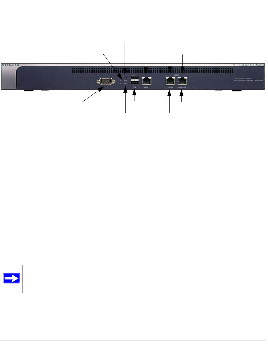
Front Panel STM300
Figure 1-3 shows the front panel ports and LEDs of the STM300.
From left to right, the STM300’s front panel shows the following ports and LEDs:
1. Console port. Port for connecting to an optional console terminal. The ports has a DB9 male
connector. The default baud rate is 9600 K. The pinouts are: (2) Tx, (3) Rx, (5) and (7) Gnd.
2. Power LED.
3. Status LED.
4. Hard drive (HDD) LED.
5. One non-functioning USB port: this port is included for future management enhancements.
The port is currently not operable on any STM model.
6. Dedicated management (Mgmt) Gigabit Ethernet port with an RJ-45 connector.
7. One uplink (WAN) Gigabit Ethernet port with an RJ-45 connector, left LED, and right LED.
8. One downlink (LAN) Gigabit Ethernet port with RJ-45 connectors, left LEDs, and right LED.
Figure 1-3
Note: All Gigabit Ethernet ports provide switched N-way, automatic speed-negotiating,
auto MDI/MDIX technology.
3) Status LED
4) HDD LED
5) USB Port
7) Uplink Port
8) Downlink Port
7) Uplink LEDs
8) Downlink LEDs
2) Power LED
1) Console Port
6) Mgmt Port