Smart Switch Series Software Manual NETGEAR, Inc.
© 2005 by NETGEAR, Inc. All rights reserved. Trademarks NETGEAR, Inc. NETGEAR, the Netgear logo, The Gear Guy and Everybody’s connecting are trademarks of Netgear, Inc. in the United States and/or other countries. Other brand and product names are trademarks of their respective holders. Information is subject to change without notice. All rights reserved.
Contents Chapter 1 About This Guide Audience .........................................................................................................................1-1 Why the Document was Created ....................................................................................1-1 How to Use This Document ............................................................................................1-1 Typographical Conventions .............................................................................
Switch> VLAN> IEEE802.1Q Tag VLAN ..........................................................3-7 Switch> Trunking Page ...........................................................................................3-9 Switch> Monitor Page ...........................................................................................3-10 Switch> Advanced> Jumbo Frame ..................................................................3-10 Switch> Advanced> Spanning Tree Page ............................................
Chapter 1 About This Guide Thank you for purchasing the NETGEAR™ Smart Switch Series Switch. Audience This reference manual assumes that the reader has basic-to-intermediate computer and Internet skills. However, basic computer network, Internet, and wireless technology tutorial information is provided in the Appendices. This document describes configuration commands for the Smart Switch Series Switch software. The commands can be accessed from the CLI, telnet, and Web interfaces.
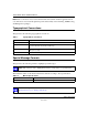
Smart Switch Series Software Manual Note: Refer to the release notes for the Smart Switch Series Switch Software application level code. The release notes detail the platform specific functionality of the Switching, SNMP, Config, and Management packages. Typographical Conventions This guide uses the following typographical conventions: Table 1. Typographical conventions italics Emphasis. bold times roman User input. [Enter] Named keys in text are shown enclosed in square brackets.
Chapter 2 Switch Management Overview This chapter gives an overview of switch management, including the methods you can use to manage your NETGEAR Smart Switch Series Switch. Topics include: • Management Access Overview • SNMP Access • Protocols Management Access Overview Your NETGEAR Smart Switch contains software for viewing, changing, and monitoring the way it works. This management software is not required for the switch to work.
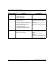
Smart Switch Series Software Manual Table 2-1.
Smart Switch Series Software Manual Switch Management Overview 2-3 July 2005
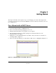
Chapter 3 Getting Started This chapter will walk you through the steps to start managing your switch. This chapter will cover how to get started in a network with a DHCP server (most common) as well as if you do not have a DHCP server. For a Network with a DHCP Server 1. 2. 3. 4. 5. 6. Connect the Smart Switch to a DHCP network. Power on the Smart Switch by plugging in power cord. Install the Smartwizard Discovery program on your computer Start the Smartwizard Discovery utility.
Smart Switch Series Software Manual Figure 3-2: Smartwizard Discovery > Web Access 7. To manage your switch via your web browser, click Web Access. The main page below will display. The default password is password.
Smart Switch Series Software Manual For a Network without a DHCP Server 1. Connect your switch to your existing network. 2. Power on your switch by plugging in the power cord. 3. The default IP is 192.168.0.239. 4. Install the Smartwizard Discovery program on your PC. 5. Start the Smartwizard Discovery utility. 6. Click Discover to find your switch. 7. Click Configuration Setting. Figure 3-4: Assigning the switch a static IP address 8. Choose Disable on DHCP. 9.
Smart Switch Series Software Manual 11. To manage your switch via your web browser, click Web Access. The main page below will display. The default password is password.
Smart Switch Series Software Manual 3-5 Getting Started July 2005
Chapter 4 Web-Based Management Interface Your NETGEAR Smart Switch series provides a built-in browser interface that lets you configure and manage it remotely using a standard Web browser such as Microsoft Internet Explorer or Netscape Navigator. This interface also allows for system monitoring of the switch. The help page will cover many of the basic functions and features of the switch and its web interface. Web Management requires either Microsoft Internet Explorer 5.0 or later or Netscape Navigator 6.
Smart Switch Series Software Manual There is a Help Menu in the top of right side of screen. Click the help to read the full Help Menu. On some pages, there is a Help button. If you click that button, you will go to the part of the Help Menu that discusses that page. Within the various browser interface pages, there are several buttons that you can use. Their names and functions are below: Browse: Locates a certain path for a desired file.
Smart Switch Series Software Manual • Flow Control: Indicates whether Flow Control support is set for on (Enabled) or off (Disabled). The default setting for all ports is enabled. • Link Status: Indicates the current speed and duplex for the port. DOWN means no link. The next part of the Switch Status page shows the Virtual Local Area Network (VLAN) status. A VLAN is a way to electronically separate specified ports on the same switch into separate broadcast domains.
Smart Switch Series Software Manual • The DHCP function is enabled by default. Click Static IP Address to disable the DHCP function. • Enter site-specific IP address, Subnet mask and Gateway in the appropriate boxes • Click Apply to activate the setting System> Password Page The password entered is encrypted on the screen and will display as a sequence of asterisks (*). The default password is ‘password’ and can be changed here.
Smart Switch Series Software Manual • Flow Control: Indicates whether Flow Control support is set for on (Enabled) or off (Disabled). The default setting for all ports is enabled. • Link Status: Indicates the current speed and duplex for the port. DOWN means no link. Switch> Port Configuration: Set speed • Click a port ID. • Click to select a speed from the pull-down menu under Speed. • Click Apply to activate the new speed. Note: Please be aware that speed must set as same as link partner.
Smart Switch Series Software Manual • Tx Error: Transmitted packet/s with error. • Rx Error: Received packet/s with error. Packets are counted as TX Error if they: • Had a late collision detected during the transmission (512 bit-times into the transmission). • Experienced 16 failed transmission attempts due to collision. • Were dropped due to lack of resources. Packets are counted as RX Error if they: • Were less than 64 bytes or greater than 1522 bytes? • Had a bad FCS.
Smart Switch Series Software Manual • IEEE 802.1Q VLAN (Tagged VLAN) • Port-based VLAN • ID: The port number on the switch • Description: User-definable • Member: Indicates which port/s belong to a VLAN group Switch> VLAN> Port-based VLAN Multiple port-based VLAN groups are supported on the switch, and any one port can belong to different VLAN groups. The number of supported port-based VLAN groups varies according to the switch model.
Smart Switch Series Software Manual Switch> VLAN> IEEE802.1Q Tag VLAN Depending on your model switch there are up to 64 static Tag VLAN groups supported on your switch. The VLAN tagging option is a standard set by the IEEE to facilitate the spanning of VLANs across multiple switches (Reference: Appendix A and IEEE Std 802.1Q-1998 Virtual Bridged Local Area Networks). Click to select IEEE802.1Q VLAN. A screen pops up to confirm this change. All ports are set belonging to VLAN 1 by default, all untagged.
Smart Switch Series Software Manual Note: To allow untagged packets to participate in VLAN 2, make sure to change the Port VLAN Ids (PVID) for the relevant ports. Access the PVID Settings by using the VLAN ID drop down menu. Delete a VLAN Group • Under the VLAN ID drop down menu, select the VLAN you want to remove. • Click to select Remove VLAN. • Click Apply. PVID Setting All untagged packets entering the switch will by default be tagged with the port’s Primary VLAN Identification (PVID).
Smart Switch Series Software Manual Switch> Trunking Page Port Trunking is a feature that allows multiple links between switches to work as one virtual link (aggregate link). Trunks can be defined for similar port types only. For example, a 10/100 port cannot form a Port Trunk with a gigabit port. For 10/100 ports, trunks can only be formed within the same bank. A bank is a set of eight ports, such as ports 1 to 8, ports 9 to 16, ports 17 to 24, or port 25 and port 26, on the same switch unit.
Smart Switch Series Software Manual Switch> Monitor Page The Monitor feature allows you to configure any port's incoming and/or outgoing traffic to be mirrored to a pre-defined sniffer port. Sniffer Mode: • .Disable - disable port mirroring globally. • .RX - mirroring only the ingress traffic to the designated source ports. • .TX - mirroring only the egress traffic to the designated source ports. • Both - mirroring both incoming and outgoing traffic on the designated source ports.
Smart Switch Series Software Manual Switch> Advanced> Spanning Tree Page • Fast Link: When a port running the standard Spanning Tree Protocol (STP) is connected, it will go through the STP negotiation ( listening -> learning -> forwarding or blocking ) before it will be fully available. If a server is trying to access a client through the switch running the STP negotiation, it will not be able to connect to it immediately. This can be a problem for some networks.
Smart Switch Series Software Manual Firmware Menu There are 2 options available: • Configuration Backup • Factory Reset Firmware> Configuration Backup Page You can backup the system and switch settings to your workstation. This can help you to reconfigure the switch quickly if you have to re-set to factory defaults. Additionally, if you want to try out different configurations on the switch, this feature will enable you to quickly return to a previous configuration.
Smart Switch Series Software Manual Note: Please be aware that the switch will reboot after a successful reset. Logout When finished with all configuration and settings, click Logout to disconnect the current browser connection. The login page will pop up.
Chapter 5 Software Upgrade The application software for the Smart Switch is upgradeable, enabling your switch to take advantage of improvements and additional features as they become available. The upgrade procedure and the required equipment are described in the following section. The upgrade procedure is as follows: 1. Save the new firmware to your computer. 2. Start the Smartwizard Discovery utility program. 3. Select your switch by clicking on it. 4. Then click Firmware Upgrade. 5.
Smart Switch Series Software Manual 5-2 Software Upgrade July 2005
Appendix B IEEE 802.1Q Virtual Local Area Network (VLAN) A Local Area Network (LAN) can generally be defined as a broadcast domain. Hubs, bridges or switches in the same physical segment or segments connect all end node devices. End nodes can communicate with each other without the need for a router. Routers connect LANs together, routing the traffic to appropriate port.
Smart Switch Series Software Manual IEEE 802.1Q VLANs Packets received by the switch will be treated in the following way: • When an untagged packet enters a port, it will be automatically tagged with the port’s default VLAN ID tag number. Each port has a default VLAN ID setting that is user configurable (the default setting is 1). The default VLAN ID setting for each port can be changed in PVID Setting page.
Smart Switch Series Software Manual 4. • Default VLAN: Port 7 – Port 26 (all U), VID = 1 • VLAN 1: Port 1 (U), Port 2 (U), Port 3 (T), VID = 10 • VLAN 2: Port 4 (U), Port 5 (T), Port 6 (U), VID = 20. The following scenarios will produce results as described below: (1). If an untagged packet enters Port 1, the switch will tag it with a VLAN tag value 10. The packet will have access to Port 2 and Port 3. The outgoing packet will be stripped away its tag becoming an untagged packet as it leaves Port 2.
Smart Switch Series Software Manual B-4 IEEE 802.
Appendix C Port-Based VLAN Port-based VLAN will help efficiently confine the broadcast traffic to the switch ports. This switch allows up to 26 port-based VLAN groups, any one port can belong to different VLAN groups. The default VLAN group port-based VLAN that have all ports belonging to VLAN 1. Port-based VLANs Packets received by the switch will be treated in the following way: • When a packet enters a port, it only can proceed to the VLAN which the port belongs to.
Smart Switch Series Software Manual • Setting up first VLAN group (IT), VLAN ID = 01, with membership of all ports. Since VLAN ID 01 has been setup by default, you will have to remove the ports that belong to all other VLAN group except port 25. • Ports 7 and 8 are kept for the usage of connecting file server and printer server. Sales and Marketing departments can share file archives and printing services. • Port 25 provides Gigabit speed for email server and Internet connection.
Appendix D Cabling Guidelines This appendix provides specifications for cables used with a NETGEAR Smart Switch Series Switch. Fast Ethernet Cable Guidelines Fast Ethernet uses UTP cable, as specified in the IEEE 802.3u standard for 100BASE-TX.The specification requires Category 5 UTP cable consisting of either two-pair or four-pair twisted insulated copper conductors bound in a single plastic sheath. Category 5 cable is certified up to 100 MHz bandwidth.
Smart Switch Series Software Manual Category 5 Cable Category 5 distributed cable that meets ANSI/EIA/TIA-568-A building wiring standards can be a maximum of 328 feet (ft.) or 100 meters (m) in length, divided as follows: 20 ft. (6 m) between the hub and the patch panel (if used) 295 ft. (90 m) from the wiring closet to the wall outlet 10 ft. (3 m) from the wall outlet to the desktop device The patch panel and other connecting hardware must meet the requirements for 100 Mbps operation (Category 5). Only 0.
Smart Switch Series Software Manual Table-D-1. Electrical Requirements of Category 5 Cable SPECIFICATIONS CATEGORY 5 CABLE REQUIREMENTS Number of pairs Four Impedance 100 ± 15% Mutual capacitance at 1 KHz 5.6 nF per 100 m Maximum attenuation (dB per 100 m, at 20° C) at 4 MHz: 8.2 at 31 MHz: 11.7 at 100 MHz: 22.
Smart Switch Series Software Manual Figure D-2 illustrates crossover twisted pair cable. Figure D-2: Crossover Twisted-Pair Cable Patch Panels and Cables If you are using patch panels, make sure that they meet the 100BASE-TX requirements. Use Category 5 UTP cable for all patch cables and work area cables to ensure that your UTP patch cable rating meets or exceeds the distribution cable rating. To wire patch panels, you need two Category 5 UTP cables with an RJ-45 plug at each end, as shown here.
Smart Switch Series Software Manual Note: Flat “silver satin” telephone cable may have the same RJ-45 plug. However, using telephone cable results in excessive collisions, causing the attached port to be partitioned or disconnected from the network. Using 1000BASE-T Gigabit Ethernet over Category 5 Cable When using the new 1000BASE-T standard, the limitations of cable installations and the steps necessary to ensure optimum performance must be considered.
Smart Switch Series Software Manual Unlike 10BASE-T and 100BASE-TX, which use only two of the four pairs of wires within the Category 5, 1000BASE-T uses all four pairs of the twisted pair. Make sure all wires are tested ⎯ this is important. Factors that affect the return loss are: The number of transition points, as there is a connection via an RJ-45 to another connector, a patch panel, or device at each transition point. Removing the jacket that surrounds the four pairs of twisted cable.
Smart Switch Series Software Manual Figure D-4 shows the RJ-45 plug and RJ-45 connector. Figure D-4: RJ-45 Plug and RJ-45 Connector with Built-in LEDs Table D-2 lists the pin assignments for the 10/100 Mbps RJ-45 plug and the RJ-45 connector. Table-D-2.
Smart Switch Series Software Manual Table-D-3. 100/1000 Mbps RJ-45 Plug and RJ-45 Connector Pin Assignments PIN CHANNEL DESCRIPTION 1 2 A Rx/Tx Data + Rx/Tx Data 3 6 B Rx/Tx Data + Rx/Tx Data 4 5 C Rx/Tx Data + Rx/Tx Data 7 8 D Rx/Tx Data + Rx/Tx Data Conclusion For optimum performance of your 1000BASE-T product, it is important to fully qualify your cable installation and ensure it meets or exceeds ANSI/EIA/TIA-568-A:1995 or ISO/IEC 11801:1995 Category 5 specifications.
Appendix A Default Settings This appendix provides default settings for the NETGEAR Smart Switches. You can always configure the switch to default settings by using the Factory Reset function from a Web browser. Table A-1.
Smart Switch Series Software Manual A-2 Default Settings July 2005
Index Numerics 802.
CLI Configure System Restore 5-30 CLI Configure System Save 5-30 CLI Configure System Stat-Reset 5-34 CLI Configure System Username 5-31 CLI Configure System Web 5-30 CLI Configure Trap 5-25 CLI Exit 5-3 CLI Help 5-2 CLI Manual Syntax 5-1 D Device Reset 4-18 Differentiated Service 3-20 Differentiated Service Code Points 3-20 DiffServ 3-20 Direct Console Access 3-1 Disable Advanced Alerting 4-20, 4-22 Documentation updates 1-2 DSCP 3-20 CLI Ping 5-2 CLI Show 5-3 CLI Show DiffServ 5-4 CLI Show Interfaces 5-
Inbound Errors 4-6 Outbound Error Rate 4-6 Inbound Non-unicast Packet rate 4-5 Outbound Errors 4-6 Inbound Non-unicast Packets 4-6 Outbound Non-unicast Packet Rate 4-6 Inbound Octet Rate 4-5 Outbound Non-unicast Packets 4-6 Inbound Octets 4-6 Outbound Octet Rate 4-5 Inbound Unicast Packet Rate 4-5 Outbound Octets 4-6 Inbound Unicast Packets 4-6 Outbound Unicast Packet Rate 4-5 IP Configuration 3-8, 4-13 Outbound Unicast Packets 4-6 L P Last Saved option 3-19, 4-29 Passwords 4-18 Port Conf
SNMP> Host Table 4-41 Why the Document was Created 1-1 SNMP> Trap Setting 4-42 SNMP> Trap Settings 3-30 Z Spanning Tree 3-23 ZTerm 3-2 Spanning Tree > Port Setting 4-36 Spanning Tree >Bridge Settings 4-35 Spanning Tree Protocol 4-21 Spanning Tree> Bridge Settings 3-23 State field 3-9 Static Addresses 3-26 Static Multicast Administration 3-27 Static Multicast Membership 3-28 Statistics 3-5, 4-8 Statistics Rest 3-6 STP 4-21 Support for Standard MIBs 3-29, 4-40 Switch Statistics 4-5 System Configuration