ProSafe Managed Switch Command Line Interface (CLI) User Manual 10.0 GSM7328Sv2 GSM7352Sv2 GSM7228PS GSM7252PS M5300-28G3 M5300-52G3 M5300-28G-POE+ M5300-52G-POE+ M5300-28GF3 M5300-28G M5300-52G 350 East Plumeria Drive San Jose, CA 95134 USA November 2012 202-11054-02 1.
ProSafe Managed Switch © 2012 NETGEAR, Inc. All rights reserved. No part of this publication may be reproduced, transmitted, transcribed, stored in a retrieval system, or translated into any language in any form or by any means without the written permission of NETGEAR, Inc. Technical Support Thank you for choosing NETGEAR. To register your product, get the latest product updates, or get support online, visit us at http://support.netgear.com.
Contents Chapter 1 Using the Command-Line Interface Licensing and Command Support . . . . . . . . . . . . . . . . . . . . . . . . . . . . . . . . 8 Command Syntax . . . . . . . . . . . . . . . . . . . . . . . . . . . . . . . . . . . . . . . . . . . . 10 Command Conventions . . . . . . . . . . . . . . . . . . . . . . . . . . . . . . . . . . . . . . . 11 Common Parameter Values . . . . . . . . . . . . . . . . . . . . . . . . . . . . . . . . . . . . 11 Unit/Slot/Port Naming Convention . . . . . . . . . . . .
ProSafe Managed Switch Port-Channel/LAG (802.3ad) Commands . . . . . . . . . . . . . . . . . . . . . . . . 123 Port Mirroring . . . . . . . . . . . . . . . . . . . . . . . . . . . . . . . . . . . . . . . . . . . . . . 139 Static MAC Filtering . . . . . . . . . . . . . . . . . . . . . . . . . . . . . . . . . . . . . . . . . 141 DHCP L2 Relay Agent Commands . . . . . . . . . . . . . . . . . . . . . . . . . . . . . 145 DHCP Client Commands . . . . . . . . . . . . . . . . . . . . . . . . . . . . . . . . . . .
ProSafe Managed Switch Chapter 6 IP Multicast Commands Multicast Commands . . . . . . . . . . . . . . . . . . . . . . . . . . . . . . . . . . . . . . . .339 DVMRP Commands . . . . . . . . . . . . . . . . . . . . . . . . . . . . . . . . . . . . . . . . .344 PIM Commands . . . . . . . . . . . . . . . . . . . . . . . . . . . . . . . . . . . . . . . . . . . . 349 Internet Group Message Protocol (IGMP) Commands. . . . . . . . . . . . . . .360 IGMP Proxy Commands. . . . . . . . . . . . . . . . . . . . . . . .
ProSafe Managed Switch System Utility and Clear Commands . . . . . . . . . . . . . . . . . . . . . . . . . . . . 562 Simple Network Time Protocol (SNTP) Commands. . . . . . . . . . . . . . . . . 572 DHCP Server Commands . . . . . . . . . . . . . . . . . . . . . . . . . . . . . . . . . . . . 579 DNS Client Commands . . . . . . . . . . . . . . . . . . . . . . . . . . . . . . . . . . . . . . 591 Packet Capture Commands . . . . . . . . . . . . . . . . . . . . . . . . . . . . . . . . . . .
ProSafe Managed Switch Captive Portal Configuration Commands . . . . . . . . . . . . . . . . . . . . . . . . .751 Captive Portal Status Commands . . . . . . . . . . . . . . . . . . . . . . . . . . . . . .757 Captive Portal Client Connection Commands . . . . . . . . . . . . . . . . . . . . .761 Captive Portal Interface Commands. . . . . . . . . . . . . . . . . . . . . . . . . . . . .765 Captive Portal Local User Commands . . . . . . . . . . . . . . . . . . . . . . . . . . .
1. Using the Command-Line Interface 1 The command-line interface (CLI) is a text-based way to manage and monitor the system. You can access the CLI by using a direct serial connection or by using a remote logical connection with telnet or SSH. This chapter describes the CLI syntax, conventions, and modes.
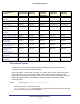
ProSafe Managed Switch Command Group or Command M5300-28G-POE+ M5300-28G M5300-52G-POE+ M5300-52G M5300-28G3 M5300-52G3 M5300-28GF3 GSM7328Sv2 GSM7352Sv2 GSM7228PS GSM7252PS Stacking Commands Supported Supported Supported Supported Supported Non-Stop Forwarding Commands Supported Supported Supported Supported Supported Stack Firmware Synchronization Commands Supported Supported Supported Supported Supported Router Discovery Protocol Commands Require license Require license Support
ProSafe Managed Switch Command Group or Command M5300-28G-POE+ M5300-28G M5300-52G-POE+ M5300-52G M5300-28G3 M5300-52G3 M5300-28GF3 GSM7328Sv2 GSM7352Sv2 GSM7228PS GSM7252PS IPv6 MLD-Proxy Commands Require license Require license Supported Supported Require license PoE Commands Supported Not Supported Not Supported Not Supported Supported MVR Commands Supported Supported Supported Not Supported Not Supported Link Local Protocol Filtering Supported Commands Supported Supported Supp
ProSafe Managed Switch • [gateway] is an optional parameter, so you are not required to enter a value in place of the parameter. The New Template User Manual lists each command by the command name and provides a brief description of the command. Each command reference also contains the following information: • Format shows the command keywords and the required and optional parameters. • Mode identifies the command mode you must be in to access the command.
ProSafe Managed Switch Name with Spaces” forces the system to accept the spaces. Empty strings (““) are not valid user-defined strings. Table 2 describes common parameter values and value formatting. Table 2. Parameter Descriptions Parameter Description ipaddr This parameter is a valid IP address. You can enter the IP address in the following formats: a (32 bits) a.b (8.24 bits) a.b.c (8.8.16 bits) a.b.c.d (8.8.8.
ProSafe Managed Switch The port identifies the specific physical port or logical interface being managed on a given slot. Table 4. Type of Ports Port Type Description Physical Ports The physical ports for each slot are numbered sequentially starting from zero. Logical Interfaces Port-channel or Link Aggregation Group (LAG) interfaces are logical interfaces that are only used for bridging functions. VLAN routing interfaces are only used for routing functions.
ProSafe Managed Switch • Quality of Service • Management (CLI, Web UI, and SNMP) • IPv6 Management—Allows management of the device through an IPv6 through an IPv6 address without requiring the IPv6 Routing package in the system. The management address can be associated with the network port (front-panel switch ports) and a routine interface (port or VLAN). • Stacking Not all modules are available for all platforms or software releases.
ProSafe Managed Switch Table 5. CLI Command Modes (Continued) Command Mode Prompt Mode Description Interface Config Switch (Interface )# Manages the operation of an interface and provides access to the router interface configuration commands. Use this mode to set up a physical port for a specific logical connection operation.
ProSafe Managed Switch Table 6 explains how to enter or exit each mode. Table 6. CLI Mode Access and Exit Command Mode Access Method Exit or Access Previous Mode User EXEC This is the first level of access. To exit, enter logout. Privileged EXEC From the User EXEC mode, enter enable. To exit to the User EXEC mode, enter exit or press Ctrl-Z. Global Config From the Privileged EXEC mode, enter configure. To exit to the Privileged EXEC mode, enter exit, or press Ctrl-Z.
ProSafe Managed Switch Table 6. CLI Mode Access and Exit (Continued) Command Mode Access Method Exit or Access Previous Mode Router RIP Config From the Global Config mode, enter router rip. To exit to the Global Config mode, enter exit. To return to the Privileged EXEC mode, enter Ctrl-Z. MAC Access-list Config From the Global Config mode, enter mac access-list extended . To exit to the Global Config mode, enter exit. To return to the Privileged EXEC mode, enter Ctrl-Z.
ProSafe Managed Switch CLI Error Messages If you enter a command and the system is unable to execute it, an error message appears. Table 7 describes the most common CLI error messages. Table 7. CLI Error Messages Message Text Description % Invalid input detected at '^' marker. Indicates that you entered an incorrect or unavailable command. The carat (^) shows where the invalid text is detected. This message also appears if any of the parameters or values are not recognized.
ProSafe Managed Switch Table 8. CLI Editing Conventions (Continued) Key Sequence Description Ctrl-Y Prints last deleted character Ctrl-Q Enables serial flow Ctrl-S Disables serial flow Ctrl-Z Return to root command prompt Tab, Command-line completion Exit Go to next lower command prompt ? List available commands, keywords, or parameters Using CLI Help Enter a question mark (?) at the command prompt to display the commands available in the current mode.
ProSafe Managed Switch You can also enter a question mark (?) after typing one or more characters of a word to list the available command or parameters that begin with the letters, as shown in the following example: (switch) #show m? mac-addr-table mac-address-table monitor Accessing the CLI You can access the CLI by using a direct console connection or by using a telnet or SSH connection from a remote management host. For the initial connection, you must use a direct connection to the console port.
2. Stacking Commands 2 This chapter contains the following sections: • Dedicated Port Stacking • Stacking Commands • Non-Stop Forwarding Commands • Stack Firmware Synchronization Commands The commands in this chapter are in two functional groups: • Show commands display switch settings, statistics, and other information. • Configuration commands configure features and options of the switch. For every configuration command, there is a show command that displays the configuration setting.
ProSafe Managed Switch supported switch types, indicating the type of the switch being preconfigured. The switch index is a 32-bit integer. This command is executed on the Primary Management Unit. Format member Mode Stack Global Config Note: Switch index can be obtained by executing the show supported switchtype command in User EXEC mode. no member This command removes a switch from the stack. The is the switch identifier of the switch to be removed from the stack.
ProSafe Managed Switch Note: If the management unit is renumbered, then the running configuration is no longer applied (that is, the stack acts as if the configuration had been cleared). Format switch renumber Mode Global Config movemanagement This command moves the Primary Management Unit functionality from one switch to another. The is the switch identifier on the current Primary Management Unit. The is the switch identifier on the new Primary Management Unit.
ProSafe Managed Switch Note: The Standby Management Unit cannot be the current Management Unit. The Standby unit should be a management-capable unit. slot This command configures a slot in the system. The is the slot identifier of the slot. The is the index into the database of the supported card types, indicating the type of the card being preconfigured in the specified slot. The card index is a 32-bit integer.
ProSafe Managed Switch to any module that is inserted into the slot. If a card is disabled, all the ports on the device are operationally disabled and shown as “unplugged” on management screens. Format set slot disable [ | all] Mode Global Config no set slot disable This command unconfigures the administrative mode of the slot(s). If you specify [all], the command removes the configuration from all slots, otherwise the configuration is removed from the slot identified by .
ProSafe Managed Switch reload (Stack) This command resets the entire stack or the identified . The is the switch identifier. The system prompts you to confirm that you want to reset the switch. Format reload [] Mode User EXEC show slot This command displays information about all the slots in the system or for a specific slot. Format show slot [] Mode User EXEC Term Definition Slot The slot identifier in a format.
ProSafe Managed Switch show supported cardtype This commands displays information about all card types or specific card types supported in the system. Format show supported cardtype [] Mode User EXEC If you do not supply a value for , the following output appears: Term Definition Card Index (CID) The index into the database of the supported card types. This index is used when preconfiguring a slot. Card Model Identifier The model identifier for the supported card type.
ProSafe Managed Switch Term Definition Plugged-In Model Identifier The model identifier of the switch in the stack. Model Identifier is a 32-character field assigned by the device manufacturer to identify the device. Switch Status The switch status. Possible values for this state are: OK, Unsup ported, Code Mismatch, Config Mismatch, or Not Present. Code Version The detected version of code on this switch.
ProSafe Managed Switch show supported switchtype This commands displays information about all supported switch types or a specific switch type. Format show supported switchtype [] Modes • User EXEC • Privileged EXEC If you do not supply a value for , the following output appears: Term Definition Switch Index (SID) The index into the database of supported switch types. This index is used when preconfiguring a member to be added to the stack.
ProSafe Managed Switch show stack-port This command displays summary stack-port information for all interfaces. Format show stack-port Mode Privileged EXEC Term Definition QOS Mode Stacking QOS Mode for all Interfaces. For Each Interface: Term Definition Unit The unit number. Interface The slot and port numbers. Configured Stack Mode Stack or Ethernet. Running Stack Mode Stack or Ethernet. Link Status Status of the link. Link Speed Speed (Gbps) of the stack port link.
ProSafe Managed Switch Term Definition Rx Error Rate Platform-specific number of receive errors per second. Rx Total Errors Platform-specific number of total receive errors since power-up. show stack-port diag This command shows stacking diagnostics for each port and is only intended for Field Application Engineers (FAEs) and developers. An FAE will advise on the necessity to run this command and capture this information.
ProSafe Managed Switch Format nsf Mode Stack Global Config no nsf This command disables non-stop forwarding on the stack. Format no nsf Mode Stack Global Config show nsf This command displays global and per-unit information on NSF configuration on the stack. Format show nsf Mode Privileged EXEC Term Definition NSF Administrative Status Whether nonstop forwarding is administratively enabled or disabled. Default: Enabled NSF Operational Status Indicates whether NSF is enabled on the stack.
ProSafe Managed Switch Term Definition Time Since Last Copy When the running configuration was last copied from the management unit to the backup unit. Time Until Next Copy The number of seconds until the running configuration will be copied to the backup unit. This line only appears when the running configuration on the backup unit is Stale. NSF Support (Per Unit Whether a unit supports NSF. Status Parameters) Example: (Switch)#show nsf Administrative Status..........................
ProSafe Managed Switch show checkpoint statistics Use this command to display general information about the checkpoint service operation. Format show checkpoint statistics Mode Privileged EXEC Term Description Messages Checkpointed Number of checkpoint messages transmitted to the backup unit. Range: Integer. Def ault:0 Bytes Checkpointed Number of bytes transmitted to the backup unit. Range: Integer.
ProSafe Managed Switch Stack Firmware Synchronization Commands Stack firmware synchronization provides an automatic mechanism to synchronize the firmware on stack members whose firmware version differs from the version running on the stack manager. This operation can result in either an upgrade or downgrade of firmware on the mismatched stack member. However, this operation does not attempt to synchronize the stack to the latest firmware in the stack.
ProSafe Managed Switch no boot auto-copy-sw This command disables stack firmware synchronization. Format no boot auto-copy-sw Mode Privileged EXEC boot auto-copy-sw trap This command sends SNMP traps related to stack firmware synchronization. Default Enabled Format boot auto-copy-sw trap Mode Privileged EXEC no boot auto-copy-sw trap This command disables sending SNMP traps related to stack firmware synchronization.
ProSafe Managed Switch show auto-copy-sw This command displays the stack firmware synchronization configuration status.
3. Switching Commands 3 This chapter describes the switching commands available in the managed switch CLI. This chapter contains the following sections: • Port Configuration Commands • Loopback Interface Commands • Spanning Tree Protocol (STP) Commands • VLAN Commands • Double VLAN Commands • Voice VLAN Commands • Provisioning (IEEE 802.
ProSafe Managed Switch • MLD Snooping Querier Commands • Port Security Commands • LLDP (802.1AB) Commands • LLDP-MED Commands • Denial of Service Commands • MAC Database Commands • ISDP Commands • Priority-Based Flow Control Commands The commands in this chapter are in three functional groups: • Show commands display switch settings, statistics, and other information. • Configuration commands configure features and options of the switch.
ProSafe Managed Switch Note: The IP address cannot be assigned to a LAG virtual interface. The interface must be put under a VLAN group and an IP address assigned to the VLAN group. Format interface lag Mode Global Config auto-negotiate This command enables automatic negotiation on a port. Default enabled Format auto-negotiate Mode Interface Config no auto-negotiate This command disables automatic negotiation on a port.
ProSafe Managed Switch description Use this command to create an alpha-numeric description of the port. Format description Mode Interface Config mtu Use the mtu command to set the maximum transmission unit (MTU) size, in bytes, for frames that ingress or egress the interface. You can use the mtu command to configure jumbo frame support for physical and port-channel (LAG) interfaces.
ProSafe Managed Switch Format shutdown Mode Interface Config no shutdown This command enables a port. Format no shutdown Mode Interface Config shutdown all This command disables all ports. Note: You can use the shutdown all command on physical and port-channel (LAG) interfaces, but not on VLAN routing interfaces. Format shutdown all Mode Global Config no shutdown all This command enables all ports.
ProSafe Managed Switch Acceptable Values Definition 10f 10BASE-T full duplex 10Gh 10GBase-T full duplex 10Gf 10Gbase-T half duplex speed all This command sets the speed and duplex setting for all interfaces.
ProSafe Managed Switch Term Definition Physical Mode The desired port speed and duplex mode. If auto-negotiation support is selected, then the duplex mode and speed is set from the auto-negotiation process. Note that the maximum capability of the port (full duplex -100M) is advertised. Otherwise, this object determines the port's duplex mode and transmission rate. The factory default is Auto. Physical Status The port speed and duplex mode. Link Status The Link is up or down.
ProSafe Managed Switch show port status This command displays the Protocol-Based VLAN information for either the entire system, or for the indicated group. Format show port status { | all} Mode Privileged EXEC Term Definition Interface Valid slot and port number separated by forward slashes. Media Type “Copper” or “Fiber” for combo port. STP Mode Indicate the spanning tree mode of the port. Physical Mode Either “Auto” or fixed speed and duplex mode.
ProSafe Managed Switch no interface loopback This command removes the loopback interface and associated configuration parameters for the specified loopback interface. Format no interface loopback Mode Global Config show interface loopback This command displays information about configured loopback interfaces.
ProSafe Managed Switch Spanning Tree Protocol (STP) Commands This section describes the commands you use to configure Spanning Tree Protocol (STP). STP helps prevent network loops, duplicate messages, and network instability. spanning-tree This command sets the spanning-tree operational mode to enabled. Default enabled Format spanning-tree Mode Global Config no spanning-tree This command sets the spanning-tree operational mode to disabled.
ProSafe Managed Switch no spanning-tree bpdufilter Use this command to disable BPDU Filter on the interface or range of interfaces. Default disabled Format no spanning-tree bpdufilter Mode Interface Config spanning-tree bpdufilter default Use this command to enable BPDU Filter on all the edge port interfaces. Default disabled Format spanning-tree bpdufilter Mode Global Config no spanning-tree bpdufilter default Use this command to disable BPDU Filter on all the edge port interfaces.
ProSafe Managed Switch spanning-tree bpduguard Use this command to enable BPDU Guard on the switch. Default disabled Format spanning-tree bpduguard Mode Global Config no spanning-tree bpduguard Use this command to disable BPDU Guard on the switch. Format no spanning-tree bpduguard Mode Global Config spanning-tree bpdumigrationcheck Use this command to force a transmission of rapid spanning tree (RSTP) and multiple spanning tree (MSTP) BPDUs.
ProSafe Managed Switch spanning-tree configuration revision This command sets the Configuration Identifier Revision Level for use in identifying the configuration that this switch is currently using. The Configuration Identifier Revision Level is a number in the range of 0 to 65535.
ProSafe Managed Switch • Use 802.1s to specify that the switch transmits MST BPDUs (IEEE 802.1s functionality supported). • Use 802.1w to specify that the switch transmits RST BPDUs rather than MST BPDUs (IEEE 802.1w functionality supported). no spanning-tree forceversion This command sets the Force Protocol Version parameter to the default value.
ProSafe Managed Switch spanning-tree tcnguard This command enables the propagation of received topology change notifications and topology changes to other ports. Default disable Format spanning-tree tcnguard Mode Interface Config no spanning-tree tcnguard This command disables the propagation of received topology change notifications and topology changes to other ports.
ProSafe Managed Switch no spanning-tree max-hops This command sets the Bridge Max Hops parameter for the common and internal spanning tree to the default value. Format no spanning-tree max-hops Mode Global Config spanning-tree mst This command sets the Path Cost or Port Priority for this port within the multiple spanning tree instance or in the common and internal spanning tree.
ProSafe Managed Switch If the you specify cost, this command sets the path cost for this port within a multiple spanning tree instance or the common and internal spanning tree instance, depending on the parameter, to the default value, i.e. a path cost value based on the Link Speed. If you specify external-cost, this command sets the external path cost for this port for mst ‘0’ instance, to the default value, i.e. a path cost value based on the Link Speed.
ProSafe Managed Switch are masked according to the 802.1s specification. This causes the priority to be rounded down to the next lower valid priority. Default 32768 Format spanning-tree mst priority <0-61440> Mode Global Config no spanning-tree mst priority This command sets the bridge priority for a specific multiple spanning tree instance to the default value. The parameter is a number that corresponds to the desired existing multiple spanning tree instance.
ProSafe Managed Switch spanning-tree port mode This command sets the Administrative Switch Port State for this port to enabled. Default enabled Format spanning-tree port mode Mode Interface Config no spanning-tree port mode This command sets the Administrative Switch Port State for this port to disabled. Format no spanning-tree port mode Mode Interface Config spanning-tree port mode all This command sets the Administrative Switch Port State for all ports to enabled.
ProSafe Managed Switch spanning-tree bpduforwarding Normally a switch will not forward Spanning Tree Protocol (STP) BPDU packets if STP is disabled. However, if in some network setup, the user wishes to forward BDPU packets received from other network devices, this command can be used to enable the forwarding.
ProSafe Managed Switch Term Definition Root Port Identifier Identifier of the port to access the Designated Root for the CST Root Port Max Age Derived value. Root Port Derived value. Bridge Forward Delay Hello Time Configured value of the parameter for the CST. Bridge Hold Time Minimum time between transmission of Configuration Bridge Protocol Data Units (BPDUs). Bridge Max Hops Bridge max-hops count for the device. CST Regional Root Bridge Identifier of the CST Regional Root.
ProSafe Managed Switch show spanning-tree interface This command displays the settings and parameters for a specific switch port within the common and internal spanning tree. The is the desired switch port. The following details are displayed on execution of the command. Format show spanning-tree interface Mode • Privileged EXEC • User EXEC Term Definition Hello Time Admin hello time for this port. Port Mode Enabled or disabled.
ProSafe Managed Switch corresponds to the desired existing multiple spanning tree instance. The is the desired switch port. Format show spanning-tree mst port detailed Mode • Privileged EXEC • User EXEC Term Definition MST Instance ID The ID of the existing MST instance. Port Identifier The port identifier for the specified port within the selected MST instance. It is made up from the port priority and the interface number of the port.
ProSafe Managed Switch tree. The is the desired switch port. In this case, the following are displayed. Term Definition Port Identifier The port identifier for this port within the CST. Port Priority The priority of the port within the CST. Port Forwarding The forwarding state of the port within the CST. State Port Role The role of the specified interface within the CST.
ProSafe Managed Switch Term Definition Transitions Into The number of times this interface has transitioned into loop inconsistent state. Loop Inconsistent State Transitions Out The number of times this interface has transitioned out of loop inconsistent state. of Loop Inconsistent State show spanning-tree mst port summary This command displays the settings of one or all ports within the specified multiple spanning tree instance. The parameter indicates a particular MST instance.
ProSafe Managed Switch Term Definition mstid The ID of the existing MST instance. Interface unit/slot/port STP Mode Indicates whether spanning tree is enabled or disabled on the port. Type Currently not used. STP State The forwarding state of the port in the specified spanning tree instance. Port Role The role of the specified port within the spanning tree. Desc Indicates whether the port is in loop inconsistent state or not. This field is blank if the loop guard feature is not available.
ProSafe Managed Switch Term Definition Spanning Tree Adminmode Enabled or disabled. Spanning Tree Version Version of 802.1 currently supported (IEEE 802.1s, IEEE 802.1w, or IEEE 802.1d) based upon the Force Protocol Version parameter. BPDU Guard Mode Enabled or disabled. BPDU Filter Mode Enabled or disabled. Configuration Name Identifier used to identify the configuration currently being used. Configuration Revision Level Identifier used to identify the configuration currently being used.
ProSafe Managed Switch vlan database This command gives you access to the VLAN Config mode, which allows you to configure VLAN characteristics. Format vlan database Mode Privileged EXEC network mgmt_vlan This command configures the Management VLAN ID. Default 1 Format network mgmt_vlan <1-4093> Mode Privileged EXEC no network mgmt_vlan This command sets the Management VLAN ID to the default.
ProSafe Managed Switch vlan acceptframe This command sets the frame acceptance mode per interface. For VLAN Only mode, untagged frames or priority frames received on this interface are discarded. For Admit All mode, untagged frames or priority frames received on this interface are accepted and assigned the value of the interface VLAN ID for this port. With either option, VLAN tagged frames are forwarded in accordance with the IEEE 802.1Q VLAN Specification.
ProSafe Managed Switch vlan makestatic This command changes a dynamically created VLAN (one that is created by GVRP registration) to a static VLAN (one that is permanently configured and defined). The ID is a valid VLAN identification number. VLAN range is 2-4093. Format vlan makestatic <2-4093> Mode VLAN Config vlan name This command changes the name of a VLAN. The name is an alphanumeric string of up to 32 characters, and the ID is a valid VLAN identification number. ID range is 1-4093.
ProSafe Managed Switch vlan participation all This command configures the degree of participation for all interfaces in a VLAN. The ID is a valid VLAN identification number. Format vlan participation all {exclude | include | auto} <1-4093> Mode Global Config You can use the following participation options: Participation Options Definition include The interface is always a member of this VLAN. This is equivalent to registration fixed. exclude The interface is never a member of this VLAN.
ProSafe Managed Switch assigned the value of the interface VLAN ID for this port. With either option, VLAN tagged frames are forwarded in accordance with the IEEE 802.1Q VLAN Specification. Format no vlan port acceptframe all Mode Global Config vlan port ingressfilter all This command enables ingress filtering for all ports.
ProSafe Managed Switch vlan port tagging all This command configures the tagging behavior for all interfaces in a VLAN to enabled. If tagging is enabled, traffic is transmitted as tagged frames. If tagging is disabled, traffic is transmitted as untagged frames. The ID is a valid VLAN identification number. Format vlan port tagging all <1-4093> Mode Global Config no vlan port tagging all This command configures the tagging behavior for all interfaces in a VLAN to disabled.
ProSafe Managed Switch no vlan protocol group name This command removes the name from a protocol-based VLAN groups. Format no vlan protocol group name <1-128> Mode Global Config vlan protocol group add protocol This command adds the protocol to the protocol-based VLAN identified by groupid. A group may have more than one protocol associated with it. Each interface and protocol combination can only be associated with one group.
ProSafe Managed Switch no protocol group This command removes the from this protocol-based VLAN group that is identified by this . Format no protocol group Mode VLAN Config protocol vlan group This command adds the physical interface to the protocol-based VLAN identified by . You can associate multiple interfaces with a group, but you can only associate each interface and protocol combination with one group.
ProSafe Managed Switch no protocol vlan group all This command removes all interfaces from this protocol-based VLAN group that is identified by this . Format no protocol vlan group all Mode Global Config vlan pvid This command changes the VLAN ID per interface. Default 1 Format vlan pvid <1-4093> Mode Interface Config no vlan pvid This command sets the VLAN ID per interface to 1.
ProSafe Managed Switch vlan association subnet This command associates a VLAN to a specific IP-subnet. Format vlan association subnet <1-4093> Mode VLAN Config no vlan association subnet This command removes association of a specific IP-subnet to a VLAN. Format no vlan association subnet Mode VLAN Config vlan association mac This command associates a MAC address to a VLAN.
ProSafe Managed Switch show vlan This command displays detailed information, including interface information, for a specific VLAN. The ID is a valid VLAN identification number. Format show vlan Mode • Privileged EXEC • User EXEC Term Definition VLAN ID There is a VLAN Identifier (VID) associated with each VLAN. The range of the VLAN ID is 1 to 4093. VLAN Name A string associated with this VLAN as a convenience. It can be up to 32 alphanumeric characters long, including blanks.
ProSafe Managed Switch show vlan brief This command displays a list of all configured VLANs. Format show vlan brief Mode • Privileged EXEC • User EXEC Term Definition VLAN ID There is a VLAN Identifier (vlanid) associated with each VLAN. The range of the VLAN ID is 1 to 3965. VLAN Name A string associated with this VLAN as a convenience. It can be up to 32 alphanumeric characters long, including blanks. The default is blank. VLAN ID 1 always has a name of “Default.” This field is optional.
ProSafe Managed Switch show vlan association subnet This command displays the VLAN associated with a specific configured IP-Address and net mask. If no IP address and net mask are specified, the VLAN associations of all the configured IP-subnets are displayed. Format show vlan association subnet [ ] Mode Privileged EXEC Term Definition IP Subnet The IP address assigned to each interface. IP Mask The subnet mask. VLAN ID There is a VLAN Identifier (VID) associated with each VLAN.
ProSafe Managed Switch dvlan-tunnel ethertype This command configures the ether-type for all interfaces. The ether-type may have the values of 802.1Q, vMAN, or custom. If the ether-type has a value of custom, the optional value of the custom ether type must be set to a value from 0 to 65535. Default vman Format dvlan-tunnel ethertype {802.1Q | vman | custom} [0-65535] Mode Global Config mode dot1q-tunnel This command is used to enable Double VLAN Tunneling on the specified interface.
ProSafe Managed Switch no mode dvlan-tunnel This command is used to disable Double VLAN Tunneling on the specified interface. By default, Double VLAN Tunneling is disabled. Format no mode dvlan-tunnel Mode Interface Config show dot1q-tunnel Use this command without the optional parameters to display all interfaces enabled for Double VLAN Tunneling. Use the optional parameters to display detailed information about Double VLAN Tunneling for the specified interface or all interfaces.
ProSafe Managed Switch Term Definition Mode The administrative mode through which Double VLAN Tunneling can be enabled or disabled. The default value for this field is disabled. EtherType A 2-byte hex EtherType to be used as the first 16 bits of the DVLAN tunnel. There are three different EtherType tags. The first is 802.1Q, which represents the commonly used value of 0x8100. The second is vMAN, which represents the commonly used value of 0x88A8.
ProSafe Managed Switch Format voice vlan { | dot1p | none | untagged} Mode Interface Config You can configure Voice VLAN in any of the following ways: Parameter Description vlan-id Configure the IP phone to forward all voice traffic through the specified VLAN. Valid VLAN IDs are from 1 to 4093 (the maximum supported by the platform). dot1p Configure the IP phone to use 802.1p priority tagging for voice traffic and to use the default native VLAN (VLAN 0) to carry all traffic.
ProSafe Managed Switch When the interface is specified:. Term Definition Voice VLAN Interface Mode The admin mode of the Voice VLAN on the interface. Voice VLAN ID The Voice VLAN ID Voice VLAN Priority The do1p priority for the Voice VLAN on the port. Voice VLAN Untagged The tagging option for the Voice VLAN traffic. Voice VLAN CoS Override The Override option for the voice traffic arriving on the port. Voice VLAN Status The operational status of Voice VLAN on the port. Provisioning (IEEE 802.
ProSafe Managed Switch If an interface is configured as a protected port, and you add that interface to a Port Channel or Link Aggregation Group (LAG), the protected port status becomes operationally disabled on the interface, and the interface follows the configuration of the LAG port. However, the protected port configuration for the interface remains unchanged. Once the interface is no longer a member of a LAG, the current configuration for that interface automatically becomes effective.
ProSafe Managed Switch Default unprotected Format switchport protected Mode Interface Config no switchport protected (Interface Config) Use this command to configure a port as unprotected. The groupid parameter identifies the set of protected ports to which this interface is assigned. Format no switchport protected Mode Interface Config show switchport protected This command displays the status of all the interfaces, including protected and unprotected interfaces.
ProSafe Managed Switch Private Group Commands This section describes commands used to configure private group and view private group configuration information. Private group can be used to create a group of ports that can or can not share traffic to each others in the same VLAN group. The main application is to isolate a group of users from another without using VLAN.
ProSafe Managed Switch Format private-group name [] [mode {community|isolated}] Mode Global Config no private-group name This command is used to remove the specified private group. Format private-group name Mode Global Config show private-group This command displays the private groups’ information.
ProSafe Managed Switch primary VLAN can be configured per private VLAN. All ports within a private VLAN share the same primary VLAN. • Isolated VLAN—A secondary VLAN that carries traffic from isolated ports to promiscuous ports. Only one isolated VLAN can be configured per private VLAN. • Community VLAN—A secondary VLAN that forwards traffic between ports that belong to the same community and the promiscuous ports. There can be multiple community VLANs per private VLAN.
ProSafe Managed Switch no switchport private-vlan This command is used to remove the private-VLAN association or mapping from the port. Format no switchport private-vlan {host-association | mapping} Mode Interface Config switchport mode private-vlan This command is used to configure a port as a promiscuous or host private VLAN port. Note that the properties of each mode can be configured even when the switch is not in that mode.
ProSafe Managed Switch Term Definition isolated Designates a VLAN as the isolated VLAN. primary Designates a VLAN as the primary VLAN. no private-vlan This command is used to restore normal VLAN configuration. Format no private-vlan {association} Mode VLAN Config vlan Use this command to enter the private vlan configuration. The VLAN range is 1-4094.
ProSafe Managed Switch show interface ethernet switchport This command displays the private-VLAN mapping information for the switch interfaces. Format show interface ethernet switchport Mode • Privileged EXEC • User EXEC Term Definition Private-vlan host-association Displays VLAN association for the private-VLAN host ports.
ProSafe Managed Switch set garp timer leave This command sets the GVRP leave time for one port (Interface Config mode) or all ports (Global Config mode) and only has an effect when GVRP is enabled. Leave time is the time to wait after receiving an unregister request for a VLAN or a multicast group before deleting the VLAN entry. This can be considered a buffer time for another station to assert registration for the same attribute in order to maintain uninterrupted service.
ProSafe Managed Switch show garp This command displays GARP information. Format show garp Mode • Privileged EXEC • User EXEC Term Definition GMRP Admin Mode The administrative mode of GARP Multicast Registration Protocol (GMRP) for the system. GVRP Admin Mode The administrative mode of GARP VLAN Registration Protocol (GVRP) for the system. GVRP Commands This section describes the commands you use to configure and view GARP VLAN Registration Protocol (GVRP) information.
ProSafe Managed Switch set gvrp interfacemode This command enables GVRP on a single port (Interface Config mode) or all ports (Global Config mode). Default disabled Format set gvrp interfacemode Mode • Interface Config • Global Config no set gvrp interfacemode This command disables GVRP on a single port (Interface Config mode) or all ports (Global Config mode). If GVRP is disabled, Join Time, Leave Time and Leave All Time have no effect.
ProSafe Managed Switch Term Definition LeaveAll Timer This Leave All Time controls how frequently LeaveAll PDUs are generated. A LeaveAll PDU indicates that all registrations will shortly be deregistered. Participants will need to rejoin in order to maintain registration. There is an instance of this timer on a per-Port, per-GARP participant basis. The Leave All Period Timer is set to a random value in the range of LeaveAllTime to 1.5*LeaveAllTime.
ProSafe Managed Switch is disabled on that interface. GARP functionality is subsequently re-enabled if routing is disabled and port-channel (LAG) membership is removed from an interface that has GARP enabled. Default disabled Format set gmrp interfacemode Mode • Interface Config • Global Config no set gmrp interfacemode This command disables GARP Multicast Registration Protocol on a single interface or all interfaces.
ProSafe Managed Switch Term Definition LeaveAll Timer This Leave All Time controls how frequently LeaveAll PDUs are generated. A LeaveAll PDU indicates that all registrations will shortly be deregistered. Participants will need to rejoin in order to maintain registration. There is an instance of this timer on a per-Port, per-GARP participant basis. The Leave All Period Timer is set to a random value in the range of LeaveAllTime to 1.5*LeaveAllTime.
ProSafe Managed Switch clear radius statistics This command is used to clear all RADIUS statistics. Format clear radius statistics Mode Privileged EXEC dot1x guest-vlan This command configures VLAN as guest vlan on a per port basis. The command specifies an active VLAN as an IEEE 802.1x guest VLAN. The range is 1 to the maximum VLAN ID supported by the platform.
ProSafe Managed Switch no dot1x mac-auth-bypass This command disables MAB for 802.1x-unaware clients. Format no dot1x mac-auth-bypass Mode Interface Config dot1x max-req This command sets the maximum number of times the authenticator state machine on this port will transmit an EAPOL EAP Request/Identity frame before timing out the supplicant. The value must be in the range 1 - 10.
ProSafe Managed Switch dot1x port-control This command sets the authentication mode to use on the specified port. Select force-unauthorized to specify that the authenticator PAE unconditionally sets the controlled port to unauthorized. Select force-authorized to specify that the authenticator PAE unconditionally sets the controlled port to authorized.
ProSafe Managed Switch dot1x re-authenticate This command begins the re-authentication sequence on the specified port. This command is only valid if the control mode for the specified port is “auto” or “mac-based”. If the control mode is not “auto” or “mac-based”, an error will be returned. Format dot1x re-authenticate Mode Privileged EXEC dot1x re-authentication This command enables re-authentication of the supplicant for the specified port.
ProSafe Managed Switch dot1x timeout This command sets the value, in seconds, of the timer used by the authenticator state machine on this port. Depending on the token used and the value (in seconds) passed, various timeout configurable parameters are set.
ProSafe Managed Switch dot1x unauthenticated-vlan Use this command to configure the unauthenticated VLAN associated with that port. The unauthenticated VLAN ID can be a valid VLAN ID from 0-Maximum supported VLAN ID (4093 for 7000 series). The unauthenticated VLAN must be statically configured in the VLAN database to be operational. By default, the unauthenticated VLAN is 0, i.e. invalid and not operational.
ProSafe Managed Switch dot1x dynamic-vlan enable Use this command to enable the switch to create VLANs dynamically when a RADIUS assigned VLAN does not exist in the switch. Format dot1x dynamic-vlan enable Mode Global Config Default Disabled no dot1x dynamic-vlan enable Use this command to disable the switch from creating VLANs dynamically when a RADIUS assigned VLAN does not exist in the switch.
ProSafe Managed Switch Term Definition Time Stamp The exact time at which the event occurs. Interface Physical Port on which the event occurs. Mac-Address The supplicant/client MAC address. VLAN assigned The VLAN assigned to the client/port on authentication. VLAN assigned The type of VLAN ID assigned, which can be Guest VLAN, Unauth, Default, RADIUS Reason Assigned, or Monitor Mode VLAN ID. Auth Status The authentication status.
ProSafe Managed Switch configuration for a specified port and the dot1x statistics for a specified port - depending on the tokens used. Format show dot1x [{summary { | all} | detail | statistics ] Mode Privileged EXEC If you do not use the optional parameters or , the command displays the global dot1x mode, the VLAN Assignment mode, and the Dynamic VLAN Creation mode.
ProSafe Managed Switch Term Definition Control Mode The configured control mode for this port. Possible values are force-unauthorized | force-authorized | auto | mac-based. Authenticator PAE State Current state of the authenticator PAE state machine. Possible values are Initialize, Disconnected, Connecting, Authenticating, Authenticated, Aborting, Held, ForceAuthorized, and ForceUnauthorized. When MAC-based authentication is enabled on the port, this parameter is deprecated.
ProSafe Managed Switch Term Definition Maximum Users The maximum number of clients that can get authenticated on the port in the MAC-based dot1x authentication mode. This value is used only when the port control mode is not MAC-based. Unauthenticated Indicates the unauthenticated VLAN configured for this port. This value is valid for the VLAN ID port only when the port control mode is not MAC-based. Session Timeout Indicates the time for which the given session is valid.
ProSafe Managed Switch Term Definition EAPOL Logoff Frames Received The number of EAPOL logoff frames that have been received by this authenticator. Last EAPOL Frame Version The protocol version number carried in the most recently received EAPOL frame. Last EAPOL Frame Source The source MAC address carried in the most recently received EAPOL frame. EAP Response/Id Frames Received The number of EAP response/identity frames that have been received by this authenticator.
ProSafe Managed Switch Term Definition User Name The user name used by the client to authenticate to the server. Supplicant MAC The supplicant device MAC address. Address Session Time The time since the supplicant is logged on. Filter ID Identifies the Filter ID returned by the RADIUS server when the client was authenticated. This is a configured DiffServ policy name on the switch. VLAN ID The VLAN assigned to the port.
ProSafe Managed Switch dot1x pae Use this command to set the port’s dot1x role. The port can serve as either a supplicant or an authenticator. Format dot1x pae {supplicant | authenticator} Mode Interface Config dot1x supplicant port-control Use this command to set the ports authorization state (Authorized or Unauthorized) either manually or by setting the port to auto-authorize upon startup. By default all the ports are authenticators.
ProSafe Managed Switch no dot1x supplicant max-start Use this command to set the max-start value to the default. Format no dot1x supplicant max-start Mode Interface Config dot1x supplicant timeout start-period Use this command to configure the start period timer interval to wait for the EAP identity request from the authenticator.
ProSafe Managed Switch dot1x supplicant timeout auth-period Use this command to configure the authentication period timer interval to wait for the next EAP request challenge from the authenticator. Default 30 seconds Format dot1x supplicant timeout auth-period <1-65535 seconds> Mode Interface Config no dot1x supplicant timeout auth-period Use this command to set the auth-period value to the default value.
ProSafe Managed Switch maintains the configured “level” (to be active the next time that form of storm-control is enabled.) Note: The actual rate of ingress traffic required to activate storm-control is based on the size of incoming packets and the hard-coded average packet size of 512 bytes - used to calculate a packet-per-second (pps) rate - as the forwarding-plane requires pps versus an absolute rate kbps.
ProSafe Managed Switch no storm-control broadcast level This command sets the broadcast storm recovery threshold to the default value for an interface and disables broadcast storm recovery. Format no storm-control broadcast level Mode Interface Config storm-control broadcast rate Use this command to configure the broadcast storm recovery threshold for an interface in packets per second.
ProSafe Managed Switch storm-control broadcast level (Global) This command configures the broadcast storm recovery threshold for all interfaces as a percentage of link speed and enables broadcast storm recovery. If the mode is enabled, broadcast storm recovery is active, and if the rate of L2 broadcast traffic ingressing on an interface increases beyond the configured threshold, the traffic will be dropped. Therefore, the rate of broadcast traffic will be limited to the configured threshold.
ProSafe Managed Switch an interface increases beyond the configured threshold, the traffic will be dropped. Therefore, the rate of multicast traffic will be limited to the configured threshold. Default disabled Format storm-control multicast Mode Interface Config no storm-control multicast This command disables multicast storm recovery mode for an interface.
ProSafe Managed Switch Format storm-control multicast rate <0-14880000> Mode Interface Config no storm-control multicast rate This command sets the multicast storm recovery threshold to the default value for an interface and disables multicast storm recovery. Format no storm-control multicast rate Mode Interface Config storm-control multicast (Global) This command enables multicast storm recovery mode for all interfaces.
ProSafe Managed Switch no storm-control multicast level This command sets the multicast storm recovery threshold to the default value for all interfaces and disables multicast storm recovery. Format no storm-control multicast level Mode Global Config storm-control multicast rate (Global) Use this command to configure the multicast storm recovery threshold for all interfaces in packets per second.
ProSafe Managed Switch no storm-control unicast This command disables unicast storm recovery mode for an interface. Format no storm-control unicast Mode Interface Config storm-control unicast level This command configures the unicast storm recovery threshold for an interface as a percentage of link speed, and enables unicast storm recovery.
ProSafe Managed Switch no storm-control unicast rate This command sets the unicast storm recovery threshold to the default value for an interface and disables unicast storm recovery. Format no storm-control unicast rate Mode Interface Config storm-control unicast (Global) This command enables unicast storm recovery mode for all interfaces.
ProSafe Managed Switch no storm-control unicast level This command sets the unicast storm recovery threshold to the default value and disables unicast storm recovery for all interfaces. Format no storm-control unicast level Mode Global Config storm-control unicast rate (Global) Use this command to configure the unicast storm recovery threshold for all interfaces in packets per second.
ProSafe Managed Switch Use the all keyword to display the per-port configuration parameters for all interfaces, or specify the unit/slot/port to display information about a specific interface. Format show storm-control [all | ] Mode Privileged EXEC Term Definition Bcast Mode Shows whether the broadcast storm control mode is enabled or disabled. The factory default is disabled. Bcast Level The broadcast storm control level.
ProSafe Managed Switch no flowcontrol Format no flowcontrol Mode • Global Config • Interface Config show flowcontrol Use this command to display the IEEE 802.3 Annex 31B flow control settings and status for a specific interface or all interfaces. It also displays 802.3 Tx and Rx pause counts. Priority Flow Control frames counts are not displayed. If the port is enabled for priority flow control, operational flow control status is displayed as “Inactive”.
ProSafe Managed Switch A port-channel (LAG) interface can be either static or dynamic, but not both. All members of a port channel must participate in the same protocols.) A static port-channel interface does not require a partner system to be able to aggregate its member ports. Note: If you configure the maximum number of dynamic port-channels (LAGs) that your platform supports, additional port-channels that you configure are automatically static.
ProSafe Managed Switch lacp admin key Use this command to configure the administrative value of the key for the port-channel. The value range of is 0 to 65535. Default 0x8000 Format lacp admin key Mode Interface Config Note: This command is only applicable to port-channel interfaces. no lacp admin key Use this command to configure the default administrative value of the key for the port-channel.
ProSafe Managed Switch lacp actor admin key Use this command to configure the administrative value of the LACP actor admin key. The valid range for is 0-65535. Default Internal Interface Number of this Physical Port Format lacp actor admin key Mode Interface Config Note: This command is only applicable to physical interfaces. no lacp actor admin key Use this command to configure the default administrative value of the key.
ProSafe Managed Switch Note: This command is only applicable to physical interfaces. no lacp actor admin state longtimeout Use this command to set the LACP actor admin state to short timeout. Format no lacp actor admin state longtimeout Mode Interface Config Note: This command is only applicable to physical interfaces. lacp actor admin state passive Use this command to set the LACP actor admin state to passive.
ProSafe Managed Switch no lacp actor port priority Use this command to configure the default priority value assigned to the Aggregation Port. Format no lacp actor port priority Mode Interface Config lacp actor system priority Use this command to configure the priority value associated with the LACP Actor’s SystemID. The range for is 0 to 65535. Default 32768 Format lacp actor system priority Mode Interface Config Note: This command is only applicable to physical interfaces.
ProSafe Managed Switch no lacp partner admin key Use this command to configure the administrative value of the Key for the protocol partner. Format no lacp partner admin key Mode Interface Config lacp partner admin state individual Use this command to set LACP partner admin state to individual. Format lacp partner admin state individual Mode Interface Config Note: This command is only applicable to physical interfaces.
ProSafe Managed Switch lacp partner admin state passive Use this command to set the LACP partner admin state to passive. Format lacp partner admin state passive Mode Interface Config Note: This command is only applicable to physical interfaces. no lacp partner admin state passive Use this command to set the LACP partner admin state to active. Format no lacp partner admin state passive Mode Interface Config lacp partner port id Use this command to configure the LACP partner port id.
ProSafe Managed Switch Format lacp partner port priority Mode Interface Config Note: This command is only applicable to physical interfaces. no lacp partner port priority Use this command to configure the default LACP partner port priority. Format no lacp partner port priority Mode Interface Config lacp partner system id Use this command to configure the 6-octet MAC Address value representing the administrative value of the Aggregation Port’s protocol Partner’s System ID.
ProSafe Managed Switch Note: This command is applicable only to physical interfaces. no lacp partner system priority Use this command to configure the default administrative value of priority associated with the Partner’s System ID. Format no lacp partner system priority Mode Interface Config port-channel local-preference This command enables the local-preference mode on a port-channel (LAG) interface or range of interfaces. By default, the local-preference mode for a port-channel is disabled.
ProSafe Managed Switch no port-channel static This command sets the static mode on a particular port-channel (LAG) interface to the default value. This command will be executed only for interfaces of type port-channel (LAG). Format no port-channel static Mode Interface Config port lacpmode This command enables Link Aggregation Control Protocol (LACP) on a port.
ProSafe Managed Switch no port lacptimeout This command sets the timeout back to its default value on a physical interface of a particular device type (actor or partner). Format no port lacptimeout {actor | partner} Mode Interface Config port lacptimeout (Global Config) This command sets the timeout for all interfaces of a particular device type (actor or partner) to either long or short timeout.
ProSafe Managed Switch port-channel linktrap This command enables link trap notifications for the port-channel (LAG). The interface is a logical unit/slot/port for a configured port-channel. The option all enables link trap notifications for all the configured port-channels. Default enabled Format port-channel linktrap { | lag | all} Mode Global Config no port-channel linktrap This command disables link trap notifications for the port-channel (LAG).
ProSafe Managed Switch Term Definition 1 Source MAC, VLAN, EtherType, and incoming port associated with the packet 2 Destination MAC, VLAN, EtherType, and incoming port associated with the packet 3 Source/Destination MAC, VLAN, EtherType, and incoming port associated with the packet 4 Source IP and Source TCP/UDP fields of the packet 5 Destination IP and Destination TCP/UDP Port fields of the packet 6 Source/Destination IP and source/destination TCP/UDP Port fields of the packet 7 Enhanced H
ProSafe Managed Switch port-channel system priority Use this command to configure port-channel system priority. The valid range of is 0-65535. Default 0x8000 Format port-channel system priority Mode Global Config no port-channel system priority Use this command to configure the default port-channel system priority value. Format no port-channel system priority Mode Global Config show lacp actor Use this command to display LACP actor attributes.
ProSafe Managed Switch The following output parameters are displayed. Parameter Description System Priority The administrative value of priority associated with the Partner’s System ID. System ID The value representing the administrative value of the Aggregation Port’s protocol Partner’s System ID. Admin Key The administrative value of the Key for the protocol Partner. Port Priority The administrative value of the port priority for the protocol Partner.
ProSafe Managed Switch Term Definition Logical Interface Valid slot and port number separated by forward slashes. Port-Channel Name The name of this port-channel (LAG). You may enter any string of up to 15 alphanumeric characters. Link State Indicates whether the Link is up or down. Admin Mode May be enabled or disabled. The factory default is enabled. Type The status designating whether a particular port-channel (LAG) is statically or dynamically maintained.
ProSafe Managed Switch specify the interface to receive the monitored traffic. Use the mode parameter to enabled the administrative mode of the session. If enabled, the probe port monitors all the traffic received and transmitted on the physical monitored port.
ProSafe Managed Switch show monitor session This command displays the Port monitoring information for a particular mirroring session. Note: The parameter is an integer value used to identify the session. In the current version of the software, the parameter is always one (1) Format show monitor session Mode Privileged EXEC Term Definition Session ID An integer value used to identify the session.
ProSafe Managed Switch • For multicast MAC address filters with destination ports configured, the maximum number of static filters supported is 256.
ProSafe Managed Switch 6-byte hexadecimal number in the format of b1:b2:b3:b4:b5:b6. The parameter must identify a valid VLAN. Format no macfilter adddest Mode Interface Config macfilter adddest all This command adds all interfaces to the destination filter set for the MAC filter with the given and VLAN of . The parameter must be specified as a 6-byte hexadecimal number in the format of b1:b2:b3:b4:b5:b6.
ProSafe Managed Switch specified as a 6-byte hexadecimal number in the format of b1:b2:b3:b4:b5:b6. The parameter must identify a valid VLAN. Format no macfilter addsrc Mode Interface Config macfilter addsrc all This command adds all interfaces to the source filter set for the MAC filter with the MAC address of and . You must specify the parameter as a 6-byte hexadecimal number in the format of b1:b2:b3:b4:b5:b6.
ProSafe Managed Switch Note: Only multicast address filters will have destination port lists. show mac-address-table staticfiltering This command displays the Static Filtering entries in the Multicast Forwarding Database (MFDB) table. Format show mac-address-table staticfiltering Mode Privileged EXEC Term Definition Mac Address A unicast MAC address for which the switch has forwarding and or filtering information. As the data is gleaned from the MFDB, the address will be a multicast address.
ProSafe Managed Switch no dhcp l2relay Use this command to disable the DHCP Layer 2 relay agent for an interface or range of interfaces. Format no dhcp l2relay Modes • Global Config • Interface Config dhcp l2relay circuit-id vlan Use this parameter to set the DHCP Option-82 Circuit ID for a VLAN. When enabled, the interface number is added as the Circuit ID in DHCP option 82. Vlan-list range is 1–4093.
ProSafe Managed Switch dhcp l2relay vlan Use this command to enable the DHCP L2 Relay agent for a set of VLANs. All DHCP packets which arrive on interfaces in the configured VLAN are subject to L2 Relay processing. vlan–list range is 1–4093. Separate non-consecutive IDs with a comma (,), and do not insert spaces or zeros between the range. Use a dash (–) for the range.
ProSafe Managed Switch 0/2 0/4 VLAN Id --------3 5 6 7 8 9 10 Enabled Disabled L2 Relay ---------Disabled Enabled Enabled Enabled Enabled Enabled Enabled untrusted trusted CircuitId ----------Enabled Enabled Enabled Disabled Disabled Disabled Disabled RemoteId -------------NULL— --NULL— netgear --NULL— --NULL— --NULL— --NULL— show dhcp l2relay interface Use this command to display DHCP L2 relay configuration specific to interfaces.
ProSafe Managed Switch show dhcp l2relay agent-option vlan Use this command to display the DHCP L2 Relay Option-82 configuration specific to VLAN. Format show dhcp l2relay agent-option vlan vlan-range Mode Privileged EXEC Example: The following shows example CLI display output for the command. (switch) #show dhcp l2relay agent-option vlan 5-10 DHCP L2 Relay is Enabled.
ProSafe Managed Switch dhcp client vendor-id-option-string Use this command to set the DHCP Vendor Option-60 string to be included in requests transmitted to the DHCP server by the DHCP client operating in the switch. Format dhcp client vendor-id-option-string Mode Global Config no dhcp client vendor-id-option-string Use this command to clear the DHCP Vendor Option-60 string.
ProSafe Managed Switch no ip dhcp snooping Use this command to disable DHCP Snooping globally. Format no ip dhcp snooping Mode Global Config ip dhcp snooping vlan Use this command to enable DHCP Snooping on a list of comma-separated VLAN ranges. Default disabled Format ip dhcp snooping vlan Mode Global Config no ip dhcp snooping vlan Use this command to disable DHCP Snooping on VLANs.
ProSafe Managed Switch ip dhcp snooping database Use this command to configure the persistent location of the DHCP Snooping database. This can be local or a remote file on a given IP machine. Default local Format ip dhcp snooping database {local|tftp://hostIP/filename} Mode Global Config ip dhcp snooping database write-delay Use this command to configure the interval in seconds at which the DHCP Snooping database will be persisted. The interval value ranges from 15 to 86400 seconds.
ProSafe Managed Switch ip verify binding Use this command to configure static IP source guard (IPSG) entries. Format ip verify binding vlan interface Mode Global Config no ip verify binding Use this command to remove the IPSG static entry from the IPSG database.
ProSafe Managed Switch no ip dhcp snooping log-invalid Use this command to disable the logging DHCP messages filtration by the DHCP Snooping application. Format no ip dhcp snooping log-invalid Mode Interface Config ip dhcp snooping trust Use this command to configure the port as trusted. Default disabled Format ip dhcp snooping trust Mode Interface Config no ip dhcp snooping trust Use this command to configure the port as untrusted.
ProSafe Managed Switch show ip dhcp snooping Use this command to display the DHCP Snooping global configurations and per port configurations. Format show ip dhcp snooping Mode • Privileged EXEC • User EXEC Term Definition Interface The interface for which data is displayed. Trusted If it is enabled, DHCP snooping considers the port as trusted. The factory default is disabled. Log Invalid Pkts If it is enabled, DHCP snooping application logs invalid packets on the specified interface.
ProSafe Managed Switch Term Definition MAC Address Displays the MAC address for the binding that was added. The MAC address is the key to the binding database. IP Address Displays the valid IP address for the binding rule. VLAN The VLAN for the binding rule. Interface The interface to add a binding into the DHCP snooping interface. Type Binding type; statically configured from the CLI or dynamically learned. Lease (sec) The remaining lease time for the entry.
ProSafe Managed Switch show ip dhcp snooping interfaces Use this command to show the DHCP Snooping status of the interfaces. Format show ip dhcp snooping interfaces Mode Privileged EXEC show ip dhcp snooping statistics Use this command to list statistics for DHCP Snooping security violations on untrusted ports. Format show ip dhcp snooping statistics Mode • Privileged EXEC • User EXEC Term Definition Interface The IP address of the interface in unit/slot/port format.
ProSafe Managed Switch 1/0/20 0 0 0 clear ip dhcp snooping binding Use this command to clear all DHCP Snooping bindings on all interfaces or on a specific interface. Format clear ip dhcp snooping binding [interface ] Mode • Privileged EXEC • User EXEC clear ip dhcp snooping statistics Use this command to clear all DHCP Snooping statistics.
ProSafe Managed Switch 0/1 0/1 ip-mac ip-mac 210.1.1.3 210.1.1.4 00:02:B3:06:60:80 00:0F:FE:00:13:04 10 10 show ip source binding This command displays the IPSG bindings. Format show ip source binding [{static/dynamic}] [interface unit/slot/port] [vlan id] Mode • Privileged EXEC • User EXEC Term Definition MAC Address The MAC address for the entry that is added. IP Address The IP address of the entry that is added.
ProSafe Managed Switch ip arp inspection vlan Use this command to enable Dynamic ARP Inspection on a list of comma-separated VLAN ranges. Default disabled Format ip arp inspection vlan vlan-list Mode Global Config no ip arp inspection vlan Use this command to disable Dynamic ARP Inspection on a list of comma-separated VLAN ranges.
ProSafe Managed Switch no ip arp inspection vlan logging Use this command to disable logging of invalid ARP packets on a list of comma-separated VLAN ranges. Format no ip arp inspection vlan vlan-list logging Mode Global Config ip arp inspection trust Use this command to configure an interface as trusted for Dynamic ARP Inspection.
ProSafe Managed Switch no ip arp inspection limit Use this command to set the rate limit and burst interval values for an interface to the default values of 15 pps and 1 second, respectively. Format no ip arp inspection limit Mode Interface Config ip arp inspection filter Use this command to configure the ARP ACL used to filter invalid ARP packets on a list of comma-separated VLAN ranges.
ProSafe Managed Switch permit ip host mac host Use this command to configure a rule for a valid IP address and MAC address combination used in ARP packet validation. Format permit ip host sender-ip mac host sender-mac Mode ARP Access-list Config no permit ip host mac host Use this command to delete a rule for a valid IP and MAC combination.
ProSafe Managed Switch Source Mac Validation : Disabled Destination Mac Validation : Disabled IP Address Validation : Disabled Vlan ---10 11 12 Configuration ------------Enabled Disabled Enabled Log Invalid ----------Enabled Enabled Disabled ACL Name --------H2 Static flag ---------Enabled show ip arp inspection statistics Use this command to display the statistics of the ARP packets processed by Dynamic ARP Inspection.
ProSafe Managed Switch VLAN DHCP ACL DHCP ACL Bad Src Bad Dest Invalid Drops Drops Permits Permits MAC MAC IP ----- -------- --------- ----------- --------- ---------- ----------- --------10 11 1 65 25 1 1 0 20 1 0 8 2 0 1 1 clear ip arp inspection statistics Use this command to reset the statistics for Dynamic ARP Inspection on all VLANs.
ProSafe Managed Switch show arp access-list Use this command to display the configured ARP ACLs with the rules. Giving an ARP ACL name as the argument will display only the rules in that ARP ACL. Format show arp access-list [acl-name] Mode • Privileged EXEC • User EXEC Example: The following shows example CLI display output for the command. (Switch) #show arp access-list ARP access permit permit ARP access ARP access permit list H2 ip host 1.1.1.1 mac host 00:01:02:03:04:05 ip host 1.1.1.
ProSafe Managed Switch • Flooding of unregistered multicast data packets to all ports in the VLAN. Default disabled Format set igmp Mode • Global Config • Interface Config Format set igmp Mode VLAN Config no set igmp This command disables IGMP Snooping on the system, an interface or a VLAN. Format no set igmp Mode • Global Config • Interface Config Format no set igmp Mode VLAN Config set igmp interfacemode This command enables IGMP Snooping on all interfaces.
ProSafe Managed Switch LAN interface from its forwarding table entry upon receiving an IGMP leave message for that multicast group without first sending out MAC-based general queries to the interface. You should enable fast-leave admin mode only on VLANs where only one host is connected to each layer 2 LAN port. This prevents the inadvertent dropping of the other hosts that were connected to the same layer 2 LAN port but were still interested in receiving multicast traffic directed to that group.
ProSafe Managed Switch no set igmp groupmembership-interval This command sets the IGMPv3 Group Membership Interval time to the default value. Format no set igmp groupmembership-interval Mode • Interface Config • Global Config Format no set igmp groupmembership-interval Mode VLAN Config set igmp maxresponse This command sets the IGMP Maximum Response time for the system, or on a particular interface or VLAN.
ProSafe Managed Switch interfaces with multicast routers attached. The range is 0 to 3600 seconds. A value of 0 indicates an infinite time-out, i.e. no expiration. Default 0 Format set igmp mcrtrexpiretime <0-3600> Mode • Global Config • Interface Config Format set igmp mcrtrexpiretime <0-3600> Mode VLAN Config no set igmp mcrtrexpiretime This command sets the Multicast Router Present Expiration time to 0. The time is set for the system, on a particular interface or a VLAN.
ProSafe Managed Switch set igmp mrouter interface This command configures the interface as a multicast router interface. When configured as a multicast router interface, the interface is treated as a multicast router interface in all VLANs. Default disabled Format set igmp mrouter interface Mode Interface Config no set igmp mrouter interface This command disables the status of the interface as a statically configured multicast router interface.
ProSafe Managed Switch IGMPv3 - TTL, ToS, and Router Alert fields are validated Default Enabled Format set igmp header-validation Mode Global Config no set igmp header-validation This command disables the header validation for IGMP packets. Format no set igmp header-validation Mode Global Config mac address-table multicast forbidden-unregistered vlan Use this command to forbid forwarding unregistered multicast addresses (in other words, unknown multicast traffic) on a given VLAN ID.
ProSafe Managed Switch mac address-table multicast forward-all vlan Use this command to enable forwarding of all multicast packets on a given VLAN ID. Format mac address-table multicast forward-all vlan <1-4093> Mode Global Config no mac address-table multicast forward-all vlan This command to restores the system default.
ProSafe Managed Switch show igmpsnooping This command displays IGMP Snooping information. Configured information is displayed whether or not IGMP Snooping is enabled. Format show igmpsnooping [ | ] Mode Privileged EXEC When the optional arguments or are not used, the command displays the following information: Term Definition Admin Mode Indicates whether or not IGMP Snooping is active on the switch.
ProSafe Managed Switch When you specify a value for , the following information appears: Term Definition VLAN ID The VLAN ID. IGMP Snooping Indicates whether IGMP Snooping is active on the VLAN. Admin Mode Fast Leave Mode Indicates whether IGMP Snooping Fast-leave is active on the VLAN.
ProSafe Managed Switch show mac-address-table igmpsnooping This command displays the IGMP Snooping entries in the MFDB table. Format show mac-address-table igmpsnooping Mode Privileged EXEC Term Definition MAC Address A multicast MAC address for which the switch has forwarding or filtering information. The format is two-digit hexadecimal numbers that are separated by colons, for example 01:23:45:67:89:AB.
ProSafe Managed Switch IGMP Snooping Querier Commands IGMP Snooping requires that one central switch or router periodically query all end-devices on the network to announce their multicast memberships. This central device is the “IGMP Querier”. The IGMP query responses, known as IGMP reports, keep the switch updated with the current multicast group membership on a port-by-port basis.
ProSafe Managed Switch set igmp querier query-interval Use this command to set the IGMP Querier Query Interval time. It is the amount of time in seconds that the switch waits before sending another general query. Default disabled Format set igmp querier query-interval <1-18000> Mode Global Config no set igmp querier query-interval Use this command to set the IGMP Querier Query Interval time to its default value.
ProSafe Managed Switch no set igmp querier version Use this command to set the IGMP Querier version to its default value. Format no set igmp querier version Mode Global Config set igmp querier election participate Use this command to enable the Snooping Querier to participate in the Querier Election process when it discovers the presence of another Querier in the VLAN.
ProSafe Managed Switch Field Description Query Interval The amount of time in seconds that a Snooping Querier waits before sending out the periodic general query. Querier Timeout The amount of time to wait in the Non-Querier operational state before moving to a Querier state. When you specify a value for , the following additional information appears. Field Description VLAN Admin Mode Indicates whether iGMP Snooping Querier is active on the VLAN.
ProSafe Managed Switch set mld Use this command to enable MLD Snooping on the system (Global Config Mode) or an Interface (Interface Config Mode). This command also enables MLD Snooping on a particular VLAN and enables MLD Snooping on all interfaces participating in a VLAN. If an interface has MLD Snooping enabled and you enable this interface for routing or enlist it as a member of a port-channel (LAG), MLD Snooping functionality is disabled on that interface.
ProSafe Managed Switch no set mld interfacemode Use this command to disable MLD Snooping on all interfaces. Format no set mld interfacemode Mode Global Config set mld fast-leave Use this command to enable MLD Snooping fast-leave admin mode on a selected interface or VLAN.
ProSafe Managed Switch interface from the entry. This value must be greater than the MLDv2 Maximum Response time value. The range is 2 to 3600 seconds. Default 260 seconds Format set mld groupmembership-interval vlanid 2-3600 Mode • Interface Config • Global Config • VLAN Mode no set groupmembership-interval Use this command to set the MLDv2 Group Membership Interval time to the default value.
ProSafe Managed Switch waits for a query to be received on an interface before the interface is removed from the list of interfaces with multicast routers attached. The range is 0 to 3600 seconds. A value of 0 indicates an infinite timeout, that is, no expiration. Default 0 Format set mld mcrtexpiretime vlanid 0-3600 Mode • Global Config • Interface Config no set mld mcrtexpiretime Use this command to set the Multicast Router Present Expiration time to 0.
ProSafe Managed Switch no set mld mrouter interface Use this command to disable the status of the interface as a statically configured multicast router-attached interface. Format no set mld mrouter interface Mode Interface Config show mldsnooping Use this command to display MLD Snooping information. Configured information is displayed whether or not MLD Snooping is enabled.
ProSafe Managed Switch When you specify a value for vlanid, the following information appears. Term Definition VLAN Admin Mode Indicates whether MLD Snooping is active on the VLAN. show mldsnooping mrouter interface Use this command to display information about statically configured multicast router attached interfaces.
ProSafe Managed Switch Term Definition VLAN ID The VLAN in which the MAC address is learned. MAC Address A multicast MAC address for which the switch has forwarding or filtering information. The format is 6 two-digit hexadecimal numbers that are separated by colons, for example 01:23:45:67:89:AB. Type The type of entry, which is either static (added by the user) or dynamic (added to the table as a result of a learning process or protocol.
ProSafe Managed Switch no set mld querier Use this command to disable MLD Snooping Querier on the system. Use the optional parameter address to reset the querier address. Format no set mld querier [vlan-id][address] Mode • Global Config • VLAN Mode set mld querier query_interval Use this command to set the MLD Querier Query Interval time. This is the amount of time in seconds that the switch waits before sending another general query.
ProSafe Managed Switch set mld querier election participate Use this command to enable the Snooping Querier to participate in the Querier Election process when it discovers the presence of another Querier in the VLAN. When this mode is enabled, if the Snooping Querier finds that the other Querier’s source address is better (less) than the Snooping Querier’s address, it stops sending periodic queries. If the Snooping Querier wins the election, then it will continue sending periodic queries.
ProSafe Managed Switch When you specify a value for vlanid, the following information appears. Field Description VLAN Admin Mode Indicates whether MLD Snooping Querier is active on the VLAN. VLAN Operational Indicates whether MLD Snooping Querier is in “Querier” or “Non-Querier” state. When State the switch is in Querier state, it will send out periodic general queries. When in Non-Querier state, it will wait for moving to Querier state and does not send out any queries.
ProSafe Managed Switch port-security This command enables port locking at the system level (Global Config) or port level (Interface Config). Default disabled Format port-security Mode • Global Config • Interface Config no port-security This command disables port locking for one (Interface Config) or all (Global Config) ports.
ProSafe Managed Switch no port-security max-static This command sets maximum number of statically locked MAC addresses to the default value. Format no port-security max-static Mode Interface Config port-security mac-address This command adds a MAC address to the list of statically locked MAC addresses. The is the VLAN ID.
ProSafe Managed Switch no port-security mac-address sticky The no form removes the sticky mode. The sticky MAC address can be deleted by using the command no port-security mac-address . Format no port-security mac-address sticky [ ] Modes • Global Config • Interface Config show port-security This command displays the port-security settings. If you do not use a parameter, the command displays the settings for the entire system.
ProSafe Managed Switch show port-security static This command displays the statically locked MAC addresses for port. Format show port-security static [lag | ] Mode Privileged EXEC Term Definition MAC Address MAC Address of statically locked MAC. show port-security violation This command displays the source MAC address of the last packet discarded on a locked port.
ProSafe Managed Switch lldp receive Use this command to enable the LLDP receive capability. Default enabled Format lldp receive Mode Interface Config no lldp receive Use this command to return the reception of LLDPDUs to the default value. Format no lldp receive Mode Interface Config lldp timers Use this command to set the timing parameters for local data transmission on ports enabled for LLDP.
ProSafe Managed Switch Use port-desc to transmit the port description TLV. To configure the port description, see description on page 41 Default all optional TLVs are included Format lldp transmit-tlv [sys-desc] [sys-name] [sys-cap] [port-desc] Mode Interface Config no lldp transmit-tlv Use this command to remove an optional TLV from the LLDPDUs. Use the command without parameters to remove all optional TLVs from the LLDPDU.
ProSafe Managed Switch no lldp notification Use this command to disable notifications. Default disabled Format no lldp notification Mode Interface Config lldp notification-interval Use this command to configure how frequently the system sends remote data change notifications. The parameter is the number of seconds to wait between sending notifications. The valid interval range is 5-3600 seconds.
ProSafe Managed Switch show lldp Use this command to display a summary of the current LLDP configuration. Format show lldp Mode Privileged Exec Term Definition Transmit Interval How frequently the system transmits local data LLDPDUs, in seconds. Transmit Hold Multiplier The multiplier on the transmit interval that sets the TTL in local data LLDPDUs. Re-initialization The delay before re-initialization, in seconds.
ProSafe Managed Switch show lldp statistics Use this command to display the current LLDP traffic and remote table statistics for a specific interface or for all interfaces. Format show lldp statistics { | all} Mode Privileged Exec Term Definition Last Update The amount of time since the last update to the remote table in days, hours, minutes, and seconds. Total Inserts Total number of inserts to the remote data table.
ProSafe Managed Switch show lldp remote-device Use this command to display summary information about remote devices that transmit current LLDP data to the system. You can show information about LLDP remote data received on all ports or on a specific port. Format show lldp remote-device { | all} Mode Privileged EXEC Term Definition Local Interface The interface that received the LLDPDU from the remote device.
ProSafe Managed Switch show lldp remote-device detail Use this command to display detailed information about remote devices that transmit current LLDP data to an interface on the system. Format show lldp remote-device detail Mode Privileged EXEC Term Definition Local Interface The interface that received the LLDPDU from the remote device. Remote Identifier An internal identifier to the switch to mark each remote device to the system.
ProSafe Managed Switch Port ID: 00:FC:E3:90:01:11 System Name: System Description: Port Description: System Capabilities Supported: System Capabilities Enabled: Time to Live: 24 seconds show lldp local-device Use this command to display summary information about the advertised LLDP local data. This command can display summary information or detail for each interface.
ProSafe Managed Switch Term Definition System Capabilities Supported Indicates the primary function(s) of the device. System Capabilities Enabled Shows which of the supported system capabilities are enabled. Management Address The type of address and the specific address the local LLDP agent uses to send and receive information. LLDP-MED Commands Link Layer Discovery Protocol - Media Endpoint Discovery (LLDP-MED) (ANSI-TIA-1057) provides an extension to the LLDP standard.
ProSafe Managed Switch no ldp med confignotification Use this command to disable notifications. Format no lldp med confignotification Mode Interface Config lldp med transmit-tlv Use this command to specify which optional Type Length Values (TLVs) in the LLDP MED set will be transmitted in the Link Layer Discovery Protocol Data Units (LLDPDUs). Default By default, the capabilities and network policy TLVs are included.
ProSafe Managed Switch lldp med all Use this command to configure LLDP-MED on all the ports Format lldp med all Mode Global Config no lldp med all Use this command to remove LLDP-MD on all ports. Format no lldp med all Mode Global Config lldp med confignotification all Use this command to configure all the ports to send the topology change notification.
ProSafe Managed Switch lldp med transmit-tlv all Use this command to specify which optional Type Length Values (TLVs) in the LLDP MED set will be transmitted in the Link Layer Discovery Protocol Data Units (LLDPDUs). Default By default, the capabilities and network policy TLVs are included. Format lldp med transmit-tlv all [capabilities] [ex-pd] [ex-pse] [inventory] [location] [network-policy] Mode Global Config Term Definition capabilities Transmit the LLDP capabilities TLV.
ProSafe Managed Switch Example: The following shows example CLI display output for the command. (switch) #show lldp med LLDP MED Global Configuration Fast Start Repeat Count: 3 Device Class: Network Connectivity (switch) # show lldp med interface Use this command to display a summary of the current LLDP MED configuration for a specific interface. indicates a specific physical interface. all indicates all valid LLDP interfaces.
ProSafe Managed Switch 1/0/14 Down Disabled Disabled TLV Codes: 0- Capabilities, 2- Location, 4- Extended Pd, --More-- or (q)uit (Switch) #show lldp med interface Interface --------1/0/2 Link -----Up 0,1 1- Network Policy 3- Extended PSE 5- Inventory 1/0/2 configMED operMED --------- -------Disabled Disabled TLV Codes: 0- Capabilities, 2- Location, 4- Extended Pd, Disabled ConfigNotify TLVsTx ------------ ----------Disabled 0,1 1- Network Policy 3- Extended PSE 5- Inventory (Routing) # show l
ProSafe Managed Switch (Switch) #show lldp med local-device detail 1/0/8 LLDP MED Local Device Detail Interface: 1/0/8 Network Policies Media Policy Application Type : voice Vlan ID: 10 Priority: 5 DSCP: 1 Unknown: False Tagged: True Media Policy Application Type : streamingvideo Vlan ID: 20 Priority: 1 DSCP: 2 Unknown: False Tagged: True Inventory Hardware Rev: xxx xxx xxx Firmware Rev: xxx xxx xxx Software Rev: xxx xxx xxx Serial Num: xxx xxx xxx Mfg Name: xxx xxx xxx Model Name: xxx xxx xxx Asset ID: x
ProSafe Managed Switch show lldp med remote-device This command displays summary information about remote devices that transmit current LLDP MED data to the system. You can show information about LLDP remote data received on all ports or on a specific port. Format show lldp med remote-device { | all} Mode Privileged EXEC Term Definition Interface The interface in a unit/slot/port format. Device Class The Remote device’s MED Classification.
ProSafe Managed Switch Term Definition Device Class Shows the device class as advertized by the device remotely connected to the port. Network Policy Information Shows if network policy TLV is received in the LLDP frames on this port. Media Application Type Shows the application type. Types of applications are unknown, voice, voicesignaling, guestvoice, guestvoicesignaling, sfotphonevoice, videoconferencing, streamingvideo, videosignaling.
ProSafe Managed Switch Local Interface: 1/0/8 Remote Identifier: 18 Capabilities MED Capabilities Supported: capabilities, networkpolicy, location, extendedpse MED Capabilities Enabled: capabilities, networkpolicy Device Class: Endpoint Class I Network Policies Media Policy Application Type : voice Vlan ID: 10 Priority: 5 DSCP: 1 Unknown: False Tagged: True Media Policy Application Type : streamingvideo Vlan ID: 20 Priority: 1 DSCP: 2 Unknown: False Tagged: True Inventory Hardware Rev: xxx xxx xxx Firmware
ProSafe Managed Switch This section describes the commands you use to configure Denial of Service (DoS) Control. The software provides support for classifying and blocking specific types of Denial of Service attacks. You can configure your system to monitor and block these types of attacks: • SIP=DIP: Source IP address = Destination IP address. • First Fragment: TCP Header size smaller then configured value. • TCP Fragment: IP Fragment Offset = 1.
ProSafe Managed Switch dos-control sipdip This command enables Source IP address = Destination IP address (SIP=DIP) Denial of Service protection. If the mode is enabled, Denial of Service prevention is active for this type of attack. If packets ingress with SIP=DIP, the packets will be dropped if the mode is enabled.
ProSafe Managed Switch dos-control tcpfrag This command enables TCP Fragment Denial of Service protection. If the mode is enabled, Denial of Service prevention is active for this type of attack. If packets ingress having IP Fragment Offset equal to one (1), the packets will be dropped if the mode is enabled. Default disabled Format dos-control tcpfrag Mode Global Config no dos-control tcpfrag This command disabled TCP Fragment Denial of Service protection.
ProSafe Managed Switch Note: Some applications mirror source and destination L4 ports - RIP for example uses 520 for both. If you enable dos-control l4port, applications such as RIP may experience packet loss which would render the application inoperable. Default disabled Format dos-control l4port Mode Global Config no dos-control l4port This command disables L4 Port Denial of Service protections.
ProSafe Managed Switch this type of attack. If packets ingress with SMAC=DMAC, the packets will be dropped if the mode is enabled. Default disabled Format dos-control smacdmac Mode Global Config no dos-control smacdmac This command disables Source MAC address = Destination MAC address (SMAC=DMAC) Denial of Service protection.
ProSafe Managed Switch no dos-control udpport This command disables UDP L4 source = destination port number (Source UDP Port = Destination UDP Port) Denial of Service protection. Format no dos-control udppport Mode Global Config dos-control tcpflagseq This command enables TCP Flag and Sequence Denial of Service protections. If the mode is enabled, Denial of Service prevention is active for this type of attack.
ProSafe Managed Switch dos-control tcpsyn This command enables TCP SYN and L4 source = 0-1023 Denial of Service protection. If the mode is enabled, Denial of Service prevention is active for this type of attack. If packets ingress having TCP flag SYN set and an L4 source port from 0 to 1023, the packets will be dropped if the mode is enabled.
ProSafe Managed Switch no dos-control tcpfinurgpsh This command sets disables TCP FIN and URG and PSH and SEQ=0 checking Denial of Service protections. Format no dos-control tcpfinurgpsh Mode Global Config dos-control icmpv4 This command enables Maximum ICMPv4 Packet Size Denial of Service protections. If the mode is enabled, Denial of Service prevention is active for this type of attack.
ProSafe Managed Switch dos-control icmpfrag This command enables ICMP Fragment Denial of Service protection. If the mode is enabled, Denial of Service prevention is active for this type of attack. If packets ingress having fragmented ICMP packets, the packets will be dropped if the mode is enabled. Default disabled Format dos-control icmpfrag Mode Global Config no dos-control icmpfrag This command disabled ICMP Fragment Denial of Service protection.
ProSafe Managed Switch Term Definition UDP Port Mode May be enabled or disabled. The factory default is disabled. SIPDIP Mode May be enabled or disabled. The factory default is disabled. SMACDMAC Mode May be enabled or disabled. The factory default is disabled. TCP Flag Mode May be enabled or disabled. The factory default is disabled. TCP FIN&URG& May be enabled or disabled. The factory default is disabled. PSH Mode TCP Flag & May be enabled or disabled. The factory default is disabled.
ProSafe Managed Switch show forwardingdb agetime This command displays the timeout for address aging. Default 300s Format show forwardingdb agetime Mode Privileged EXEC Term Definition Address Aging Timeout This parameter displays the address aging timeout for the associated forwarding database. show mac-address-table multicast This command displays the Multicast Forwarding Database (MFDB) information. If you enter the command with no parameter, the entire table is displayed.
ProSafe Managed Switch Term Definition Max MFDB Table Entries The total number of entries that can possibly be in the Multicast Forwarding Database table. Most MFDB Entries Since Last Reset The largest number of entries that have been present in the Multicast Forwarding Database table. This value is also known as the MFDB high-water mark. Current Entries The current number of entries in the MFDB.
ProSafe Managed Switch isdp timer This command sets the period of time between sending new ISDP packets. The range is given in seconds. Default 30 seconds Format isdp timer <5-254> Mode Global Config isdp advertise-v2 This command enables the sending of ISDP version 2 packets from the device. Default Enabled Format isdp advertise-v2 Mode Global Config no isdp advertise-v2 This command disables the sending of ISDP version 2 packets from the device.
ProSafe Managed Switch clear isdp counters This command clears ISDP counters. Format clear isdp counters Mode Privileged EXEC clear isdp table This command clears entries in the ISDP table. Format clear isdp table Mode Privileged EXEC show isdp This command displays global ISDP settings. Format show isdp Mode Privileged EXEC Term Definition Timer The frequency with which this device sends ISDP packets. This value is given in seconds.
ProSafe Managed Switch show isdp interface This command displays ISDP settings for the specified interface. Format show isdp interface {all | } Mode Privileged EXEC Term Definition Mode ISDP mode enabled/disabled status for the interface(s). show isdp entry This command displays ISDP entries. If the device id is specified, then only entries for that device are shown.
ProSafe Managed Switch Term Definition Device ID The device ID associated with the neighbor which advertised the information. IP Addresses The IP addresses associated with the neighbor. Capability ISDP functional capabilities advertised by the neighbor. Platform The hardware platform advertised by the neighbor. Interface The interface (unit/slot/port) on which the neighbor's advertisement was received. Port ID The port ID of the interface from which the neighbor sent the advertisement.
ProSafe Managed Switch Term Definition ISDPv1 Packets Transmitted Total number of ISDPv1 packets transmitted ISDPv2 Packets Received Total number of ISDPv2 packets received ISDPv2 Packets Transmitted Total number of ISDPv2 packets transmitted ISDP Bad Header Number of packets received with a bad header ISDP Checksum Error Number of packets received with a checksum error ISDP Transmission Failure Number of packets which failed to transmit ISDP Invalid Format Number of invalid packets received
ProSafe Managed Switch Priorities are differentiated by the priority field of the IEEE 802.1Q VLAN header, which identifies an IEEE 802.1p priority value. In NETGEAR Managed Switch, these priority values must be mapped to internal class-of-service (CoS) values. To enable priority-based flow control for a particular CoS value on an interface: • Ensure that VLAN tagging is enabled on the interface so that the 802.1p priority values are carried through the network. • Ensure that 802.
ProSafe Managed Switch Mode Interface Config Default drop show interface priority-flow-control This command displays a summary of the priority flow control configuration for a specified interface or all interfaces.
4. Multicast VLAN Registration (MVR) 4 This chapter contains the following sections: • About MVR • MVR Commands About MVR Internet Group Management Protocol (IGMP) Layer 3 is widely used for IPv4 network multicasting. In Layer 2 networks, IGMP uses resources inefficiently. For example, a Layer 2 switch multicasts traffic to all ports, even if there are receivers connected to only a few ports. To address this problem, the IGMP Snooping protocol was developed.
ProSafe Managed Switch no mvr This command disables MVR. Format no mvr Mode Global Config Interface Config mvr group This command adds an MVR membership group. is the IP multicast group being added. The count is the number of incremental multicast groups being added (the first multicast group is A.B.C.D). If a count is not specified, then only one multicast group is added. Format mvr group [count] Mode Global Config no mvr group This command removes the MVR membership group.
ProSafe Managed Switch no mvr mode This command sets the mode type to the default value. Format no mvr mode Mode Global Config mvr querytime This command sets the MVR query response time. Format mvr querytime<1-100> Mode Global Config Default 5 no mvr querytime This command sets the MVR query response time to the default value. Format no mvr querytime Mode Global Config mvr vlan This command sets the MVR multicast VLAN.
ProSafe Managed Switch received from other interested hosts that are also connected to that port, for example, using hub. • In immediate leave mode, when a leave is received, the switch is immediately reconfigured not to forward a specific multicast stream to the port where a message is received. This mode is used only for ports where only one client might be connected.
ProSafe Managed Switch no mvr vlan Use this command to exclude the port from the specific MVR group. Format no mvr vlan group Mode Interface Config show mvr This command displays global MVR settings. Format show mvr Mode Privileged EXEC The following table explains the output parameters. Term Definition MVR Running MVR running state. It can be enabled or disabled. MVR multicast VLAN Current MVR multicast VLAN. It can be in the range from 1 to 4094.
ProSafe Managed Switch The following table describes the output parameters. Term Definition MVR Group IP MVR group multicast IP address. Status The status of the specific MVR group. It can be active or inactive. Members The list of ports that participates in the specified MVR group. Example: (switch)#show mvr members MVR Group IP Status -------------------------------224.1.1.1 INACTIVE Members --------------------1/0/1, 1/0/2, 1/0/3 (switch)#show mvr members 224.1.1.
ProSafe Managed Switch (switch)#show mvr interface 1/0/9 Type: RECEIVER Status: ACTIVE Immediate Leave: DISABLED (switch)#show mvr interface Fa1/0/23 members 235.0.0.1 STATIC ACTIVE (switch)#show mvr interface Fa1/0/23 members vlan 12 235.0.0.1 STATIC ACTIVE 235.1.1.1 STATIC ACTIVE show mvr traffic This command displays global MVR statistics. Format show mvr traffic Mode Privileged EXEC The following table explains the output parameters.
ProSafe Managed Switch IGMP IGMP IGMP IGMP IGMP Report V1 Transmitted…................................. Report V2 Transmitted…................................. Leave Transmitted…..................................... Packet Receive Failures…............................... Packet Transmit Failures…..............................
5. Routing Commands 5 This chapter describes the routing commands available in the 7000 series CLI. Note: Some commands described in this chapter require a license. For more information, see Licensing and Command Support on page 8.
ProSafe Managed Switch arp This command creates an ARP entry. The value for is the IP address of a device on a subnet attached to an existing routing interface. is a unicast MAC address for that device. The format of the MAC address is 6 two-digit hexadecimal numbers that are separated by colons, for example 00:06:29:32:81:40. Format arp Mode Global Config no arp This command deletes an ARP entry. The value for is the IP address of the interface.
ProSafe Managed Switch address is reachable. The device only responds if all next hops in its route to the destination are through interfaces other than the interface that received the ARP request. Default enabled Format ip proxy-arp Mode Interface Config no ip proxy-arp This command disables proxy ARP on a router interface. Format no ip proxy-arp Mode Interface Config arp cachesize This command configures the ARP cache size. The ARP cache size value is a platform specific integer value.
ProSafe Managed Switch arp purge This command causes the specified IP address to be removed from the ARP cache. Only entries of type dynamic or gateway are affected by this command. Format arp purge Mode Privileged EXEC arp resptime This command configures the ARP request response timeout. The value for is a valid positive integer, which represents the IP ARP entry response timeout time in seconds. The range for is between 1-10 seconds.
ProSafe Managed Switch arp timeout This command configures the ARP entry ageout time. The value for is a valid positive integer, which represents the IP ARP entry ageout time in seconds. The range for is between 15-21600 seconds. Default 1200 Format arp timeout <15-21600> Mode Global Config no arp timeout This command configures the default ARP entry ageout time.
ProSafe Managed Switch Term Definition Age Time (seconds) The time it takes for an ARP entry to age out. This is configurable. Age time is measured in seconds. Response Time (seconds) The time it takes for an ARP request timeout. This value is configurable. Response time is measured in seconds. Retries The maximum number of times an ARP request is retried. This value is configurable. Cache Size The maximum number of entries in the ARP table. This value is configurable.
ProSafe Managed Switch Term Definition Dynamic Renew Displays whether the ARP component automatically attempts to renew dynamic ARP Mode entries when they age out. Total Entry The total entries in the ARP table and the peak entry count in the ARP table. Count Current / Peak Static Entry The static entry count in the ARP table and maximum static entry count in the ARP table. Count Current / Max show arp switch This command displays the contents of the switch’s Address Resolution Protocol (ARP) table.
ProSafe Managed Switch You can view the current value for this function with the show ip brief command. The value is labeled as “Routing Mode.” Format no routing Mode Interface Config ip routing This command enables the IP Router Admin Mode for the master switch. Format ip routing Mode Global Config no ip routing This command disables the IP Router Admin Mode for the master switch. Format no ip routing Mode Global Config ip address This command configures an IP address on an interface.
ProSafe Managed Switch Mask of the interface. To remove all of the IP addresses (primary and secondary) configured on the interface, enter the command no ip address. Format no ip address [{ [secondary]}] Mode Interface Config ip address dhcp Use this command to enable the DHCPv4 client on an in-band interface so that it can acquire network information, such as the IP address, subnet mask, and default gateway from a network DHCP server.
ProSafe Managed Switch release dhcp Use this command to force the DHCPv4 client to release the leased address from the specified interface. Format release dhcp Mode Privileged EXEC renew dhcp Use this command to force the DHCPv4 client to immediately renew an IPv4 address lease on the specified interface. Format renew dhcp {|network-port} Mode Privileged EXEC Note: This command can be used on in-band ports as well as network (out-of-band) port.
ProSafe Managed Switch ip route This command configures a static route. The parameter is a valid IP address, and is a valid subnet mask. The parameter is a valid IP address of the next hop router. Specifying Null0 as nexthop parameter adds a static reject route. The optional parameter is an integer (value from 1 to 255) that allows you to specify the preference value (sometimes called “administrative distance”) of an individual static route.
ProSafe Managed Switch no ip route default This command deletes all configured default routes. If the optional parameter is designated, the specific next hop is deleted from the configured default route and if the optional preference value is designated, the preference of the configured default route is reset to its default. Format no ip route default [{ | }] Mode Global Config ip route distance This command sets the default distance (preference) for static routes.
ProSafe Managed Switch no ip netdirbcast This command disables the forwarding of network-directed broadcasts. When disabled, network directed broadcasts are dropped. Format no ip netdirbcast Mode Interface Config ip mtu This command sets the IP Maximum Transmission Unit (MTU) on a routing interface. The IP MTU is the size of the largest IP packet that can be transmitted on the interface without fragmentation. The software currently does not fragment IP packets.
ProSafe Managed Switch encapsulation This command configures the link layer encapsulation type for the packet. The encapsulation type can be ethernet or snap. Default ethernet Format encapsulation {ethernet | snap} Mode Interface Config Note: Routed frames are always ethernet encapsulated when a frame is routed to a VLAN. clear ip route all This command removes all the route entries learned over the network.
ProSafe Managed Switch Term Definition Default Time to Live The computed TTL (Time to Live) of forwarding a packet from the local router to the final destination. Routing Mode Shows whether the routing mode is enabled or disabled. Maximum Next Hops The maximum number of next hops the packet can travel. Maximum Routes The maximum number of routes the packet can travel. ICMP Rate Limit Interval Shows how often the token bucket is initialized with burst-size tokens.
ProSafe Managed Switch Term Definition Method Shows whether the IP address was configured manually or acquired from a DHCP server. Routing Mode The administrative mode of router interface participation. The possible values are enable or disable. This value is configurable. Administrative Mode The administrative mode of the specified interface. The possible values of this field are enable or disable. This value is configurable.
ProSafe Managed Switch show ip interface brief This command displays summary information about IP configuration settings for all ports in the router. Format show ip interface brief Modes • Privileged EXEC • User EXEC Term Definition Interface Valid slot and port number separated by forward slashes. State Routing operational state of the interface. IP Address The IP address of the routing interface in 32-bit dotted decimal format.
ProSafe Managed Switch Parameter Description Always Whether default advertisement depends on having a default route in the common routing table Metric The metric configured to be advertised with the default route Metric Type The metric type for the default route Redist Source A type of routes that OSPF is redistributing Metric The metric to advertise for redistributed routes of this type Metric Type The metric type to advertise for redistributed routes of this type Subnets Whether OSPF redis
ProSafe Managed Switch A “T” flag appended to a route indicates that it is an ECMP route, but only one of its next hops has been installed in the forwarding table. The forwarding table might limit the number of ECMP routes or the number of ECMP groups. When an ECMP route cannot be installed because such a limit is reached, the route is installed with a single next hop. Such truncated routes can be identified by a “T” after the interface name.
ProSafe Managed Switch source. This is typically used for preventing routing loops. The reject route added in the RTO is of the type OSPF Inter-Area. Reject routes (routes of REJECT type installed by any protocol) are not redistributed by OSPF/RIP. Reject routes are supported in both OSPFv2 and OSPFv3. The following shows example CLI display output for the command.
ProSafe Managed Switch show ip route summary Use this command to display the routing table summary. Use the optional all parameter to show the number of all routes, including best and non-best routes. To include only the number of best routes, do not use the optional parameter. When the optional keyword all is given, some statistics, such as the number of routes from each source, include counts for alternate routes.
ProSafe Managed Switch Term Definition Unique Next Hops The number of distinct next hops used among all routes currently in the routing table. These include local interfaces for local routes and neighbors for indirect routes. Unique Next Hops High Water The highest count of unique next hops since the counters were last cleared. Next Hop Groups The current number of next hop groups in use by one or more routes. Each next hop group includes one or more next hops.
ProSafe Managed Switch Routes with 2 Next Hops........................ 1 Routes with 4 Next Hops........................ 1000 show ip route preferences This command displays detailed information about the route preferences. Route preferences are used in determining the best route. Lower router preference values are preferred over higher router preference values. A route with a preference of 255 cannot be used to forward traffic.
ProSafe Managed Switch Parameter Description Heap Size The amount of memory, in bytes, allocated at startup for the routing heap. Memory In Use The number of bytes currently allocated. Memory on Free List The number of bytes currently on the free list. When a chunk of memory from the routing heap is freed, it is placed on a free list for future reuse. Memory Available in Heap The number of bytes in the original heap that have never been allocated.
ProSafe Managed Switch ip irdp multicast This command configures the address that the interface uses to send the router discovery advertisements. The address is 224.0.0.1, which is the all-hosts IP multicast address. Default 224.0.0.1 Format ip irdp multicast Mode Interface Config no ip irdp multicast This command configures the address used to advertise the router to the Broadcast address (255.255.255.155)..
ProSafe Managed Switch no ip irdp maxadvertinterval This command configures the default maximum time, in seconds. Format no ip irdp maxadvertinterval Mode Interface Config ip irdp minadvertinterval This command configures the minimum time, in seconds, allowed between sending router advertisements from the interface. The range for minadvertinterval is three to the value of maxadvertinterval. Default 0.
ProSafe Managed Switch show ip irdp This command displays the router discovery information for all interfaces, or a specified interface. Format show ip irdp { | all} Modes • Privileged EXEC • User EXEC Term Definition Interface The that matches the rest of the information in the row. Ad Mode The advertise mode, which indicates whether router discovery is enabled or disabled on this interface.
ProSafe Managed Switch no vlan routing This command deletes routing on a VLAN. The value has a range from 1 to 4093. Format no vlan routing Mode VLAN Config show ip vlan This command displays the VLAN routing information for all VLANs with routing enabled. Format show ip vlan Modes • Privileged EXEC • User EXEC Term Definition MAC Address The MAC Address associated with the internal bridge-router interface (IBRI).
ProSafe Managed Switch no ip vrrp Use this command in Global Config mode to disable the default administrative mode of VRRP on the router. Format no ip vrrp Mode Global Config ip vrrp (Interface Config) Use this command in Interface Config mode to create a virtual router associated with the interface. The parameter is the virtual router ID, which has an integer value range from 1 to 255.
ProSafe Managed Switch ip vrrp ip This command sets the virtual router IP address value for an interface. The value for is the IP address which is to be configured on that interface for VRRP. The parameter is the virtual router ID which has an integer value range from 1 to 255. You can use the optional [secondary] parameter to designate the IP address as a secondary IP address.
ProSafe Managed Switch ip vrrp preempt This command sets the preemption mode value for the virtual router configured on a specified interface. The parameter is the virtual router ID, which is an integer from 1 to 255. Default enabled Format ip vrrp preempt Mode Interface Config no ip vrrp preempt This command sets the default preemption mode value for the virtual router configured on a specified interface.
ProSafe Managed Switch ip vrrp timers advertise This command sets the frequency, in seconds, that an interface on the specified virtual router sends a virtual router advertisement. Default 1 Format ip vrrp timers advertise <1-255> Mode Interface Config no ip vrrp timers advertise This command sets the default virtual router advertisement value for an interface.
ProSafe Managed Switch no ip vrrp track interface Use this command to remove the interface from the tracked list or to restore the priority decrement to its default. Format no ip vrrp track interface [decrement] Mode Interface Config ip vrrp track ip route Use this command to track the route reachability. When the tracked route is deleted, the priority of the VRRP router will be decremented by the value specified in the argument.
ProSafe Managed Switch Ping to a VRRP IP address only works from the host side (where the VRRP router is configured). There is no value in pinging to the VRRP IP from another interface because packet flow from the network to the host doesn't involve VRRP. This is used only to troubleshoot a connectivity problem for traffic originating on the VRRP protected LAN.
ProSafe Managed Switch Term Definition Authentication Failure The total number of VRRP packets received that don't pass the authentication check. IP TTL errors The total number of VRRP packets received by the virtual router with IP TTL (time to live) not equal to 255. Zero Priority Packets Received The total number of VRRP packets received by virtual router with a priority of '0'. Zero Priority Packets Sent The total number of VRRP packets sent by the virtual router with a priority of '0'.
ProSafe Managed Switch show ip vrrp interface This command displays all configuration information and VRRP router statistics of a virtual router configured on a specific interface. Use the output of the command to verify the track interface and track IP route configurations. Format show ip vrrp interface { } Modes • Privileged EXEC • User EXEC Term Definition Primary IP Address The configured IP address for the Virtual router.
ProSafe Managed Switch show ip vrrp interface brief This command displays information about each virtual router configured on the switch. This command takes no options. It displays information about each virtual router. Format show ip vrrp interface brief Modes • Privileged EXEC • User EXEC Term Definition Interface Valid slot and port number separated by forward slashes. VRID The router ID of the virtual router. IP Address The virtual router IP address.
ProSafe Managed Switch bootpdhcprelay maxhopcount This command configures the maximum allowable relay agent hops for BootP/DHCP Relay on the system. The parameter has a range of 1 to 16. Default 4 Format bootpdhcprelay maxhopcount <1-16> Mode Global Config no bootpdhcprelay maxhopcount This command configures the default maximum allowable relay agent hops for BootP/DHCP Relay on the system.
ProSafe Managed Switch Term Definition Maximum Hop Count The maximum allowable relay agent hops. Minimum Wait The minimum wait time. Time (Seconds) Admin Mode Indicates whether relaying of requests is enabled or disabled. Server IP Address The IP address for the BootP/DHCP Relay server. Circuit Id Option Mode The DHCP circuit Id option which may be enabled or disabled. Requests Received The number or requests received. Requests Relayed The number of requests relayed.
ProSafe Managed Switch udp-port-list: The broadcast packet destination UDP port number to forward. If not specified, packets for the default services are forwarded to the helper address. Valid range, 0-65535.
ProSafe Managed Switch on the routing interface to form the helper addresses list until the list reaches the maximum supported helper addresses. Format ip helper-address {<1-65535>|dhcp|domain|isakmp|mobile-ip|nameserver| netbios-dgm|netbios-ns|ntp|pim-auto-rip|rip|tacacs|tftp|time} Mode Interface Config no ip helper-address Use this command to remove the IP address from the previously configured list.
ProSafe Managed Switch Helper IP Address.............................. 1.2.3.4 ............................................... 1.2.3.5 show ip helper statistics Use this command to display the number of DHCP and other UDP packets processed and relayed by the UDP relay agent. Format show ip helper statistics Mode Privileged EXEC Term Definition DHCP client messages received The number of valid messages received from a DHCP client.
ProSafe Managed Switch Term Definition Packets with expired The number of packets received with TTL of 0 or 1 that might otherwise have been TTL relayed. Packets that matched a discard entry The number of packets ignored by the relay agent because they match a discard relay entry. Open Shortest Path First (OSPF) Commands This section describes the commands you use to view and configure OSPF, which is a link-state routing protocol that you use to route traffic within a network.
ProSafe Managed Switch no network area (OSPF) Use this command to disable the OSPFv2 on a interface if the IP address of an interface was earlier covered by this network command. Format no network area Mode Router OSPF Config ip ospf area Use this command to enable OSPFv2 and set the area ID of an interface. The is an IP address formatted as a 4-digit dotted-decimal number or a decimal value in the range of <0-4294967295>.
ProSafe Managed Switch no 1583compatibility This command disables OSPF 1583 compatibility. Format no 1583compatibility Mode Router OSPF Config area default-cost (OSPF) This command configures the default cost for the stub area. You must specify the area ID and an integer value between 1-16777215. Format area default-cost <1-16777215> Mode Router OSPF Config area nssa (OSPF) This command configures the specified areaid to function as an NSSA.
ProSafe Managed Switch no area nssa default-info-originate (OSPF) This command disables the default route advertised into the NSSA. Format no area nssa default-info-originate [] [{comparable | non-comparable}] Mode Router OSPF Config area nssa no-redistribute (OSPF) This command configures the NSSA Area Border router (ABR) so that learned external routes will not be redistributed to the NSSA.
ProSafe Managed Switch of candidate causes the router to participate in the translator election process when it attains border router status. Format area nssa translator-role {always | candidate} Mode Router OSPF Config no area nssa translator-role (OSPF) This command disables the nssa translator role from the specified area id.
ProSafe Managed Switch Parameter Description summarylink When this keyword is given, the area range is used when summarizing prefixes advertised in type 3 summary LSAs. nssaexternallink When this keyword is given, the area range is used when translating type 7 LSAs to type 5 LSAs. advertise [Optional] When this keyword is given, the summary prefix is advertised when the area range is active. This is the default.
ProSafe Managed Switch area stub no-summary (OSPF) This command configures the Summary LSA mode for the stub area identified by . Use this command to prevent LSA Summaries from being sent. Default disabled Format area stub no-summary Mode Router OSPF Config no area stub no-summary This command configures the default Summary LSA mode for the stub area identified by .
ProSafe Managed Switch specified. The default value for authentication type is none. Neither the default password key nor the default key id are configured. Default none Format area virtual-link authentication {none | {simple } | {encrypt }} Mode Router OSPF Config no area virtual-link authentication This command configures the default authentication type for the OSPF virtual interface identified by and .
ProSafe Managed Switch no area virtual-link hello-interval This command configures the default hello interval for the OSPF virtual interface on the virtual interface identified by and . The parameter is the Router ID of the neighbor.
ProSafe Managed Switch auto-cost (OSPF) By default, OSPF computes the link cost of each interface from the interface bandwidth. Faster links have lower metrics, making them more attractive in route selection. The configuration parameters in the auto-cost reference bandwidth and bandwidth commands give you control over the default link cost. You can configure for OSPF an interface bandwidth that is independent of the actual link speed.
ProSafe Managed Switch no bandwidth Use this command to set the interface bandwidth to its default value. Format no bandwidth Mode Interface Config capability opaque Use this command to enable Opaque Capability on the Router. The information contained in Opaque LSAs may be used directly by OSPF or indirectly by an application wishing to distribute information throughout the OSPF domain. The 7000 series supports the storing and flooding of Opaque LSAs of different scopes.
ProSafe Managed Switch clear ip ospf neighbor Use this command to drop the adjacency with all OSPF neighbors. On each neighbor’s interface, send a one-way hello. Adjacencies may then be re-established. To drop all adjacencies with a specific router ID, specify the neighbor’s Router ID using the optional parameter [neighbor-id].
ProSafe Managed Switch no default-information originate (OSPF) This command is used to control the advertisement of default routes. Format no default-information originate [metric] [metric-type] Mode Router OSPF Config default-metric (OSPF) This command is used to set a default for the metric of distributed routes. Format default-metric <1-16777214> Mode Router OSPF Config no default-metric (OSPF) This command is used to set a default for the metric of distributed routes.
ProSafe Managed Switch distribute-list out (OSPF) Use this command to specify the access list to filter routes received from the source protocol. Format distribute-list <1-199> out {rip | static | connected} Mode Router OSPF Config no distribute-list out Use this command to specify the access list to filter routes received from the source protocol.
ProSafe Managed Switch no external-lsdb-limit This command configures the default external LSDB limit for OSPF. Format no external-lsdb-limit Mode Router OSPF Config log-adjacency-changes To enable logging of OSPFv2 neighbor state changes, use this command in router configuration mode. State changes are logged with INFORMATIONAL severity. Default Adjacency state changes are logged, but without the detail option.
ProSafe Managed Switch no ip ospf authentication This command sets the default OSPF Authentication Type for the specified interface. Format no ip ospf authentication Mode Interface Config ip ospf cost This command configures the cost on an OSPF interface. The parameter has a range of 1 to 65535. Default 10 Format ip ospf cost <1-65535> Mode Interface Config no ip ospf cost This command configures the default cost on an OSPF interface.
ProSafe Managed Switch ip ospf dead-interval This command sets the OSPF dead interval for the specified interface. The value for is a valid positive integer, which represents the length of time in seconds that a router's Hello packets have not been seen before its neighbor routers declare that the router is down. The value for the length of time must be the same for all routers attached to a common network. This value should be some multiple of the Hello Interval (i.e. 4).
ProSafe Managed Switch OSPF can operate more efficiently by treating the network as a point-to-point network. For point-to-point networks, OSPF does not elect a designated router or generate a network link state advertisement (LSA). Both endpoints of the link must be configured to operate in point-to-point mode. Default broadcast Format ip ospf network {broadcast|point-to-point} Mode Interface Config no ip ospf network Use this command to return the OSPF network type to the default.
ProSafe Managed Switch no ip ospf retransmit-interval This command sets the default OSPF retransmit Interval for the specified interface. Format no ip ospf retransmit-interval Mode Interface Config ip ospf transmit-delay This command sets the OSPF Transit Delay for the specified interface. The transmit delay is specified in seconds. In addition, it sets the estimated number of seconds it takes to transmit a link state update packet over this interface.
ProSafe Managed Switch router-id (OSPF) This command sets a 4-digit dotted-decimal number uniquely identifying the router ospf id. The is a configured value. Format router-id Mode Router OSPF Config redistribute (OSPF) This command configures OSPF protocol to allow redistribution of routes from the specified source protocol/routers.
ProSafe Managed Switch passive-interface default (OSPF) Use this command to enable global passive mode by default for all interfaces. It overrides any interface level passive mode. OSPF will not form adjacencies over a passive interface. Default disabled Format passive-interface default Mode Router OSPF Config no passive-interface default Use this command to disable the global passive mode by default for all interfaces. Any interface previously configured to be passive reverts to non-passive mode.
ProSafe Managed Switch Format timers pacing flood milliseconds Mode OSPFv2 Router Configuration Parameter Description milliseconds The average time between transmission of LS Update packets. The range is from 5 ms to 100 ms. The default is 33 ms. no timers pacing flood To revert LSA transmit pacing to the default rate, use the no timers pacing flood command.
ProSafe Managed Switch Format timers spf Mode Router OSPF Config trapflags (OSPF) Use this command to enable individual OSPF traps, enable a group of trap flags at a time, or enable all the trap flags at a time. The different groups of trapflags, and each group’s specific trapflags to enable or disable, are listed in Table 1. Table 1.
ProSafe Managed Switch Default disabled Format trapflags { all | errors {all | authentication-failure | bad-packet | config-error | virtauthentication-failure | virt-bad-packet | virt-config-error} | if-rx {all | if-rx-packet} | lsa {all | lsa-maxage | lsa-originate} | overflow {all | lsdb-overflow | lsdb-approaching-overflow} | retransmit {all | packets | virt-packets} | rtb {all, rtb-entry-info} | state-change {all | if-state-change | neighbor-state-change | virtif-statechange | virtneighbor-state-cha
ProSafe Managed Switch show ip ospf This command displays information relevant to the OSPF router. Format show ip ospf Mode Privileged EXEC Note: Some of the information below displays only if you enable OSPF and configure certain features. Term Definition Router ID A 32-bit integer in dotted decimal format identifying the router, about which information is displayed. This is a configured value. OSPF Admin Mode Shows whether the administrative mode of OSPF in the router is enabled or disabled.
ProSafe Managed Switch Term Definition ASBR Status Reflects whether the ASBR mode is enabled or disabled. Enable implies that the router is an autonomous system border router. The router automatically becomes an ASBR when it is configured to redistribute routes learnt from other protocols. The possible values for the ASBR status is enabled (if the router is configured to redistribute routes learned by other protocols) or disabled (if the router is not configured for the same).
ProSafe Managed Switch Term Definition Default Passive Shows whether the interfaces are passive by default. Setting Default Route Advertise Indicates whether the default routes received from other source protocols are advertised or not. Always Shows whether default routes are always advertised. Metric The metric of the routes being redistributed. If the metric is not configured, this field is blank. Metric Type Shows whether the routes are External Type 1 or External Type 2.
ProSafe Managed Switch Number of Active Areas......................... 3 (3 normal, 0 stub, 0 nssa) ABR Status....................................Disable ASBR Status...................................Disable Stub Router...................................FALSE External LSDB Overflow........................FALSE External LSA Count............................0 External LSA Checksum.........................0 AS_OPAQUE LSA Count...........................0 AS_OPAQUE LSA Checksum........................
ProSafe Managed Switch Term Definition AreaID The area id of the requested OSPF area. External Routing A number representing the external routing capabilities for this area. Spf Runs The number of times that the intra-area route table has been calculated using this area's link-state database. Area Border Router Count The total number of area border routers reachable within this area.
ProSafe Managed Switch show ip ospf asbr This command displays the internal OSPF routing table entries to Autonomous System Boundary Routers (ASBR). This command takes no options. Format show ip ospf asbr Mode • Privileged EXEC • User EXEC Term Definition Type The type of the route to the destination. It can be one of the following values: intra — Intra-area route inter — Inter-area route Router ID Router ID of the destination. Cost Cost of using this route.
ProSafe Managed Switch Parameter Description adv-router Use adv-router to show the LSAs that are restricted by the advertising router. self-originate Use self-originate to display the LSAs in that are self originated. The information below is only displayed if OSPF is enabled The information below is only displayed if OSPF is enabled.
ProSafe Managed Switch Term Definition Type-7 Ext Total number of Type-7 external LSAs in the database. Self-Originated Type-7 Total number of self originated AS external LSAs in the OSPFv3 link state database. Opaque Link Number of opaque link LSAs in the database. Opaque Area Number of opaque area LSAs in the database. Subtotal Number of entries for the identified area. Opaque AS Number of opaque AS LSAs in the database. Total Number of entries for all areas.
ProSafe Managed Switch Term Definition Metric Cost The cost of the OSPF interface. Passive Status Shows whether the interface is passive or not. OSPF MTU-ignore Indicates whether to ignore MTU mismatches in database descriptor packets sent from neighboring routers. The information below will only be displayed if OSPF is enabled. Term Definition OSPF Interface Type Broadcast LANs, such as Ethernet and IEEE 802.5, take the value broadcast. The OSPF Interface Type will be 'broadcast'.
ProSafe Managed Switch Term Definition Retransmit Interval A number representing the OSPF Retransmit Interval for the specified interface. Retransmit Delay Interval A number representing the OSPF Transit Delay for the specified interface. LSA Ack Interval A number representing the OSPF LSA Acknowledgment Interval for the specified interface. show ip ospf interface stats This command displays the statistics for a specific interface. The information below will only be displayed if OSPF is enabled.
ProSafe Managed Switch Term Definition Source Not On Local Subnet The number of received packets discarded because the source IP address is not within a subnet configured on a local interface. Note: This field only applies to OSPFv2. Virtual Link Not The number of received OSPF packets discarded where the ingress interface is in a Found non-backbone area and the OSPF header identifies the packet as belonging to the backbone, but OSPF does not have a virtual link to the packet’s sender.
ProSafe Managed Switch show ip ospf neighbor This command displays information about OSPF neighbors. If you do not specify a neighbor IP address, the output displays summary information in a table. If you specify an interface or tunnel, only the information for that interface or tunnel displays. The is the IP address of the neighbor, and when you specify this, detailed information about the neighbor displays.
ProSafe Managed Switch If you specify an IP address for the neighbor router, the following fields display: Term Definition Interface Valid slot and port number separated by forward slashes. Neighbor IP Address The IP address of the neighbor router. Interface Index The interface ID of the neighbor router. Area ID The area ID of the OSPF area associated with the interface. Options An integer value that indicates the optional OSPF capabilities supported by the neighbor.
ProSafe Managed Switch show ip ospf range This command displays information about the area ranges for the specified . The identifies the OSPF area whose ranges are being displayed. Format show ip ospf range Modes • Privileged EXEC • User EXEC Term Definition Area ID The area id of the requested OSPF area. IP Address An IP address which represents this area range. Subnet Mask A valid subnet mask for this area range.
ProSafe Managed Switch show ip ospf stub table This command displays the OSPF stub table. The information below will only be displayed if OSPF is initialized on the switch. Format show ip ospf stub table Modes • Privileged EXEC • User EXEC Term Definition Area ID A 32-bit identifier for the created stub area. Type of Service The type of service associated with the stub metric. Switch CLI only supports Normal TOS. Metric Val The metric value is applied based on the TOS.
ProSafe Managed Switch Parameter Description Number of LSAs Received The number of LSAs of each type received since OSPF counters were last cleared. OSPFv2 Queue Statistics For each OSPFv2 message queue, the current count, the high water mark, the number of packets that failed to be enqueued, and the queue limit. The high water marks are not cleared when OSPF counters are cleared. The following shows example CLI display output for the command.
ProSafe Managed Switch Term Definition Hello Interval The configured hello interval for the OSPF virtual interface. Dead Interval The configured dead interval for the OSPF virtual interface. Iftransit Delay Interval The configured transit delay for the OSPF virtual interface. Retransmit Interval The configured retransmit interval for the OSPF virtual interface. Authentication Type The configured authentication type of the OSPF virtual interface.
ProSafe Managed Switch thereby avoiding announcement of a topology change and the potential for flooding of LSAs and shortest-path-first (SPF) runs, which determine OSPF routes. Helpful neighbors continue to forward packets through the restarting router. The restarting router relearns the network topology from its helpful neighbors. Graceful restart can be enabled for planned or unplanned restarts, or both. A planned restart is initiated by the operator through the management command initiate failover.
ProSafe Managed Switch set long enough to allow the restarting router to reestablish all of its adjacencies and complete a full database exchange with each of those neighbors. Default 120 seconds Format nsf [ietf] restart-interval <1-1800> Modes OSPF Router Configuration Parameter Description ietf This keyword is accepted but not required. seconds The number of seconds that the restarting router asks its neighbors to wait before exiting helper mode. The range is from 1 to 1800 seconds.
ProSafe Managed Switch nsf helper disable Use this command to disable helpful neighbor functionality for OSPF. Note: The commands no nsf helper and nsf ietf helper disable are functionally equivalent. The command nsf ietf helper disable is supported solely for compatibility with other network software CLI. Format nsf [ietf] helper disable Modes OSPF Router Configuration Parameter Description ietf This keyword is accepted but not required.
ProSafe Managed Switch Format nsf [ietf] helper strict-lsa-checking Modes OSPF Router Configuration max-metric router-lsa To configure OSPF to enter stub router mode, use this command in Router OSPF Global Configuration mode. When OSPF is in stub router mode, as defined by RFC 3137, OSPF sets the metric in the non-stub links in its router LSA to LsInfinity. Other routers therefore compute very long paths through the stub router, and prefer any alternate path.
ProSafe Managed Switch the command no max-metric router-lsa on-startup. The command no max-metric router-lsa summary-lsa causes OSPF to send summary LSAs with metrics computed using normal procedures defined in RFC 2328. Format no max-metric router-lsa [on-startup] [summary-lsa] Mode OSPFv2 Router Configuration OSPF Interface Flap Dampening Commands Dampening Use this command to enable IP event dampening on a routing interface.
ProSafe Managed Switch show dampening interface This command summarizes the number of interfaces configured with dampening and the number of interfaces being suppressed. Format show dampening interface Mode Privileged EXEC The following shows example CLI display output for the command. (netgear switch)# show dampening interface 2 interfaces are configured with dampening. 1 interface is being suppressed.
ProSafe Managed Switch Any change in the dampening configuration resets the current penalty, reuse time, and suppressed state to their default values, meaning 0, 0, and FALSE respectively. The following shows example CLI display output for the command.
ProSafe Managed Switch ip rip This command enables RIP on a router interface. Default disabled Format ip rip Mode Interface Config no ip rip This command disables RIP on a router interface. Format no ip rip Mode Interface Config auto-summary This command enables the RIP auto-summarization mode. Default disabled Format auto-summary Mode Router RIP Config no auto-summary This command disables the RIP auto-summarization mode.
ProSafe Managed Switch default-metric (RIP) This command is used to set a default for the metric of distributed routes. Format default-metric <0-15> Mode Router RIP Config no default-metric (RIP) This command is used to reset the default metric of distributed routes to its default value. Format no default-metric Mode Router RIP Config distance rip This command sets the route preference value of RIP in the router. Lower route preference values are preferred when determining the best route.
ProSafe Managed Switch no distribute-list out This command is used to specify the access list to filter routes received from the source protocol. Format no distribute-list <1-199> out {ospf | static | connected} Mode Router RIP Config ip rip authentication This command sets the RIP Version 2 Authentication Type and Key for the specified interface. The value of is either none, simple, or encrypt. The value for authentication key [key] must be 16 bytes or less.
ProSafe Managed Switch no ip rip receive version This command configures the interface to allow RIP control packets of the default version(s) to be received. Format no ip rip receive version Mode Interface Config ip rip send version This command configures the interface to allow RIP control packets of the specified version to be sent.
ProSafe Managed Switch split-horizon This command sets the RIP split horizon mode. Split horizon is a technique for avoiding problems caused by including routes in updates sent to the router from which the route was originally learned. The options are: None - no special processing for this case. Simple - a route will not be included in updates sent to the router from which it was learned.
ProSafe Managed Switch show ip rip This command displays information relevant to the RIP router. Format show ip rip Modes • Privileged EXEC • User EXEC Term Definition RIP Admin Mode Enable or disable. Split Horizon Mode None, simple or poison reverse. Auto Summary Mode Enable or disable. If enabled, groups of adjacent routes are summarized into single entries, in order to reduce the total number of entries The default is enable. Host Routes Accept Mode Enable or disable.
ProSafe Managed Switch Term Definition RIP Mode The administrative mode of router RIP operation (enabled or disabled). Link State The mode of the interface (up or down). show ip rip interface This command displays information related to a particular RIP interface. Format show ip rip interface { | vlan <1-4093>} Modes • Privileged EXEC • User EXEC Term Definition Interface Valid slot and port number separated by forward slashes. This is a configured value.
ProSafe Managed Switch ip unreachables Use this command to enable the generation of ICMP Destination Unreachable messages. By default, the generation of ICMP Destination Unreachable messages is enabled. Default enable Format ip unreachables Mode Interface Config no ip unreachables Use this command to prevent the generation of ICMP Destination Unreachable messages.
ProSafe Managed Switch no ip icmp echo-reply Use this command to prevent the generation of ICMP Echo Reply messages by the router. Format no ip icmp echo-reply Mode Global Config ip icmp error-interval Use this command to limit the rate at which IPv4 ICMP error messages are sent. The rate limit is configured as a token bucket, with two configurable parameters, burst-size and burst-interval. The burst-interval specifies how often the token bucket is initialized with burst-size tokens.
6. IP Multicast Commands 6 This chapter describes the IP Multicast commands available in the managed switch CLI. Note: Some commands described in this chapter require a license. For more information, see Licensing and Command Support on page 8.
ProSafe Managed Switch no ip mcast boundary This command deletes an administrative scope multicast boundary specified by and for which this multicast administrative boundary is applicable. is a group IP address and is a group IP mask. Format no ip mcast boundary Mode Interface Config ip multicast This command sets the administrative mode of the IP multicast forwarder in the router to active.
ProSafe Managed Switch no ip multicast ttl-threshold This command applies the default to a routing interface. The is the TTL threshold which is to be applied to the multicast Data packets which are to be forwarded from the interface. Format no ip multicast ttl-threshold Mode Interface Config ip mroute This command configures an IPv4 Multicast Static Route for a Source. src-addr is Source IP address of a multicast source or source IP route prefix.
ProSafe Managed Switch Term Definition Table Max Size The maximum number of entries allowed in the multicast table. Protocol The multicast protocol running on the router. Possible values are PIM-DM, PIM-SM, or DVMRP. Multicast Forwarding Cache Entry Count The number of entries in the multicast forwarding cache. show ip mcast boundary This command displays all the configured administrative scoped multicast boundaries.
ProSafe Managed Switch If you use the detail parameter, the command displays the following fields: Term Definition Source IP The IP address of the multicast data source. Group IP The IP address of the destination of the multicast packet. Expiry Time The time of expiry of this entry in seconds. Up Time The time elapsed since the entry was created in seconds. RPF Neighbor The IP address of the RPF neighbor. Flags The flags associated with this entry.
ProSafe Managed Switch show ip mcast mroute source This command displays the multicast configuration settings such as flags, timer settings, incoming and outgoing interfaces, RPF neighboring routers, and expiration times of all the entries in the multicast mroute table containing the given source IP address or source IP address and group IP address pair.
ProSafe Managed Switch ip dvmrp(Global Config) This command sets administrative mode of DVMRP in the router to active. Default disabled Format ip dvmrp Mode Global Config no ip dvmrp(Global Config) This command sets administrative mode of DVMRP in the router to inactive. Format no ip dvmrp Mode Global Config ip dvmrp metric This command configures the metric for an interface. This value is used in the DVMRP messages as the cost to reach this network. This field has a range of 1 to 31.
ProSafe Managed Switch no ip dvmrp trapflags This command disables the DVMRP trap mode. Format no ip dvmrp trapflags Mode Global Config ip dvmrp This command sets the administrative mode of DVMRP on an interface to active. Default disabled Format ip dvmrp Mode Interface Config no ip dvmrp This command sets the administrative mode of DVMRP on an interface to inactive. Format no ip dvmrp Mode Interface Config show ip dvmrp This command displays the system-wide information for DVMRP.
ProSafe Managed Switch Term Definition Interface-Mode The mode of this interface. Possible values are Enabled and Disabled. Operational-stat The current state of DVMRP on this interface. Possible values are Operational or us Non-Operational. show ip dvmrp interface This command displays the interface information for DVMRP on the specified interface.
ProSafe Managed Switch Term Definition IfIndex The value of the interface used to reach the neighbor. Nbr IP Addr The IP address of the DVMRP neighbor for which this entry contains information. State The state of the neighboring router. The possible value for this field are ACTIVE or DOWN. Up Time The time since this neighboring router was learned. Expiry Time The time remaining for the neighbor to age out. This field is not applicable if the State is DOWN.
ProSafe Managed Switch show ip dvmrp prune This command displays the table listing the router’s upstream prune information. Format show ip dvmrp prune Modes • Privileged EXEC • User EXEC Term Definition Group IP The multicast Address that is pruned. Source IP The IP address of the source that has pruned. Source Mask The network Mask for the prune source. It should be all 1s or both the prune source and prune mask must match. Expiry Time (secs) The expiry time in seconds.
ProSafe Managed Switch routing across the Internet, independent of the mechanisms provided by any particular unicast routing protocol. ip pim dense (Global Config) This command enables the administrative mode of PIM-DM in the router. Default Disabled Format ip pim dense Mode Global Config no ip pim dense (Global Config) This command disables the administrative mode of PIM-DM in the router.
ProSafe Managed Switch no ip pim hello-interval This command resets the transmission frequency of hello messages between PIM enabled neighbors to its default value. Format no ip pim hello-interval Mode Interface Config show ip pim interface This command displays the PIM Interface status parameters. If the interface number is not specified, this command displays the status parameters of all the PIM enabled interfaces.
ProSafe Managed Switch Join Prune Interval (secs) 60 DR Priority NA BSR Border Disabled Neighbor Count 1 Designated Router NA show ip pim neighbor This command displays the neighbor information for PIM on the specified interface. Format show ip pim neighbor Modes Privileged EXEC Term Definition Neighbor Address The IP address of the PIM neighbor. Interface Interface number. Valid slot and port number separated by forward slashes.
ProSafe Managed Switch no ip pim sparse(Global Config) This command is used to administratively disable PIM-SM multicast routing mode on the router. Format no ip pim sparse Mode Global Config ip pim bsr-border Use this command to prevent bootstrap router (BSR) messages from being sent or received through an interface. Default disabled Format ip pim bsr-border Mode Interface Config no ip pim bsr-border Use this command to disable the interface from being the BSR border.
ProSafe Managed Switch no ip pim bsr-candidate This command is used to disable the router to announce its candidacy as a bootstrap router (BSR). Format no ip pim bsr-candidate interface [vlan | ] Mode Global Config ip pim dr-priority Use this command to set the priority value for which a router is elected as the designated router (DR).
ProSafe Managed Switch is the group address supported by the RP. The parameter is the group mask for the group address. The optional keyword override indicates that if there is a conflict, the RP configured with this command prevails over the RP learned by BSR.
ProSafe Managed Switch ip pim ssm Use this command to define the Source Specific Multicast (SSM) range of IP multicast addresses. Default disabled Format ip pim ssm {default | } Mode Global Config Parameter Description default-range Defines the SSM range access list to 232/8. no ip pim ssm This command is used to disable the Source Specific Multicast (SSM) range.
ProSafe Managed Switch Term Definition PIM Mode Configured mode of PIM protocol (enabled or disabled). Interface Interface number. Interface-Mode Enable status of the interface. Operational-Sta Operational Status of the Interface.
ProSafe Managed Switch show ip pim bsr-router This command displays the bootstrap router (BSR) information. The output includes elected BSR information and information about the locally configured candidate rendezvous point (RP) advertisement. Format show ip pim bsr-router [candidate | elected] Mode • Privileged EXEC • User EXEC Term Definition BSR Address IP address of the BSR. BSR Priority For candidate it is the configured priority and for elected BSR it is the learned priority..
ProSafe Managed Switch show ip pim rp mapping This command displays the mappings for the PIM group to the active rendezvous points.. Format show ip pim rp mapping [
ProSafe Managed Switch Group Mask 255.255.0.0 Origin Static Expiry Time (hh:mm:ss) NA Internet Group Message Protocol (IGMP) Commands This section describes the commands you use to view and configure IGMP settings. ip igmp This command sets the administrative mode of IGMP in the system to active. Default disabled Format ip igmp Modes • Global Config • Interface Config no ip igmp This command sets the administrative mode of IGMP in the system to inactive.
ProSafe Managed Switch ip igmp last-member-query-count This command sets the number of Group-Specific Queries sent before the router assumes that there are no local members on the interface. The range for is 1 to 20. Format ip igmp last-member-query-count Modes Interface Config no ip igmp last-member-query-count This command resets the number of Group-Specific Queries to the default value.
ProSafe Managed Switch no ip igmp query-interval This command resets the query interval for the specified interface to the default value. This is the frequency at which IGMP Host-Query packets are transmitted on this interface. Format no ip igmp query-interval Modes Interface Config ip igmp query-max-response-time This command configures the maximum response time interval for the specified interface, which is the maximum query response time advertised in IGMPv2 queries on this interface.
ProSafe Managed Switch ip igmp startup-query-count This command sets the number of Queries sent out on startup, separated by the Startup Query Interval on the interface. The range for is 1 to 20. Default 2 Format ip igmp startup-query-count Mode Interface Config no ip igmp startup-query-count This command resets the number of Queries sent out on startup, separated by the Startup Query Interval on the interface to the default value.
ProSafe Managed Switch Term Definition IGMP Admin Mode The administrative status of IGMP. This is a configured value. Interface Valid slot and port number separated by forward slashes. Interface-Mode Indicates whether IGMP is enabled or disabled on the interface. This is a configured value. Operational-Sta The current state of IGMP on this interface. Possible values are Operational or tus Non-Operational. show ip igmp groups This command displays the registered multicast groups on the interface.
ProSafe Managed Switch Term Definition Version1 Host Timer The time remaining until the local router assumes that there are no longer any IGMP version 1 multicast members on the IP subnet attached to this interface. This could be an integer value or “-----” if there is no Version 1 host present. Version2 Host Timer The time remaining until the local router assumes that there are no longer any IGMP version 2 multicast members on the IP subnet attached to this interface.
ProSafe Managed Switch show ip igmp interface membership This command displays the list of interfaces that have registered in the multicast group. Format show ip igmp interface membership [detail] Mode Privileged EXEC Term Definition Interface Valid unit, slot and port number separated by forward slashes. Interface IP The IP address of the interface participating in the multicast group. State The interface that has IGMP in Querier mode or Non-Querier mode.
ProSafe Managed Switch Term Definition Querier Status The status of the IGMP router, whether it is running in Querier mode or Non-Querier mode. Querier IP Address The IP address of the IGMP Querier on the IP subnet to which this interface is attached. Querier Up Time The time since the interface Querier was last changed. Querier Expiry Time The amount of time remaining before the Other Querier Present Timer expires. If the local system is the querier, the value of this object is zero.
ProSafe Managed Switch ip igmp-proxy unsolicit-rprt-interval This command sets the unsolicited report interval for the IGMP Proxy router. This command is valid only when you enable IGMP Proxy on the interface. The value of can be 1-260 seconds. Default 1 Format ip igmp-proxy unsolicit-rprt-interval Mode Interface Config no ip igmp-proxy unsolicit-rprt-interval This command resets the unsolicited report interval of the IGMP Proxy router to the default value.
ProSafe Managed Switch Term Definition Number of Multicast Groups The number of multicast groups that are associated with the IGMP Proxy interface. Unsolicited Report Interval The time interval at which the IGMP Proxy interface sends unsolicited group membership report. Querier IP Address on Proxy Interface The IP address of the Querier, if any, in the network attached to the upstream interface (IGMP-Proxy interface). Older Version 1 The interval used to timeout the older version 1 queriers.
ProSafe Managed Switch Term Definition Ver The IGMP version. Query Rcvd Number of IGMP queries received. Report Rcvd Number of IGMP reports received. Report Sent Number of IGMP reports sent. Leaves Rcvd Number of IGMP leaves received. Valid for version 2 only. Leaves Sent Number of IGMP leaves sent on the Proxy interface. Valid for version 2 only. Example: The following shows example CLI display output for the command. (Switch) #show ip igmp-proxy interface Interface Index....................
ProSafe Managed Switch Term Definition Filter Mode Possible values are Include or Exclude. Sources The number of sources attached to the multicast group. Example: The following shows example CLI display output for the command. (Switch) #show ip igmp-proxy groups Interface Index................................ 1/0/1 Group Address ------------225.4.4.4 Last Reporter Up Time Member State Filter Mode Sources -------------- ---------- ------------- ------------- ------5.5.5.
ProSafe Managed Switch Term Definition Group Source List The list of IP addresses of the sources attached to the multicast group. Expiry Time Time left before a source is deleted. Example: The following shows example CLI display output for the command. (Switch) #show ip igmp-proxy groups Interface Index................................ 1/0/1 Group Address ------------225.4.4.4 Last Reporter Up Time Member State Filter Mode Sources -------------- ----------- ------------ ------------ --------5.5.5.
7. IPv6 Commands 7 This chapter describes the IPv6 commands available in the managed switch CLI. Note: Some commands described in this chapter require a license. For more information, see Licensing and Command Support on page 8.
ProSafe Managed Switch tunnel from the destination address of packets routed into the tunnel. To assign an IP address to the tunnel interface, see ip address on page 247. To assign an IPv6 address to the tunnel interface, see ipv6 address on page 377. interface tunnel Use this command to enter the Interface Config mode for a tunnel interface. The range is 0 to 7.
ProSafe Managed Switch show interface tunnel This command displays the parameters related to tunnel such as tunnel mode, tunnel source address and tunnel destination address. Format show interface tunnel [] Mode Privileged EXEC If you do not specify a tunnel ID, the command shows the following information for each configured tunnel: Term Definition Tunnel ID The tunnel identification number. Interface The name of the tunnel interface. Tunnel Mode The tunnel mode.
ProSafe Managed Switch advertisements and a value of 64 is sent in packets originated by the node. Note that this is not the same as configuring a value of 64. Default not configured Format ipv6 hop-limit Mode Global Config no ipv6 hop-limit This command returns the unicast hop count to the default. Format no ipv6 hop-limit Mode Global Config ipv6 unicast-routing Use this command to enable the forwarding of IPv6 unicast datagrams.
ProSafe Managed Switch no ipv6 enable Use this command to disable IPv6 routing on an interface. Format no ipv6 enable Mode Interface Config ipv6 address Use this command to configure an IPv6 address on an interface, including tunnel and loopback interfaces, and to enable IPv6 processing on this interface. You can assign multiple globally reachable addresses to an interface by using this command. You do not need to assign a link-local address by using this command since one is automatically created.
ProSafe Managed Switch ipv6 address autoconfig This command is used to enable stateless address autoconfiguration capability. Note: When unicast-routing is enabled, autoconfig mode doesn’t work. Format ipv6 address autoconfig Mode Interface Config ipv6 address autoconfig This command disables the stateless autoconfiguration. Format no ipv6 address autoconfig Mode Interface Config ipv6 address dhcp This command is used to enable DHCPv6 client capability.
ProSafe Managed Switch using a link-local address as the next hop. A route with a preference of 255 cannot be used to forward traffic. Default disabled Format ipv6 route / { | Null0 | interface { | tunnel } } [] Mode Global Config no ipv6 route Use this command to delete an IPv6 static route. Use the command without the optional parameters to delete all static routes to the specified destination.
ProSafe Managed Switch ipv6 mtu This command sets the maximum transmission unit (MTU) size, in bytes, of IPv6 packets on an interface. This command replaces the default or link MTU with a new MTU value. Note: The default MTU value for a tunnel interface is 1480. You cannot change this value. Default 0 or link speed (MTU value (1500)) Format ipv6 mtu <1280-1500> Mode Interface Config no ipv6 mtu This command resets maximum transmission unit value to default value.
ProSafe Managed Switch ipv6 nd managed-config-flag This command sets the “managed address configuration” flag in router advertisements. When the value is true, end nodes use DHCPv6. When the value is false, end nodes automatically configure addresses. Default false Format ipv6 nd managed-config-flag Mode Interface Config no ipv6 nd managed-config-flag This command resets the “managed address configuration” flag in router advertisements to the default value.
ProSafe Managed Switch no ipv6 nd other-config-flag This command resets the “other stateful configuration” flag back to its default value in router advertisements sent from the interface. Format no ipv6 nd other-config-flag Mode Interface Config ipv6 nd ra-interval This command sets the transmission interval between router advertisements.
ProSafe Managed Switch ipv6 nd reachable-time This command sets the router advertisement time to consider a neighbor reachable after neighbor discovery confirmation. Reachable time is specified in milliseconds. A value of zero means the time is unspecified by the router. Default 0 Format ipv6 nd reachable-time <0–3600000> Mode Interface Config no ipv6 nd reachable-time This command means reachable time is unspecified for the router.
ProSafe Managed Switch ipv6 nd router-preference This command will set the router preference to default. Format no ipv6 router-preference Mode Interface Config ipv6 unreachables Use this command to enable the generation of ICMPv6 Destination Unreachable messages. By default, the generation of ICMPv6 Destination Unreachable messages is enabled.
ProSafe Managed Switch no ipv6 icmp error-interval Use the no form of the command to return burst-interval and burst-size to their default values. Format no ipv6 icmp error-interval Mode Global Config show ipv6 brief Use this command to display the IPv6 status of forwarding mode and IPv6 unicast routing mode. Format show ipv6 brief Mode Privileged EXEC Term Definition IPv6 Forwarding Mode Shows whether the IPv6 forwarding mode is enabled.
ProSafe Managed Switch show ipv6 interface Use this command to show the usability status of IPv6 interfaces and whether ICMPv6 Destination Unreachable messages may be sent. Format show ipv6 interface {brief | |tunnel <0-7> | loopback <0-7>} Mode Privileged EXEC If you use the brief parameter, the following information displays for all configured IPv6 interfaces: Term Definition Interface The interface in unit/slot/port format.
ProSafe Managed Switch Term Definition Router Advertisement Interval The frequency, in seconds, that router advertisements are sent. Router Advertisement Managed Config Flag Shows whether the managed configuration flag is set (enabled) for router advertisements on this interface. Router Advertisement Other Config Flag Shows whether the other configuration flag is set (enabled) for router advertisements on this interface.
ProSafe Managed Switch show ipv6 neighbor Use this command to display information about the IPv6 neighbors. Format show ipv6 neighbor Mode Privileged EXEC Term Definition Interface The interface in unit/slot/port format. IPv6 Address IPV6 address of neighbor or interface. MAC Address Link-layer Address. IsRtr Shows whether the neighbor is a router. If the value is TRUE, the neighbor is known to be a router, and FALSE otherwise.
ProSafe Managed Switch Note: If you use the connected keyword for , the all option is not available because there are no best or non-best connected routes. Format show ipv6 route [{ [] | {{ | } [] | | summary} [all] | all}] Modes • Privileged EXEC • User EXEC Term Definition Route Codes The key for the routing protocol codes that might appear in the routing table output.
ProSafe Managed Switch Example: The following shows example CLI display output for the command.
ProSafe Managed Switch show ipv6 route preferences Use this command to show the preference value associated with the type of route. Lower numbers have a greater preference. A route with a preference of 255 cannot be used to forward traffic. Format show ipv6 route preferences Mode Privileged EXEC Term Definition Local Preference of directly-connected routes. Static Preference of static routes. OSPF Intra Preference of routes within the OSPF area.
ProSafe Managed Switch Term Definition Alternate Routes The number of alternate routes currently in the routing table. An alternate route is a route that was not selected as the best route to its destination. Route Adds The number of routes added to the routing table. Route Modifies The number of routes that changed after they were initially added to the routing table. Route Deletes The number of routes deleted from the routing table.
ProSafe Managed Switch OSPF Routes.................................... Intra Area Routes............................ Inter Area Routes............................ External Type-1 Routes....................... External Type-2 Routes....................... Reject Routes.................................. Total routes................................... Best Routes (High)............................. Alternate Routes............................... Route Adds..................................... Route Deletes...
ProSafe Managed Switch Column Headings Definition Logical Interface The interface in unit/slot/port format that is associated with the VLAN ID. IPv6 Address/Prefix Length The IPv6 prefix and prefix length associated with the VLAN ID. show ipv6 traffic Use this command to show traffic and statistics for IPv6 and ICMPv6. Specify a logical, loopback, or tunnel interface to view information about traffic on a specific interface.
ProSafe Managed Switch Term Definition Received Datagrams Discarded Other Number of input IPv6 datagrams for which no problems were encountered to prevent their continue processing, but which were discarded (e.g., for lack of buffer space). Note that this counter does not include datagrams discarded while awaiting re-assembly. Received Datagrams Reassembly Required Number of IPv6 fragments received which needed to be reassembled at this interface.
ProSafe Managed Switch Term Definition ICMPv6 Messages with errors Number of ICMP messages which the interface received but determined as having ICMP-specific errors (bad ICMP checksums, bad length, etc.). ICMPv6 Destination Unreachable Messages Number of ICMP Destination Unreachable messages received by the interface. ICMPv6 Messages Prohibited Administratively Number of ICMP destination unreachable/communication administratively prohibited messages received by the interface.
ProSafe Managed Switch Term Definition ICMPv6 Time Exceeded Messages Transmitted Number of ICMP Time Exceeded messages sent by the interface. ICMPv6 Parameter Problem Messages Transmitted Number of ICMP Parameter Problem messages sent by the interface. ICMPv6 Packet Too Big Messages Transmitted Number of ICMP Packet Too Big messages sent by the interface. ICMPv6 Echo Request Messages Transmitted Number of ICMP Echo (request) messages sent by the interface.ICMP echo messages sent.
ProSafe Managed Switch clear ipv6 statistics Use this command to clear IPv6 statistics for all interfaces or for a specific interface, including loopback and tunnel interfaces. IPv6 statistics display in the output of the show ipv6 traffic command. If you do not specify an interface, the counters for all IPv6 traffic statistics reset to zero.
ProSafe Managed Switch ipv6 ospf cost This command configures the cost on an OSPF interface. The parameter has a range of 1 to 65535. Default 10 Format ipv6 ospf cost <1-65535> Mode Interface Config no ipv6 ospf cost This command configures the default cost on an OSPF interface. Format no ipv6 ospf cost Mode Interface Config ipv6 ospf dead-interval This command sets the OSPF dead interval for the specified interface.
ProSafe Managed Switch Format ipv6 ospf hello-interval Mode Interface Config no ipv6 ospf hello-interval This command sets the default OSPF hello interval for the specified interface. Format no ipv6 ospf hello-interval Mode Interface Config ipv6 ospf mtu-ignore This command disables OSPF maximum transmission unit (MTU) mismatch detection. OSPF Database Description packets specify the size of the largest IP packet that can be sent without fragmentation on the interface.
ProSafe Managed Switch no ipv6 ospf network This command sets the interface type to the default value. Format no ipv6 ospf network {broadcast | point-to-point} Mode Interface Config ipv6 ospf priority This command sets the OSPF priority for the specified router interface. The priority of the interface is a priority integer from 0 to 255. A value of 0 indicates that the router is not eligible to become the designated router on this network.
ProSafe Managed Switch ipv6 ospf transmit-delay This command sets the OSPF Transit Delay for the specified interface. The transmit delay is specified in seconds. In addition, it sets the estimated number of seconds it takes to transmit a link state update packet over this interface. Valid values for range from 1 to 3600 (1 hour).
ProSafe Managed Switch no area nssa(OSPFv3) This command disables nssa from the specified area id. Format no area nssa Mode Router OSPFv3 Config area nssa default-info-originate (OSPFv3) This command configures the metric value and type for the default route advertised into the NSSA. The optional metric parameter specifies the metric of the default route and is to be in a range of 1-16777214. If no metric is specified, the default value is 10.
ProSafe Managed Switch area nssa no-summary (OSPFv3) This command configures the NSSA so that summary LSAs are not advertised into the NSSA. Format area nssa no-summary Mode Router OSPFv3 Config no area nssa no-summary (OSPFv3) This command disables nssa from the summary LSAs. Format no area nssa no-summary Mode Router OSPF Config area nssa translator-role (OSPFv3) This command configures the translator role of the NSSA.
ProSafe Managed Switch no area nssa translator-stab-intv (OSPFv3) This command disables the nssa translator’s from the specified area id. Format no area nssa translator-stab-intv Mode Router OSPF Config area range (OSPFv3) This command creates a specified area range for a specified NSSA. The is a valid IP address. The is a valid subnet mask.
ProSafe Managed Switch area stub no-summary (OSPFv3) This command disables the import of Summary LSAs for the stub area identified by . Default enabled Format area stub no-summary Mode Router OSPFv3 Config no area stub no-summary(OSPFv3) This command sets the Summary LSA import mode to the default for the stub area identified by .
ProSafe Managed Switch no area virtual-link dead-interval(OSPFv3) This command configures the default dead interval for the OSPF virtual interface on the virtual interface identified by and . The parameter is the Router ID of the neighbor.
ProSafe Managed Switch no area virtual-link retransmit-interval(OSPFv3) This command configures the default retransmit interval for the OSPF virtual interface on the virtual interface identified by and . The parameter is the Router ID of the neighbor.
ProSafe Managed Switch Format auto-cost reference-bandwidth <1 to 4294967> Mode Router OSPFv3 Config no auto-cost reference-bandwidth (OSPFv3) Use this command to set the reference bandwidth to the default value. Format no auto-cost reference-bandwidth Mode Router OSPFv3 Config clear ipv6 ospf Use this command to disable and re-enable OSPF. Format clear ipv6 ospf Mode Privileged EXEC clear ipv6 ospf configuration Use this command to reset the OSPF configuration to factory defaults.
ProSafe Managed Switch clear ipv6 ospf neighbor interface To drop adjacency with all neighbors on a specific interface, use the optional parameter [unit/slot/port]. To drop adjacency with a specific router ID on a specific interface, use the optional parameter [neighbor-id]. Format clear ipv6 ospf neighbor interface [unit/slot/port] [neighbor-id] Mode Privileged EXEC clear ipv6 ospf redistribution Use this command to flush all self-originated external LSAs.
ProSafe Managed Switch no default-metric (OSPFv3) This command is used to set a default for the metric of distributed routes. Format no default-metric Mode Router OSPFv3 Config distance ospf (OSPFv3) This command sets the route preference value of OSPF route types in the router. Lower route preference values are preferred when determining the best route. The type of OSPF route can be intra, inter, or external. All the external type routes are given the same preference value.
ProSafe Managed Switch exit-overflow-interval (OSPFv3) This command configures the exit overflow interval for OSPF. It describes the number of seconds after entering Overflow state that a router will wait before attempting to leave the overflow state. This allows the router to again originate non-default AS-external-LSAs. When set to 0, the router will not leave overflow state until restarted. The range for is 0 to 2147483647 seconds.
ProSafe Managed Switch maximum-paths (OSPFv3) This command sets the number of paths that OSPF can report for a given destination where maxpaths is platform dependent. Default 4 Format maximum-paths Mode Router OSPFv3 Config no maximum-paths This command resets the number of paths that OSPF can report for a given destination back to its default value.
ProSafe Managed Switch no passive-interface(OSPFv3) Use this command to set the interface or tunnel as non-passive. It overrides the global passive mode that is currently effective on the interface or tunnel. Format no passive-interface { | tunnel } Mode Router OSPFv3 Config redistribute (OSPFv3) This command configures the OSPFv3 protocol to allow redistribution of routes from the specified source protocol/routers.
ProSafe Managed Switch trapflags (OSPFv3) Use this command to enable individual OSPF traps, enable a group of trap flags at a time, or enable all the trap flags at a time. The different groups of trapflags, and each group’s specific trapflags to enable or disable, are listed in Table 2, Trapflag Groups (OSPFv3). Table 2.
ProSafe Managed Switch • To enable all the flags, give the command as trapflags all.
ProSafe Managed Switch Note: Some of the information below displays only if you enable OSPF and configure certain features. Term Definition Router ID A 32 bit integer in dotted decimal format identifying the router, about which information is displayed. This is a configured value. OSPF Admin Mode Shows whether the administrative mode of OSPF in the router is enabled or disabled. This is a configured value. ABR Status Shows whether the router is an OSPF Area Border Router.
ProSafe Managed Switch Term Definition Maximum Number of Retransmit Entries The maximum number of LSAs that can be waiting for acknowledgment at any given time. Retransmit Entries High Water Mark The highest number of LSAs that have been waiting for acknowledgment. External LSDB Limit The maximum number of non-default AS-external-LSAs entries that can be stored in the link-state database. Default Metric Default value for redistributed routes.
ProSafe Managed Switch show ipv6 ospf abr This command displays the internal OSPFv3 routes to reach Area Border Routers (ABR). This command takes no options. Format show ipv6 ospf abr Modes • Privileged EXEC • User EXEC Term Definition Type The type of the route to the destination. It can be either: • intra — Intra-area route • inter — Inter-area route Router ID Router ID of the destination. Cost Cost of using this route. Area ID The area ID of the area from which this route is learned.
ProSafe Managed Switch Term Definition Stub Mode Represents whether the specified Area is a stub area or not. The possible values are enabled and disabled. This is a configured value. Import Shows whether to import summary LSAs (enabled). Summary LSAs OSPF Stub Metric Value The metric value of the stub area. This field displays only if the area is a configured as a stub area. The following OSPF NSSA specific information displays only if the area is configured as an NSSA.
ProSafe Managed Switch Term Definition Cost Cost of using this route. Area ID The area ID of the area from which this route is learned. Next Hop Next hop toward the destination. Next Hop Intf The outgoing router interface to use when forwarding traffic to the next hop. show ipv6 ospf database This command displays information about the link state database when OSPFv3 is enabled. If you do not enter any parameters, the command displays the LSA headers for all areas.
ProSafe Managed Switch show ipv6 ospf database database-summary Use this command to display the number of each type of LSA in the database and the total number of LSAs in the database. Format show ipv6 ospf database database-summary Modes • Privileged EXEC • User EXEC Term Definition Router Total number of router LSAs in the OSPFv3 link state database. Network Total number of network LSAs in the OSPFv3 link state database.
ProSafe Managed Switch Term Definition OSPF Area ID The area ID associated with this interface. Router Priority The router priority. The router priority determines which router is the designated router. Retransmit Interval The frequency, in seconds, at which the interface sends LSA. Hello Interval The frequency, in seconds, at which the interface sends Hello packets. Dead Interval The amount of time, in seconds, the interface waits before assuming a neighbor is down.
ProSafe Managed Switch Term Definition Interface Valid slot and port number separated by forward slashes. Admin Mode States whether OSPF is enabled or disabled on a router interface. Area ID The OSPF Area ID for the specified interface. Router Priority The router priority. The router priority determines which router is the designated router. Hello Interval The frequency, in seconds, at which the interface sends Hello packets.
ProSafe Managed Switch Term Definition LSA Acks Received The total number of LSA acknowledged from this interface. LSA Acks Sent The total number of LSAs acknowledged to this interface. Sent Packets The number of OSPF packets transmitted on the interface. Received Packets The number of valid OSPF packets received on the interface. Discards The number of received OSPF packets discarded because of an error in the packet or an error in processing the packet.
ProSafe Managed Switch If you do not specify an IP address, a table with the following columns displays for all neighbors or the neighbor associated with the interface that you specify: Term Definition Router ID The 4-digit dotted-decimal number of the neighbor router. Priority The OSPF priority for the specified interface. The priority of an interface is a priority integer from 0 to 255. A value of '0' indicates that the router is not eligible to become the designated router on this network.
ProSafe Managed Switch Term Definition Events Number of times this neighbor relationship has changed state, or an error has occurred. Retransmission An integer representing the current length of the retransmission queue of the specified Queue Length neighbor router Id of the specified interface. show ipv6 ospf range This command displays information about the area ranges for the specified . The identifies the OSPF area whose ranges are being displayed.
ProSafe Managed Switch show ipv6 ospf virtual-link This command displays the OSPF Virtual Interface information for a specific area and neighbor. The parameter identifies the area and the parameter identifies the neighbor’s Router ID. Format show ipv6 ospf virtual-link Modes • Privileged EXEC • User EXEC Term Definition Area ID The area id of the requested OSPF area. Neighbor Router ID The input neighbor Router ID.
ProSafe Managed Switch Term Definition Retransmit Interval The configured retransmit interval for the OSPFV3 virtual interface. Transit Delay The configured transit delay for the OSPFV3 virtual interface. OSPFv3 Graceful Restart Commands The managed switch implementation of OSPFv3 supports graceful restart as specified in RFC 5187 and RFC 3623.
ProSafe Managed Switch The grace LSA announcing the graceful restart includes the reason for the restart. Reasons 1 (software restart) and 2 (software reload/upgrade) are considered planned restarts. Reasons 0 (unknown) and 3 (switch to redundant control processor) are considered unplanned restarts.
ProSafe Managed Switch no nsf [ietf] helper strict-lsa-checking (OSPFv3) This command allows OSPF to continue as a helpful neighbor in spite of topology changes. nsf restart-interval (OSPFv3) This command configures the length of the grace period on the restarting router. The grace period must be set long enough to allow the restarting router to reestablish all of its adjacencies and complete a full database exchange with each of its neighbors.
ProSafe Managed Switch ipv6 dhcp server Use this command to configure DHCPv6 server functionality on an interface. The is the DHCPv6 pool containing stateless and/or prefix delegation parameters, rapid-commit is an option that allows for an abbreviated exchange between the client and server, and is a value used by clients to determine preference between multiple DHCPv6 servers. For a particular interface DHCPv6 server and DHCPv6 relay functions are mutually exclusive.
ProSafe Managed Switch These pools are shared between multiple interfaces over which DHCPv6 server capabilities are configured. Format ipv6 dhcp pool Mode Global Config no ipv6 dhcp pool This command removes the specified DHCPv6 pool. Format no ipv6 dhcp pool Mode Global Config domain-name (IPv6) This command sets the DNS domain name provided to the DHCPv6 client by the DHCPv6 server.
ProSafe Managed Switch prefix-delegation (IPv6) Multiple IPv6 prefixes can be defined within a pool for distributing to specific DHCPv6 Prefix delegation clients. Prefix is the delegated IPv6 prefix. DUID is the client’s unique DUID value (Example: 00:01:00:09:f8:79:4e:00:04:76:73:43:76'). Name is 31 characters textual client’s name, which is useful for logging or tracing only.
ProSafe Managed Switch Term Definition DHCPv6 Solicit Packets Received Number of solicit received statistics. DHCPv6 Request Packets Received Number of request received statistics. DHCPv6 Confirm Packets Received Number of confirm received statistics. DHCPv6 Renew Packets Received Number of renew received statistics. DHCPv6 Rebind Packets Received Number of rebind received statistics. DHCPv6 Release Packets Received Number of release received statistics.
ProSafe Managed Switch show ipv6 dhcp interface This command displays DHCPv6 information for all relevant interfaces or the specified interface. If you specify an interface, you can use the optional statistics parameter to view statistics for the specified interface. Format show ipv6 dhcp interface [statistics] Mode Privileged EXEC Term Definition IPv6 Interface The interface name in format. Mode Shows whether the interface is a IPv6 DHCP relay or server.
ProSafe Managed Switch show ipv6 dhcp pool This command displays configured DHCP pool. Format show ipv6 dhcp pool Mode Privileged EXEC Term Definition DHCP Pool Name Unique pool name configuration. Client DUID Client’s DHCP unique identifier. DUID is generated using the combination of the local system burned-in MAC address and a timestamp value. Host Name of the client. Prefix/Prefix Length IPv6 address and mask length for delegated prefix.
ProSafe Managed Switch Term Definition Valid Lifetime Valid lifetime in seconds for delegated prefix. Preferred Lifetime Preferred lifetime in seconds for delegated prefix.
8. IPv6 Multicast Commands 8 This chapter describes the IPv6 multicast commands available in the managed switch CLI. Note: Some commands described in this chapter require a license. For more information, see Licensing and Command Support on page 8.
ProSafe Managed Switch show ipv6 mroute Use this command to show the mroute entries specific for IPv6. (This command is the IPv6 equivalent of the IPv4 show ip mcaste mroute command.) Format show ipv6 mroute {detail | summary} Modes • Privileged EXEC • User EXEC If you use the detail parameter, the command displays the following Multicast Route Table fields: Term Definition Source IP The IP address of the multicast data source. Group IP The IP address of the destination of the multicast packet.
ProSafe Managed Switch Term Definition Source IP The IP address of the multicast data source. Group IP The IP address of the destination of the multicast packet. Protocol The multicast routing protocol by which this entry was created. Incoming Interface The interface on which the packet for this group arrives. Outgoing Interface List The list of outgoing interfaces on which this packet is forwarded.
ProSafe Managed Switch Term Definition Incoming Interface The interface on which the packet for this source arrives. Outgoing Interface List The list of outgoing interfaces on which this packet is forwarded. IPv6 PIM Commands This section describes the Protocol Independent Multicast (PIM) commands that support the PIM version of IPv6. ipv6 pim dense(Global Config) Use this command to administratively enable PIM-DM Multicast Routing Mode across the router (Global Config).
ProSafe Managed Switch ipv6 pim hello-interval Use this command to configure the PIM hello interval for the specified router interface. The hello-interval is specified in seconds and is in the range 10–18000. Default 30 Format ipv6 pim hello-interval <10-18000> Mode Interface Config no ipv6 pim hello-interval Use this command to set the PIM hello interval to the default value.
ProSafe Managed Switch show ipv6 pim neighbor Use this command to display the PIM neighbor information for all interfaces or for the specified interface. Format show ipv6 pim neighbor [|vlan] Modes • Privileged EXEC • User EXEC Term Definition Interface Valid slot and port number separated by forward slashes. Neighbor Address The IP address of the neighbor on an interface. Up Time The time since this neighbor has become active on this interface.
ProSafe Managed Switch Term Definition Neighbor Count Number of PIM neighbors discovered on the interface. This field is displayed only when the interface is operational. Designated-Router IP address of the elected DR on the interface. This field is displayed only when the interface is operational. (Switch) #show ipv6 pim interface 1/0/1 Interface...................................... Mode........................................... Hello Interval (secs)..........................
ProSafe Managed Switch Parameters Description hash-mask-length Length of a mask (32 bits maximum) that is to be ANDed with the group address before the hash function is called. All groups with the same seed hash correspond to the same RP. For example, if this value was 24, only the first 24 bits of the group addresses matter. This allows you to get one RP for multiple groups. priority Priority of the candidate BSR. The range is an integer from 0 to 255. The BSR with the larger priority is preferred.
ProSafe Managed Switch Format ipv6 pim join-prune-interval <0-18000> Mode Interface Config no ipv6 pim join-prune-interval Use this command to set the join/prune interval to the default value. Format no ipv6 pim join-prune-interval Mode Interface Config ipv6 pim rp-address Use this command to statically configure the RP address for one or more multicast groups. The parameter is the IP address of the RP. The parameter is the group address supported by the RP.
ProSafe Managed Switch no ipv6 pim rp-candidate Use this command to disable the router to advertise itself as a PIM candidate rendezvous point (RP) to the bootstrap router (BSR). Format no ipv6 pim rp-candidate interface Mode Global Config ipv6 pim ssm Use this command to define the Source Specific Multicast (SSM) range of IP multicast addresses.
ProSafe Managed Switch Term Definition Hash Mask Length Length of a mask (maximum 32 bits) that is to be ANDed with the group address before the hash function is called. This value is configured in the ip pim bsr-candidate command. Next Bootstrap Message In Time (in hours, minutes, and seconds) in which the next bootstrap message is due from this BSR. Next Candidate Time (in hours, minutes, and seconds) in which the next candidate RP advertisement RP advertisement will be sent.
ProSafe Managed Switch ipv6 mld router Use this command, in the administrative mode of the router, to enable MLD in the router. Default Disabled Format ipv6 mld router Mode • Global Config • Interface Config no ipv6 mld router Use this command, in the administrative mode of the router, to disable MLD in the router. Default Disabled Format no ipv6 mld router Mode • Global Config • Interface Config ipv6 mld query-interval Use this command to set the MLD router’s query interval for the interface.
ProSafe Managed Switch no ipv6 mld query-max-response-time This command resets the MLD query max response time for the interface to the default value. Format no ipv6 mld query-max-response-time Mode Interface Config ipv6 mld last-member-query-interval Use this command to set the last member query interval for the MLD interface, which is the value of the maximum response time parameter in the group specific queries sent out of this interface.
ProSafe Managed Switch show ipv6 mld groups Use this command to display information about multicast groups that MLD reported. The information is displayed only when MLD is enabled on at least one interface. If MLD was not enabled on even one interface, there is no group information to be displayed. Format show ipv6 mld groups { | } Mode • Privileged EXEC • User EXEC The following fields are displayed as a table when is specified.
ProSafe Managed Switch Example: The following shows examples of CLI display output for the commands. (Switch) #show ipv6 mld groups ? Enter Group Address Info. Enter interface in unit/slot/port format. (Switch) #show ipv6 mld groups 1/0/1 Group Address.................................. Interface...................................... Up Time (hh:mm:ss)............................. Expiry Time (hh:mm:ss).........................
ProSafe Managed Switch Field Description Query Max Indicates the configured maximum query response time (in seconds) advertised in MLD Response Time queries on this interface. Robustness Displays the configured value for the tuning for the expected packet loss on a subnet attached to the interface. Startup Query interval This valued indicates the configured interval between General Queries sent by a Querier on startup.
ProSafe Managed Switch Field Description Valid MLD Packets Received The number of valid MLD packets received by the router. Valid MLD Packets Sent The number of valid MLD packets sent by the router. Queries Received The number of valid MLD queries received by the router. Queries Sent The number of valid MLD queries sent by the router. Reports Received The number of valid MLD reports received by the router. Reports Sent The number of valid MLD reports sent by the router.
ProSafe Managed Switch ipv6 mld-proxy unsolicit-rprt-interval Use this command to set the unsolicited report interval for the MLD-Proxy router. This command is only valid when you enable MLD-Proxy on the interface. The value of is 1-260 seconds. Default 1 Format ipv6 mld-proxy unsolicit-rprt-interval Mode Interface Config no ipv6 mld-proxy unsolicited-report-interval Use this command to reset the MLD-Proxy router’s unsolicited report interval to the default value.
ProSafe Managed Switch Field Description Number of Multicast Groups The number of multicast groups that are associated with the MLD-Proxy interface. Unsolicited Report Interval The time interval at which the MLD-Proxy interface sends unsolicited group membership report. Querier IP Address on Proxy The IP address of the Querier, if any, in the network attached to the Interface upstream interface (MLD-Proxy interface).
ProSafe Managed Switch Term Definition Leaves Rcvd Number of MLD leaves received. Valid for version 2 only. Leaves Sent Number of MLD leaves sent on the Proxy interface. Valid for version 2 only. Example: The following shows example CLI display output for the command. (Switch) #show ipv6 mld-proxy interface Interface Index................................
ProSafe Managed Switch ------------FF1E::1 -------------- ---------- ----------------- -------------- ------FE80::100:2.3 00:01:40 DELAY_MEMBER Exclude 2 FF1E::2 FE80::100:2.3 00:02:40 DELAY_MEMBER Include 1 FF1E::3 FE80::100:2.3 00:01:40 DELAY_MEMBER Exclude 0 FF1E::4 FE80::100:2.3 00:02:44 DELAY_MEMBER Include 4 show ipv6 mld-proxy groups detail Use this command to display information about multicast groups that MLD-Proxy reported.
ProSafe Managed Switch 2001::2 FF1E::2 -------- FE80::100:2.3 Group Source List -----------------3001::1 3002::2 FF1E::3 FF1E::4 243 Group Source List -----------------4001::1 5002::2 4001::2 5002::2 Include DELAY_MEMBER Exclude 1 Expiry Time --------------00:03:32 00:03:32 FE80::100:2.3 FE80::100:2.
9. Quality of Service (QoS) Commands 9 This chapter describes the Quality of Service (QoS) commands available in the managed switch CLI.
ProSafe Managed Switch Note: Commands you issue in the Interface Config mode only affect a single interface. Commands you issue in the Global Config mode affect all interfaces. classofservice dot1p-mapping This command maps an 802.1p priority to an internal traffic class. The values can range from 0-7. The values range from 0-6, although the actual number of available traffic classes depends on the platform. For more information about 802.
ProSafe Managed Switch classofservice trust This command sets the class of service trust mode of an interface. You can set the mode to trust one of the Dot1p (802.1p), IP DSCP, or IP Precedence packet markings. You can also set the interface mode to untrusted. If you configure an interface to use Dot1p, the mode does not appear in the output of the show running config command because Dot1p is the default.
ProSafe Managed Switch no cos-queue min-bandwidth This command restores the default for each queue's minimum bandwidth value. Format no cos-queue min-bandwidth Modes • Global Config • Interface Config cos-queue strict This command activates the strict priority scheduler mode for each specified queue.
ProSafe Managed Switch no cos-queue random-detect Use this command to disable WRED and restore the default tail drop operation for the specified queues on all interfaces or one interface. Format cos-queue random-detect queue-id-1 [queue-id-2 … queue-id-n] Modes • Global Config • Interface Config random-detect exponential weighting-constant Use this command to configure the WRED decay exponent for a CoS queue interface.
ProSafe Managed Switch The last precedence applies to all non-TCP traffic. For example, in a 3-color system, four of each parameter specified: green TCP, yellow TCP, red TCP, and non-TCP, respectively.
ProSafe Managed Switch The following information is repeated for each user priority. Term Definition User Priority The 802.1p user priority value. Traffic Class The traffic class internal queue identifier to which the user priority value is mapped. show classofservice ip-precedence-mapping This command displays the current IP Precedence mapping to internal traffic classes for a specific interface.
ProSafe Managed Switch displays the port trust mode of the interface. If you do not specify an interface, the command displays the most recent global configuration settings. Format show classofservice trust [] Mode Privileged EXEC Term Definition Non-IP Traffic Class The traffic class used for non-IP traffic. This is only displayed when the COS trust mode is set to trust IP Precedence or IP DSCP (on platforms that support IP DSCP).
ProSafe Managed Switch Differentiated Services (DiffServ) Commands This section describes the commands you use to configure QOS Differentiated Services (DiffServ). You configure DiffServ in several stages by specifying three DiffServ components: 1. Class a. Creating and deleting classes. b. Defining match criteria for a class. 2. Policy a. Creating and deleting policies b. Associating classes with a policy c. Defining policy statements for a policy/class combination 3. Service a.
ProSafe Managed Switch diffserv This command sets the DiffServ operational mode to active. While disabled, the DiffServ configuration is retained and can be changed, but it is not activated. When enabled, DiffServ services are activated. Format diffserv Mode Global Config no diffserv This command sets the DiffServ operational mode to inactive. While disabled, the DiffServ configuration is retained and can be changed, but it is not activated. When enabled, DiffServ services are activated.
ProSafe Managed Switch Note: The class-map-name default is reserved and must not be used. The class type of match-all indicates all of the individual match conditions must be true for a packet to be considered a member of the class. This command may be used without specifying a class type to enter the Class-Map Config mode for an existing DiffServ class. Note: The optional keywords [{ipv4 | ipv6}] specify the Layer 3 protocol for this class. If not specified, this parameter defaults to ipv4.
ProSafe Managed Switch match ethertype This command adds to the specified class definition a match condition based on the value of the ethertype. The value is specified as one of the following keywords: appletalk, arp, ibmsna, ipv4, ipv6, ipx, mplsmcast, mplsucast, netbios, novell, pppoe, rarp or as a custom ethertype value in the range of 0x0600-0xFFFF.
ProSafe Managed Switch In some cases, each removal of a refclass rule reduces the maximum number of available rules in the class definition by one. no match class-map This command removes from the specified class definition the set of match conditions defined for another class. The is the name of an existing DiffServ class whose match conditions are being referenced by the specified class definition.
ProSafe Managed Switch match destination-address mac This command adds to the specified class definition a match condition based on the destination MAC address of a packet. The parameter is any layer 2 MAC address formatted as six, two-digit hexadecimal numbers separated by colons (e.g., 00:11:22:dd:ee:ff). The parameter is a layer 2 MAC address bit mask, which need not be contiguous, and is formatted as six, two-digit hexadecimal numbers separated by colons (e.g., ff:07:23:ff:fe:dc).
ProSafe Managed Switch To specify the match condition using a numeric notation, one layer 4 port number is required. The port number is an integer from 0 to 65535.
ProSafe Managed Switch Default none Format match ip precedence <0-7> Mode Class-Map Config match ip tos This command adds to the specified class definition a match condition based on the value of the IP TOS field in a packet, which is defined as all eight bits of the Service Type octet in the IP header. The value of is a two-digit hexadecimal number from 00 to ff. The value of is a two-digit hexadecimal number from 00 to ff.
ProSafe Managed Switch Note: This command does not validate the protocol number value against the current list defined by IANA. Default none Format match protocol { | <0-255>} Mode Class-Map Config Ipv6-Class-Map Config match source-address mac This command adds to the specified class definition a match condition based on the source MAC address of a packet. The parameter is any layer 2 MAC address formatted as six, two-digit hexadecimal numbers separated by colons (e.g.
ProSafe Managed Switch Format match srcip6 Mode Ipv6-Class-Map Config match srcl4port This command adds to the specified class definition a match condition based on the source layer 4 port of a packet using a single keyword or numeric notation. To specify the match condition as a single keyword notation, the value for is one of the supported port name keywords (listed below).
ProSafe Managed Switch DiffServ Policy Commands Use the DiffServ policy commands to specify traffic conditioning actions, such as policing and marking, to apply to traffic classes Use the policy commands to associate a traffic class that you define by using the class command set with one or more QoS policy attributes. Assign the class/policy association to an interface to form a service. Specify the policy name when you create the policy.
ProSafe Managed Switch mirror This command specifies that all incoming packets for the associated traffic stream are copied to a specific egress interface (physical port or LAG). Format mirror Mode Policy-Class-Map Config Incompatibilities Drop, Redirect redirect This command specifies that all incoming packets for the associated traffic stream are redirected to a specific egress interface (physical port or port-channel).
ProSafe Managed Switch Note: The CLI mode is changed to Policy-Class-Map Config when this command is successfully executed. Format class Mode Policy-Map Config no class This command deletes the instance of a particular class and its defined treatment from the specified policy. is the names of an existing DiffServ class. Note: This command removes the reference to the class definition for the specified policy.
ProSafe Managed Switch Mode Policy-Class-Map Config Incompatibilities Drop, Mark IP DSCP, IP Precedence, Police mark ip-dscp This command marks all packets for the associated traffic stream with the specified IP DSCP value. The value is specified as either an integer from 0 to 63, or symbolically through one of the following keywords: af11, af12, af13, af21, af22, af23, af31, af32, af33, af41, af42, af43, be, cs0, cs1, cs2, cs3, cs4, cs5, cs6, cs7, ef.
ProSafe Managed Switch For set-dscp-transmit, a value is required and is specified as either an integer from 0 to 63, or symbolically through one of the following keywords: af11, af12, af13, af21, af22, af23, af31, af32, af33, af41, af42, af43, be, cs0, cs1, cs2, cs3, cs4, cs5, cs6, cs7, ef. For set-prec-transmit, an IP Precedence value is required and is specified as an integer from 0-7. For set-cos-transmit an 802.1p priority value is required and is specified as an integer from 0-7.
ProSafe Managed Switch Format policy-map [in|out] Mode Global Config no policy-map This command eliminates an existing DiffServ policy. The parameter is the name of an existing DiffServ policy. This command may be issued at any time. If the policy is currently referenced by one or more interface service attachments, this delete attempt fails. Format no policy-map Mode Global Config policy-map rename This command changes the name of a DiffServ policy.
ProSafe Managed Switch Note: This command fails if any attributes within the policy definition exceed the capabilities of the interface. Once a policy is successfully attached to an interface, any attempt to change the policy definition, that would result in a violation of the interface capabilities, causes the policy change attempt to fail. Format service-policy {in|out} Modes • Global Config • Interface Config Note: Each interface can have one policy attached.
ProSafe Managed Switch show class-map This command displays all configuration information for the specified class. The is the name of an existing DiffServ class. Format show class-map Modes • Privileged EXEC • User EXEC If the class-name is specified the following fields are displayed: Term Definition Class Name The name of this class.
ProSafe Managed Switch Term Definition DiffServ Admin mode The current value of the DiffServ administrative mode. Class Table Size Current /Max The current number of entries (rows) and the maximum allowed entries (rows) in the Class Table. Class Rule Table Size Current /Max The current number of entries (rows) and the maximum allowed entries (rows) in the Class Rule Table.
ProSafe Managed Switch Term Definition Conform Action The current setting for the action taken on a packet considered to conform to the policing parameters. This is not displayed if policing is not in use for the class under this policy. Conform COS The CoS mark value if the conform action is set-cos-transmit. Conform DSCP Value The DSCP mark value if the conform action is set-dscp-transmit. Conform IP Precedence Value The IP Precedence mark value if the conform action is set-prec-transmit.
ProSafe Managed Switch Term Definition Policy Type The policy type (Only inbound is supported). Class Members List of all class names associated with this policy. show diffserv service This command displays policy service information for the specified interface and direction. The parameter specifies a valid unit/slot/port number for the system.
ProSafe Managed Switch Term Definition OperStatus The current operational status of this DiffServ service interface. Policy Name The name of the policy attached to the interface in the indicated direction. show policy-map interface This command displays policy-oriented statistics information for the specified interface and direction. The parameter specifies a valid interface for the system. Note: This command is only allowed while the DiffServ administrative mode is enabled.
ProSafe Managed Switch The following information is repeated for each interface and direction (only those interfaces configured with an attached policy are shown): Term Definition Interface Valid slot and port number separated by forward slashes. Operational Status The current operational status of this DiffServ service interface. Policy Name The name of the policy attached to the interface.
ProSafe Managed Switch no mac access-list extended This command deletes a MAC ACL identified by from the system. Format no mac access-list extended Mode Global Config mac access-list extended rename This command changes the name of a MAC Access Control List (ACL). The parameter is the name of an existing MAC ACL. The parameter is a case-sensitive alphanumeric string from 1 to 31 characters uniquely identifying the MAC access list.
ProSafe Managed Switch VLAN, then the ACL rule is applied immediately. If a time range withspecified name exists and the MAC ACL containing this ACL rule is applied to aninterface or bound to a VLAN, then the ACL rule is applied when the time-range withspecified name becomes active. The ACL rule is removed when the time-range withspecified name becomes inactive.
ProSafe Managed Switch mac access-group This command either attaches a specific MAC Access Control List (ACL) identified by to an interface, or associates it with a VLAN ID, in a given direction. The parameter must be the name of an existing MAC ACL. An optional sequence number may be specified to indicate the order of this mac access list relative to other mac access lists already assigned to this interface and direction. A lower number indicates higher precedence order.
ProSafe Managed Switch show mac access-lists This command displays a MAC access list and all of the rules that are defined for the MAC ACL. Use the [name] parameter to identify a specific MAC ACL to display. Format show mac access-lists [name] Mode Privileged EXEC Term Definition Rule Number The ordered rule number identifier defined within the MAC ACL. Action The action associated with each rule. The possible values are Permit or Deny. Source MAC Address The source MAC address for this rule.
ProSafe Managed Switch positions that are not used. In contrast, a wildcard mask has (0’s) in a bit position that must be checked. A ‘1’ in a bit position of the ACL mask indicates the corresponding bit can be ignored. access-list This command creates an IP Access Control List (ACL) that is identified by the access list number, which is 1-99 for standard ACLs or 100-199 for extended ACLs.
ProSafe Managed Switch Parameter Description [precedence | tos | dscp ] Specifies the TOS for an IP ACL rule depending on a match of precedence or DSCP values using the parameters dscp, precedence, tos/tosmask. [log] Specifies that this rule is to be logged. rate-limit The user can specify a simple rate limiter for packets matching an ACL “permit” rule. The user needs to specify the burst size in kbytes and allowed rate of traffic in kbps.
ProSafe Managed Switch no ip access-list This command deletes the IP ACL identified by from the system. Format no ip access-list Mode Global Config ip access-list rename This command changes the name of an IP Access Control List (ACL). The parameter is the names of an existing IP ACL. The parameter is a case-sensitive alphanumeric string from 1 to 31 characters uniquely identifying the IP access list. This command fails is an IP ACL by the name already exists.
ProSafe Managed Switch command parameters are all optional, but the most frequently used parameters appear in the same relative order as shown in the command format. The assign-queue parameter allows specification of a particular hardware queue for handling traffic that matches this rule. The allowed value is 0-(n-1), where n is the number of user configurable queues available for the hardware platform. The assign-queue parameter is valid only for a permit rule.
ProSafe Managed Switch Default none Format ip access-group {|} {{control-plane|in|out}|vlan {in|out}}[sequence <1-4294967295>] Modes • Interface Config • Global Config no ip access-group This command removes a specified IP ACL from an interface. Default none Format no ip access-group {{control-plane|in|out}|vlan {in|out}} Mode • Interface Config • Global Config acl-trapflags This command enables the ACL trap mode.
ProSafe Managed Switch Term Definition Rule Number The number identifier for each rule that is defined for the IP ACL. Action The action associated with each rule. The possible values are Permit or Deny. Match All Indicates whether this access list applies to every packet. Possible values are True or False. Protocol The protocol to filter for this rule. Source IP Address The source IP address for this rule. Source IP Mask The source IP Mask for this rule.
ProSafe Managed Switch Term Definition ACL Type Type of access list (IP, IPv6, or MAC). ACL ID Access List name for a MAC or IPv6 access list or the numeric identifier for an IP access list. Sequence Number An optional sequence number may be specified to indicate the order of this access list relative to other access lists already assigned to this interface and direction. A lower number indicates higher precedence order.
ProSafe Managed Switch no ipv6 access-list This command deletes the IPv6 ACL identified by from the system. Format no ipv6 access-list Mode Global Config ipv6 access-list rename This command changes the name of an IPv6 ACL. The parameter is the name of an existing IPv6 ACL. The parameter is a case-sensitive alphanumeric string from 1 to 31 characters uniquely identifying the IPv6 access list. This command fails is an IPv6 ACL by the name already exists.
ProSafe Managed Switch forwarded to the specified . The assign-queue and redirect parameters are only valid for a permit rule. The time-range parameter allows imposing time limitation on the IPv6 ACL rule as defined by the parameter . If a time range with the specified name does not exist and the IPv6 ACL containing this ACL rule is applied to an interface or bound to a VLAN, then the ACL rule is applied immediately.
ProSafe Managed Switch no ipv6 traffic-filter This command removes an IPv6 ACL identified by from the interface(s) in a given direction. Format no ipv6 traffic-filter {{control-plane|in|out}|vlan {in|out}} Modes • Global Config • Interface Config show ipv6 access-lists This command displays an IPv6 access list and all of the rules that are defined for the IPv6 ACL. Use the [name] parameter to identify a specific IPv6 ACL to display.
ProSafe Managed Switch Time Range Commands for Time-Based ACLs Time-based ACLs allow one or more rules within an ACL to be based on time. Each ACL rule within an ACL, except for the implicit deny all rule, can be configured to be active and operational only during a specific time period. The time range commands allow you to define specific times of the day and week to implement time-based ACLs. The time range is identified by a name and can then be referenced by an ACL rule defined with in an ACL.
ProSafe Managed Switch range is no longer in effect. The end time and date must be after the start time and date. If no end time and date are specified, the configuration statement is in effect indefinitely. Format absolute {[start time date] [end time date]} Mode Time-Range Config no absolute Use this command to delete the absolute time entry in the time range. Format no absolute Mode Time-Range Config periodic Use this command to add a periodic time entry to a time range.
ProSafe Managed Switch periodic {start|end} time Use this command to configure the start/end time for the time-range. Format periodic {start|end} time Mode Time-Range Config show time-range Use this command to display a time range and all the absolute/periodic time entries that are defined for the time range. Use the name parameter to identify a specific time range to display. When name is not specified, all the time ranges defined in the system are displayed.
ProSafe Managed Switch Note: If voice VLAN and Auto-VoIP are enabled at the same time, then one of them is operational. If the connected phone is LLDP-MED capable, then voice VLAN has precedence over the Auto VoIP and Auto VoIP is operational if the phone does not support LLDP-MED. auto-voip {protocol-based | oui-based} This command is used to configure auto VoIP mode. The supported modes are protocol-based and oui-based.
ProSafe Managed Switch auto-voip vlan This command is used to configure the global Auto VoIP VLAN id. The VLAN behavior is depend on the configured auto VoIP mode. Format auto-voip vlan Mode Global Config Default None no auto-voip vlan This command is used to set the auto-voip VLAN to the default 2. Format no auto-voip vlan Mode Global Config auto-voip oui-based priority This command is used to configure the global OUI based auto VoIP priority.
ProSafe Managed Switch Note: The administrator has to enable tagging on auto-VoIP-enabled ports to remark the voice data when it is egressed. Format auto-voip protocol-based {remark | traffic-class } Mode • Global Config • Interface Config Default Traffic-class 7 no auto-voip protocol-based {remark | traffic-class} This command is used to set the traffic-class to the default value.
ProSafe Managed Switch show auto-voip oui-table This command lists all of the configured OUIs. Format show auto-voip oui-table Mode • Privileged EXEC • User EXEC Term Definition OUI OUI of the source MAC address Status Default or Configured entry.
ProSafe Managed Switch iscsi enable The iscsi enable Global Configuration mode command globally enables iSCSI awareness. Format iscsi enable Mode Global Config Default Disabled no iscsi enable This command is to disable iSCSI awareness use the no form of this command. When User uses this command, iSCSI resources will be released. Format no iscsi enable Mode Global Config Default Disabled iscsi target port This command configures iSCSI port/s, target addresses and names.
ProSafe Managed Switch with the iSCSI session information acquired by snooping. Maximum of 16 TCP ports can be configured either bound to IP or not. Format iscsi target port tcp-port-1 [tcp-port-2.… tcp-port-8] [address ip-address] [name targetname] Mode Global Config Default 3260 and 860, but they can be removed as any other configured target Term Definition tcp-port TCP port number or list of TCP port numbers on which iSCSI target/s listen to requests.
ProSafe Managed Switch setting for egress queues scheduling is Weighted Round Robin (WRR). The user may complete the QoS setting by configuring the relevant ports to work in other scheduling and queue management modes via the Class of Service settings. Depending on the platform, these choices may include strict priority for the queue used for iSCSI traffic. The downside of strict priority is that, in certain circumstances (under heavy high priority traffic), other lower priority traffic may get starved.
ProSafe Managed Switch Term Definition time The number in minutes a session is not active prior to it's removal. (Range: 1-43,200) no iscsi aging time This command is to reset the aging time to the default. Format no iscsi aging time Mode Global Config show iscsi This command displays the iSCSI settings. Format show iscsi Mode • Privileged EXEC • User EXEC Example: The following example displays the iSCSI settings.
ProSafe Managed Switch Term Definition detailed Displayed list is detailed when this option is used. Example: The following example displays the iSCSI sessions. Console # show iscsi sessions Target: iqn.1993-11.com.disk-vendor:diskarrays.sn.45678 ----------------------------------------------------------Initiator: iqn.1992-04.com.os-vendor.plan9:cdrom.12 ISID: 11 Initiator: iqn.1995-05.com.os-vendor.plan9:cdrom.10 ISID: 222 ----------------------------------------------------------Target: iqn.103-1.
10. Power over Ethernet (PoE) Commands 10 This chapter contains the following sections: • About PoE • PoE Commands About PoE Power over Ethernet describes a technology to pass electrical power safely along with data on existing Ethernet cabling. The PSE or power supply equipment is the device or switch that delivers electrical power, and the PD or powered device is the end device that powers up through the power delivered along the Ethernet cable.
ProSafe Managed Switch PoE Commands poe Use this command to enable the Power over Ethernet (PoE) functionality on a global basis or per interface. Format poe Mode Global Config Interface Config Default enabled no poe Use this command to disable the Power over Ethernet (PoE) functionality on a global basis or per interface. Format no poe Mode Global Config Interface Config poe detection Use this command to configure the detection type on a global basis or per interface.
ProSafe Managed Switch no poe detection Use this command to set the detection mode to the default on a global basis or per interface. Format no poe detection Mode Global Config Interface Config poe high-power Use this command to switch a port from 802.3af mode to high-power mode. This mode is used to power up devices that require more power than the current IEEE 802.3af power (more than 12.95 watts at the PD). There are three options: • legacy—Use this mode if the device can power up (more than 12.
ProSafe Managed Switch • user-defined—Allows you to define the maximum power to the port. This can be a value between 3 and 32 watts. Format poe power limit { class-based | none | user-defined [<3000 - 32000>] } Mode Global Config Interface Config Default User-defined, with a maximum of 30 watts no poe power limit Use this command to set the power limit type to the default. It also sets the maximum power limit to the default if the power limit type is user-defined.
ProSafe Managed Switch Dynamic Power Management Available power = 300 watts - 3 watts = 297 watts Format poe power management {|all} {dynamic | static} Mode Global Config Default dynamic no poe power management Use this command to set the power management mode to the default. Format no poe power management {|all} Mode Global Config poe priority Use this command to configure the priority on a specific port. This is used for power management purposes.
ProSafe Managed Switch used to reset the PoE port. The command can also reset the power-delivering ports. Note that this command takes effect only once after it is executed and cannot be saved across power cycles. Format poe reset Mode Global Config Interface Config poe timer schedule name Use this command to allow you to attach a timer schedule to a PoE port. You can define a time schedule using the existing time range commands. This schedule has start and stop times.
ProSafe Managed Switch no poe timer schedule name Use this command to detach the schedule from the port. Format no poe timer schedule Mode Interface Config poe usagethreshold Use this command to set a threshold (as a percentage) for the total amount of power that can be delivered by the switch. For example, if the switch can deliver up to a maximum of 300 watts, a usage threshold of 90% ensures that only 270 watts are used for delivering power to devices.
ProSafe Managed Switch no poe traps Use this command to disable logging the PoE traps. Format no poe traps Mode Global Config show poe Use this command to get global information regarding the PoE status. Format show poe Mode Privileged EXEC User EXEC Term Definition Firmware Version This is the firmware version of the PoE controller on the switch. PSE Main This indicates the status of the PoE controller: Operational Status • ON—Indicates that the PoE controller is actively delivering power.
ProSafe Managed Switch Example: (switch) #show poe Firmware Version............................... PSE Main Operational Status.................... Total Power (Main AC).......................... Total Power (RPS).............................. Total Power (PD) .............................. Power Source................................... Threshold Power................................ Total Power Consumed........................... Usage Threshold................................ Power Management Mode.......
ProSafe Managed Switch show poe port info Use this command to get information about the status of the PoE ports. You can display information based on each individual port or all the ports collectively. The command displays only PSE-capable ports. Format show poe port info [ |all] Mode Privileged EXEC User EXEC Term Definition Intf Interface on which PoE is configured. Class Class of the powered device according to the IEEE802.3af and IEEE802.3at definition.
ProSafe Managed Switch Intf Power ------ ------1/0/33 No Power (W) ----18.0 Class ------2 Power Current (W) (mA) ------ ------04.400 84 Voltage (volt) ------53.3 Status -----------------Delivering Power Fault Status --------------No Error show poe pd Use this command to get information about the PD ports. You can display information based on each individual port or all the PD ports collectively. Note: Only the GSM5212P supports this command.
11. Utility Commands 11 This chapter describes the utility commands available in the CLI.
ProSafe Managed Switch Auto Install Commands This section describes the Auto Install Commands. Auto Install is a software feature which provides for the configuration of a switch automatically when the device is initialized and no configuration file is found on the switch. The Auto Install process requires DHCP to be enabled by default in order for it to be completed. The downloaded config file is not automatically saved to startup-config.
ProSafe Managed Switch boot host auto-save This command is used to enable automatically saving the downloaded configuration on the switch. Default Disabled Format boot host auto-save Mode Privileged EXEC no boot host auto-save This command is used to disable automatically saving the downloaded configuration on the switch. Format no boot host auto-save Mode Privileged EXEC boot autoinstall start The command is used to start Auto Install on the switch.
ProSafe Managed Switch no boot host retry-count This command is used to reset the number to the default. The default number is 3. Format no boot host retry-count Mode Privileged EXEC boot host dhcp This command is used to enable AutoInstall on the switch for the next reboot cycle. The command does not change the current behavior of AutroInstall and saves the command to NVRAM.
ProSafe Managed Switch delete This command deletes the supplied image file from the permanent storage. The image to be deleted must be a backup image. If this image is the active image, or if this image is activated, an error message displays. The optional parameter is valid only on Stacks. Error will be returned, if this parameter is provided, on Standalone systems. In a stack, the parameter identifies the node on which this command must be executed.
ProSafe Managed Switch update bootcode This command updates the bootcode (boot loader) on the switch. The bootcode is read from the active-image for subsequent reboots. The optional parameter is valid only on Stacks. Error will be returned, if this parameter is provided, on Standalone systems. For Stacking, the parameter identifies the node on which this command must be executed. When this parameter is not supplied, the command is executed on all nodes in a Stack.
ProSafe Managed Switch Term Definition File The file in which the event originated. Line The line number of the event. Task Id The task ID of the event. Code The event code. Time The time this event occurred. Unit The unit for the event. Note: Event log information is retained across a switch reset. show hardware This command displays inventory information for the switch. Note: The show version command and the show hardware command display the same information.
ProSafe Managed Switch Term Definition Switch Description Text used to identify the product name of this switch. Machine Type The machine model as defined by the Vital Product Data. Machine Model The machine model as defined by the Vital Product Data Serial Number The unique box serial number for this switch. FRU Number The field replaceable unit number. Manufacturer Manufacturer descriptor field. Burned in MAC Address Universally assigned network address. Software Version The release.
ProSafe Managed Switch The display parameters, when the argument is “switchport” are as follows: Term Definition Packets Received Without Error The total number of packets (including broadcast packets and multicast packets) received by the processor. Broadcast Packets Received The total number of packets received that were directed to the broadcast address. Note that this does not include multicast packets.
ProSafe Managed Switch show interface ethernet This command displays detailed statistics for a specific interface or for all CPU traffic based upon the argument. Format show interface ethernet {unit/slot/port | switchport} Mode Privileged EXEC When you specify a value for unit/slot/port, the command displays the following information.
ProSafe Managed Switch Term Definition (cont) • • • • • • • • • Packets Received • Successfully • • • Receive Packets Discarded Packets RX and TX 65–127 Octets - The total number of packets (including bad packets) received and transmitted that were between 65 and 127 octets in length inclusive (excluding framing bits but including FCS octets).
ProSafe Managed Switch Term Definition Packets Received • with MAC Errors • • • • • Received Packets • Not Forwarded • • • • • • • • Total Packets Received with MAC Errors - The total number of inbound packets that contained errors preventing them from being deliverable to a higher-layer protocol.
ProSafe Managed Switch Term Definition Packets Transmitted Octets • • • • • • • • • Packets Transmitted Successfully • • • • Total Packets Transmitted (Octets) - The total number of octets of data (including those in bad packets) received on the network (excluding framing bits but including FCS octets). This object can be used as a reasonable estimate of Ethernet utilization.
ProSafe Managed Switch Term Definition Transmit Discards • • • • • Protocol Statistics • • • • • • • • • • • • • Dot1x Statistics • • Time Since Counters Last Cleared Total Transmit Packets Discards - The sum of single collision frames discarded, multiple collision frames discarded, and excessive frames discarded. Single Collision Frames - A count of the number of successfully transmitted frames on a particular interface for which transmission is inhibited by exactly one collision.
ProSafe Managed Switch Term Definition Unicast Packets Received The number of subnetwork-unicast packets delivered to a higher-layer protocol. Multicast Packets The total number of packets received that were directed to a multicast address. Note that this Received number does not include packets directed to the broadcast address. Broadcast The total number of packets received that were directed to the broadcast address. Note that Packets Received this does not include multicast packets.
ProSafe Managed Switch show mac-addr-table This command displays the forwarding database entries. These entries are used by the transparent bridging function to determine how to forward a received frame. Enter all or no parameter to display the entire table. Enter a MAC Address and VLAN ID to display the table entry for the requested MAC address on the specified VLAN. Enter the count parameter to view summary information about the forwarding database table.
ProSafe Managed Switch The following information displays if you enter the count parameter: Term Definition Dynamic Address count Number of MAC addresses in the forwarding database that were automatically learned. Static Address (User-defined) count Number of MAC addresses in the forwarding database that were manually entered by a user. Total MAC Addresses in use Number of MAC addresses currently in the forwarding database.
ProSafe Managed Switch Note: It is not necessarily the traffic to the CPU, but different tasks that keep the CPU busy. Format show process cpu Mode Privileged EXEC The following shows example CLI display output. (Switch) #show process cpu Memory Utilization Report status bytes ------ ---------free 192980480 alloc 53409968 Task Utilization Report Task Utilization ----------------------- ----------bcmL2X.0 0.75% bcmCNTR.0 0.20% bcmLINK.0 0.35% DHCP snoop 0.10% Dynamic ARP Inspection 0.
ProSafe Managed Switch Total Rx Mid1 Alloc Failures Total Rx High Alloc Failures Total Tx Alloc Failures 0 0 0 show running-config Use this command to display or capture the current setting of different protocol packages supported on the switch. This command displays or captures commands with settings and configurations that differ from the default value. To display or capture the commands with settings and configurations that are equal to the default value, include the [all] option.
ProSafe Managed Switch If some, but not all, of the flags in that group are enabled, the command displays trapflags . Format show running-config [all | ] Mode Privileged EXEC show running-config interface This command shows the current configuration on a particular interface. The interface could be a physical port or a virtual port—like a LAG or VLAN. The output captures how the configuration differs from the factory default value.
ProSafe Managed Switch • show port all • show isdp neighbors • show logging • show event log • show logging buffered • show trap log Format show tech-support Mode Privileged EXEC show tech-support techsupport This command without the techsupport parameter displays system and configuration information on the console. To generate the information in a file, specify the techsupport parameter.
ProSafe Managed Switch of <5-48> lines. The command terminal length 0 disables pagination and, as a result, the output of the show running-config command is displayed immediately. Default 24 lines per page Format terminal length <0|5-48> Mode Privileged EXEC no terminal length Use this command to set the terminal length to the default value. Format no terminal length Mode Privileged EXEC show terminal length Use this command to display the value of the user-configured terminal length size.
ProSafe Managed Switch logging buffered This command enables logging to an in-memory log that keeps up to 128 logs. Default disabled; critical when enabled Format logging buffered Mode Global Config no logging buffered This command disables logging to in-memory log. Format no logging buffered Mode Global Config logging buffered wrap This command enables wrapping of in-memory logging when the log file reaches full capacity. Otherwise when the log file reaches full capacity, logging stops.
ProSafe Managed Switch no logging cli-command This command disables the CLI command Logging feature. Format no logging cli-command Mode Global Config logging console This command enables logging to the console. You can specify the value as either an integer from 0 to 7 or symbolically through one of the following keywords: emergency (0), alert (1), critical (2), error (3), warning (4), notice (5), info (6), or debug (7).
ProSafe Managed Switch logging host remove This command disables logging to host. See show logging hosts on page 554 for a list of host indexes. Format logging host remove Mode Global Config logging syslog This command enables syslog logging. The parameter is an integer with a range of 1-65535. Default disabled Format logging syslog [port ] Mode Global Config no logging syslog This command disables syslog logging.
ProSafe Managed Switch Term Definition Console Logging Severity Filter The minimum severity to log to the console log. Messages with an equal or lower numerical severity are logged. Buffered Logging Shows whether buffered logging is enabled. Syslog Logging Shows whether syslog logging is enabled. Log Messages Received Number of messages received by the log process. This includes messages that are dropped or ignored.
ProSafe Managed Switch Term Definition Severity Level The minimum severity to log to the specified address. The possible values are emergency (0), alert (1), critical (2), error (3), warning (4), notice (5), info (6), or debug (7). Port The server port number, which is the port on the local host from which syslog messages are sent. Host Status The state of logging to configured syslog hosts. If the status is disable, no logging occurs.
ProSafe Managed Switch no logging persistent Use this command to disable the persistent logging in the switch. Format no logging persistent Mode Global Config Email Alerting and Mail Server Commands logging email This command enables email alerting and sets the lowest severity level for which log messages are emailed.
ProSafe Managed Switch no logging email urgent This command resets the urgent severity level to the default value. Format no logging email urgent Mode Global Config logging email message-type to-addr This command configures the email address to which messages are sent. The message types supported are urgent, non-urgent, and both. For each supported severity level, multiple email addresses can be configured. The to-email-addr variable is a standard email address, for example admin@yourcompany.com.
ProSafe Managed Switch logging email message-type subject This command configures the subject line of the email for the specified type. Default For urgent messages: Urgent Log Messages For non-urgent messages: Non Urgent Log Messages Format logging email message-type {urgent |non-urgent |both} subject Mode Global Config no logging email message-type subject This command removes the configured email subject for the specified message type and restores it to the default email subject.
ProSafe Managed Switch no logging traps This command resets the SNMP trap logging severity level to the default value. Format no logging traps Mode Global Config logging email test message-type This command sends an email to the SMTP server to test the email alerting function. Format logging email test message-type {urgent |non-urgent |both} message-body Mode Global Config show logging email config This command displays information about the email alert configuration.
ProSafe Managed Switch show logging email statistics This command displays email alerting statistics. Format show logging email statistics Mode Privileged EXEC Term Definition Email Alert Operation Status The operational status of the email alerting feature. No of Email Failures The number of email messages that have attempted to be sent but were unsuccessful. No of Email Sent The number of email messages that were sent from the switch since the counter was cleared.
ProSafe Managed Switch security Use this command to set the email alerting security protocol by enabling the switch to use TLS authentication with the SMTP Server. If the TLS mode is enabled on the switch but the SMTP sever does not support TLS mode, no email is sent to the SMTP server. Default none Format security {tlsv1 | none} Mode Mail Server Config port Use this command to configure the TCP port to use for communication with the SMTP server.
ProSafe Managed Switch Term Definition No of mail servers configured The number of SMTP servers configured on the switch. Email Alert Mail The IPv4/IPv6 address or DNS hostname of the configured SMTP server. Server Address Email Alert Mail The TCP port the switch uses to send email to the SMTP server. Server Port Email Alert Security Protocol The security protocol (TLS or none) the switch uses to authenticate with the SMTP server.
ProSafe Managed Switch Using the options described below, you can specify the initial and maximum time-to-live (TTL) in probe packets, the maximum number of failures before termination, the number of probes sent for each TTL, and the size of each probe. Parameter Description ipaddr|hostname The ipaddr value should be a valid IP address. The hostname value should be a valid hostname.
ProSafe Managed Switch Hop Count = 6 Last TTL = 7 Test attempt = 19 Test Success = 18 traceroute ipv6 Use the traceroute command to discover the routes that packets actually take when traveling to their destination through the network on a hop-by-hop basis. The parameter must be a valid IPv6 address or hostname. The optional parameter is the UDP port used as the destination of packets sent as part of the traceroute.
ProSafe Managed Switch clear counters This command clears the statistics for a specified , for all the ports, or for the entire switch based upon the argument. Format clear counters { | all} Mode Privileged EXEC clear igmpsnooping This command clears the tables managed by the IGMP Snooping function and attempts to delete these entries from the Multicast Forwarding Database.
ProSafe Managed Switch enable password This command prompts you to change the Privileged EXEC password. Passwords are a maximum of 64 alphanumeric characters. The password is case sensitive. The option [encrypted] allows the administrator to transfer the enable password between devices without having to know the password. In this case, the parameter must be exactly 128 hexadecimal characters.
ProSafe Managed Switch Using the options described below, you can specify the number and size of Echo Requests and the interval between Echo Requests. Parameter Description count Use the count parameter to specify the number of ping packets (ICMP Echo requests) that are sent to the destination address specified by the field. The range for is 1 to 15 requests. interval Use the interval parameter to specify the time between Echo Requests, in seconds. Range is 1 to 60 seconds.
ProSafe Managed Switch command, configure the switch for network (in-band) connection. The source and target devices must have the ping utility enabled and running on top of TCP/IP. The switch can be pinged from any IP workstation with which the switch is connected through the default VLAN (VLAN 1), as long as there is a physical path between the switch and the workstation. The terminal interface sends three pings to the target station.
ProSafe Managed Switch quit This command closes the current telnet connection or resets the current serial connection. The system asks you whether to save configuration changes before quitting. Format quit Modes • Privileged EXEC • User EXEC reload This command resets the switch without powering it off. Reset means that all network connections are terminated and the boot code executes. The switch uses the stored configuration to initialize the switch.
ProSafe Managed Switch Note: is also a valid parameter for routing packages that support IPv6. For switches that support a USB device, the copy command can be used to transfer files from and to the USB device. The syntax for the USB file is: usb://. The USB device can be either a source or destination in the copy command. It cannot be used as both source and destination in a given copy command. Note: Remember to upload the existing Switch CLI.
ProSafe Managed Switch Source Destination Description nvram:script noval When you use this option, the copy command will not validate the downloaded script file. An example of the CLI command follows: (NETGEAR Switch) #copy tftp://1.1.1.1/file.scr nvram:script file.scr nvram:sshkey-dsa Downloads an SSH key file. For more information, see Secure Shell (SSH) Commands on page 648. nvram:sshkey-rsa1 Downloads an SSH key file.
ProSafe Managed Switch write memory Use this command to save running configuration changes to NVRAM so that the changes you make will persist across a reboot. This command is the same as copy system:running config nvram:startup-config. Format write memory Mode Privileged EXEC Simple Network Time Protocol (SNTP) Commands This section describes the commands you use to automatically configure the system time and date by using SNTP.
ProSafe Managed Switch no sntp client mode This command disables Simple Network Time Protocol (SNTP) client mode. Format no sntp client mode Mode Global Config sntp client port This command sets the SNTP client port id to a value from 1-65535. Default 123 Format sntp client port Mode Global Config no sntp client port This command resets the SNTP client port back to its default value.
ProSafe Managed Switch Format sntp unicast client poll-timeout Mode Global Config no sntp unicast client poll-timeout This command will reset the poll timeout for SNTP unicast clients to its default value. Format no sntp unicast client poll-timeout Mode Global Config sntp unicast client poll-retry This command will set the poll retry for SNTP unicast clients to a value from 0 to 10.
ProSafe Managed Switch Mean Time (GMT). This may not be the time zone in which the switch is located. Use the clock timezone command to configure a time zone specifying the number of hours and optionally the number of minutes difference from UTC. To set the switch clock to UTC, use the no form of the command.
ProSafe Managed Switch • hh:mm—Time in 24-hour format in hours and minutes. (Range: hh:0-23, mm: 0-59) • offset—Number of minutes to add during the summertime. (Range:1-1440) • acronym—The acronym for the time zone to be displayed when summertime is in effect.
ProSafe Managed Switch no clock summer-time Use the no clock summer-time command to reset the summertime offset. Format no clock summer-time Mode Global Config For example: console(config)#no clock summer-time show sntp This command is used to display SNTP settings and status. Format show sntp Mode Privileged EXEC Term Definition Last Update Time Time of last clock update. Last Unicast Attempt Time Time of last transmit query (in unicast mode).
ProSafe Managed Switch show sntp server This command is used to display SNTP server settings and configured servers. Format show sntp server Mode Privileged EXEC Term Definition Server Host Address IP address or hostname of configured SNTP Server. Server Type Address Type of Server. Server Stratum Claimed stratum of the server for the last received valid packet. Server Reference ID Reference clock identifier of the server for the last received valid packet. Server Mode SNTP Server mode.
ProSafe Managed Switch show clock Use the show clock command in Privileged EXEC or User EXEC mode to display the time and date from the system clock. Use the show clock detail command to show the time zone and summertime configuration. Format show clock [detail] Mode User EXEC Privileged EXEC Term Definition Time The time provided by the time source. Time Source The time source type. If option detail is specified, these terms are displayed Time Zone The time zone configured.
ProSafe Managed Switch client-identifier This command specifies the unique identifier for a DHCP client. Unique-identifier is a valid notation in hexadecimal format. In some systems, such as Microsoft DHCP clients, the client identifier is required instead of hardware addresses. The unique-identifier is a concatenation of the media type and the MAC address. For example, the Microsoft client identifier for Ethernet address c819.2488.f177 is 01c8.1924.88f1.77 where 01 represents the Ethernet media type.
ProSafe Managed Switch Format default-router [....] Mode DHCP Pool Config no default-router This command removes the default router list. Format no default-router Mode DHCP Pool Config dns-server This command specifies the IP servers available to a DHCP client. Address parameters are valid IP addresses; each made up of four decimal bytes ranging from 0 to 255. IP address 0.0.0.0 is invalid. Default none Format dns-server [....
ProSafe Managed Switch host This command specifies the IP address and network mask for a manual binding to a DHCP client. Address and Mask are valid IP addresses; each made up of four decimal bytes ranging from 0 to 255. IP address 0.0.0.0 is invalid. The prefix-length is an integer from 0 to 32. Default none Format host
[{ | }] Mode DHCP Pool Config no host This command removes the IP address of the DHCP client.ProSafe Managed Switch Format network [{ | }] Mode DHCP Pool Config no network This command removes the subnet number and mask. Format no network Mode DHCP Pool Config bootfile The command specifies the name of the default boot image for a DHCP client. The specifies the boot image file. Format bootfile Mode DHCP Pool Config no bootfile This command deletes the boot image name.
ProSafe Managed Switch One IP address is required, although one can specify up to eight addresses in one command line. Servers are listed in order of preference (address1 is the most preferred server, address2 is the next most preferred server, and so on). Default none Format netbios-name-server
[...] Mode DHCP Pool Config no netbios-name-server This command removes the NetBIOS name server list.ProSafe Managed Switch Format next-server
Mode DHCP Pool Config no next-server This command removes the boot server list. Format no next-server Mode DHCP Pool Config option The option command configures DHCP Server options. The parameter specifies the DHCP option code and ranges from 1-254. The parameter specifies an NVT ASCII character string. ASCII character strings that contain white space must be delimited by quotation marks.ProSafe Managed Switch no ip dhcp excluded-address This command removes the excluded IP addresses for a DHCP client. Low-address and high-address are valid IP addresses; each made up of four decimal bytes ranging from 0 to 255. IP address 0.0.0.0 is invalid. Format no ip dhcp excluded-address [highaddress] Mode Global Config ip dhcp ping packets Use this command to specify the number, in a range from 2-10, of packets a DHCP server sends to a pool address as part of a ping operation.
ProSafe Managed Switch ip dhcp bootp automatic This command enables the allocation of the addresses to the bootp client. The addresses are from the automatic address pool. Default disabled Format ip dhcp bootp automatic Mode Global Config no ip dhcp bootp automatic This command disables the allocation of the addresses to the bootp client. The address are from the automatic address pool.
ProSafe Managed Switch clear ip dhcp server statistics This command clears DHCP server statistics counters. Format clear ip dhcp server statistics Mode Privileged EXEC clear ip dhcp conflict The command is used to clear an address conflict from the DHCP Server database. The server detects conflicts using a ping. DHCP server clears all conflicts If the asterisk (*) character is used as the address parameter.
ProSafe Managed Switch Term Definition Service DHCP The field to display the status of dhcp protocol. Number of Ping The maximum number of Ping Packets that will be sent to verify that an ip address id not Packets already assigned. Conflict Logging Shows whether conflict logging is enabled or disabled. BootP Automatic Shows whether BootP for dynamic pools is enabled or disabled. show ip dhcp pool configuration This command displays pool configuration.
ProSafe Managed Switch show ip dhcp server statistics This command displays DHCP server statistics. Format show ip dhcp server statistics Modes • Privileged EXEC • User EXEC Field Definition Automatic Bindings The number of IP addresses that have been automatically mapped to the MAC addresses of hosts that are found in the DHCP database. Expired Bindings The number of expired leases. Malformed Bindings The number of truncated or corrupted messages that were received by the DHCP server.
ProSafe Managed Switch Term Definition IP address The IP address of the host as recorded on the DHCP server. Reporting Host Hardware Address The hardware address of the host that reported the conflict. Detection Method The manner in which the IP address of the hosts were found on the DHCP Server. Detection time The time when the conflict was found. DNS Client Commands These commands are used in the Domain Name System (DNS), an Internet directory service.
ProSafe Managed Switch no ip domain name Use this command to remove the default domain name configured using the ip domain name command. Format no ip domain name Mode Global Config ip domain list Use this command to define a list of default domain names to complete unqualified names. By default, the list is empty. Each name must be no more than 256 characters, and should not include an initial period.
ProSafe Managed Switch ip host Use this command to define static host name-to-address mapping in the host cache. is host name. is the IP address of the host. Default none Format ip host Mode Global Config no ip host Use this command to remove the name-to-address mapping. Format no ip host Mode Global Config ipv6 host Use this command to define static host name-to-IPv6 address mapping in the host cache. is host name.
ProSafe Managed Switch no ip domain retry Use this command to return to the default. Format no ip domain retry Mode Global Config ip domain timeout Use this command to specify the amount of time to wait for a response to a DNS query. The parameter specifies the time, in seconds, to wait for a response to a DNS query. ranges from 0 to 3600.
ProSafe Managed Switch show hosts Use this command to display the default domain name, a list of name server hosts, the static and the cached list of host names and addresses ranges from 1-255 characters. This command displays both IPv4 and IPv6 entries. Format show hosts [name] Mode User EXEC Field Description Host Name Domain host name. Default Domain Default domain name. Default Domain Default domain list. List Domain Name Lookup DNS client enabled/disabled.
ProSafe Managed Switch internally allocated buffer area for export to a PC host for protocol analysis. Public domain packet analysis tools like Ethereal can be used to decode and review the packets in detail. Capturing can be performed in a variety of modes, either transmit-side only, receive-side only, or both. The number of packets captured will depend on the size of the captured packets. capture {start|stop} Use the command capture start to manually start capturing CPU packets for packet trace.
ProSafe Managed Switch Parameter Description file In capture file mode, the captured packets are stored in a file on NVRAM. The maximum file size defaults to 524288 bytes. The switch can transfer the file to a TFTP server via TFTP, SFTP, SCP via CLI, Web and SNMP. The file is formatted in pcap format, is named cpuPktCapture.pcap, and can be examined using network analyzer tools such as Wireshark® by Ethereal®.
ProSafe Managed Switch capture file size Use this command to configure file capture options. The command is persistent across a reboot cycle. The range is from 2 to 512 Kbytes. Default 512Kbytes Format capture file size Mode Global Config no capture file size Use this command to reset the file size to the default (512Kbytes).
ProSafe Managed Switch debug arp Use this command to enable ARP debug protocol messages. Default disabled Format debug arp Mode Privileged EXEC no debug arp Use this command to disable ARP debug protocol messages. Format no debug arp Mode Privileged EXEC debug auto-voip Use this command to enable Auto VOIP debug messages. Use the optional parameters to trace H323, SCCP, or SIP packets respectively.
ProSafe Managed Switch has been enabled. The configuration of this command remains in effect for the life of the login session. The effect of this command is not persistent across resets. Default disabled Format debug console Mode Privileged EXEC no debug console This command disables the display of “debug” trace output on the login session in which it is executed.
ProSafe Managed Switch no debug dot1x packet Use this command to disable dot1x packet debug trace. Format no debug dot1x Mode Privileged EXEC debug igmpsnooping packet This command enables tracing of IGMP Snooping packets received and transmitted by the switch. Default disabled Format debug igmpsnooping packet Mode Privileged EXEC no debug igmpsnooping packet This command disables tracing of IGMP Snooping packets.
ProSafe Managed Switch Parameter Definition Src_Mac Source MAC address of the packet. Dest_Mac Destination multicast MAC address of the packet. Src_IP The source IP address in the IP header in the packet. Dest_IP The destination multicast IP address in the packet. Type The type of IGMP packet.
ProSafe Managed Switch Parameter Definition Src_Mac Source MAC address of the packet. Dest_Mac Destination multicast MAC address of the packet. Src_IP The source IP address in the ip header in the packet. Dest_IP The destination multicast ip address in the packet. Type The type of IGMP packet.
ProSafe Managed Switch information such as source address, destination address, control packet type, packet length, and the interface on which the packet is received or transmitted is displayed on the console. Default disabled Format debug ip dvmrp packet [receive|transmit] Mode Privileged EXEC no debug ip dvmrp packet Use this command to disable debug tracing of DVMRP packet reception and transmission.
ProSafe Managed Switch no debug ip mcache packet Use this command to disable debug tracing of MDATA packet reception and transmission. Format no debug ip mcache packet [receive|transmit] Mode Privileged EXEC debug ip pimdm packet Use this command to trace PIMDM packet reception and transmission. receive traces only received PIMDM packets and transmit traces only transmitted PIMDM packets. When neither keyword is used in the command, then all PIMDM packet traces are dumped.
ProSafe Managed Switch debug ip vrrp Use this command to enable VRRP debug protocol messages. Default disabled Format debug ip vrrp Mode Privileged EXEC no debug ip vrrp Use this command to disable VRRP debug protocol messages. Format no debug ip vrrp Mode Privileged EXEC debug ipv6 dhcp Use this command to display “debug” information about DHCPv6 client activities and trace DHCPv6 packets to and from the local DHCPv6 client.
ProSafe Managed Switch no debug ipv6 mcache packet Use this command to disable debug tracing of MDATAv6 packet reception and transmission. Format no debug ipv6 mcache packet [receive|transmit] Mode Privileged EXEC debug ipv6 mld packet Use this command to trace MLDv6 packet reception and transmission. receive traces only received MLDv6 packets and transmit traces only transmitted MLDv6 packets. When neither keyword is used in the command, then all MLDv6 packet traces are dumped.
ProSafe Managed Switch neither keyword is used in the command, then all PIMSMv6 packet traces are dumped. Vital information such as source address, destination address, control packet type, packet length, and the interface on which the packet is received or transmitted is displayed on the console. Default disabled Format debug ipv6 pimsm packet [receive|transmit] Mode Privileged EXEC no debug ipv6 pimsm packet Use this command to disable debug tracing of PIMSMv6 packet reception and transmission.
ProSafe Managed Switch packet type, packet length, and the interface on which the packet is received or transmitted is displayed on the console. Default disabled Format debug mldsnooping packet [receive|transmit] Mode Privileged EXEC no debug mldsnooping packet Use this command to disable debug tracing of MLD snooping packet reception and transmission. debug ospf packet This command enables tracing of OSPF packets received and transmitted by the switch.
ProSafe Managed Switch The following parameters are displayed in the trace message: Parameter Definition TX/RX TX refers to a packet transmitted by the device. RX refers to packets received by the device. Intf The interface that the packet came in or went out on. Format used is unit/slot/port (internal interface number). SrcIp The source IP address in the IP header of the packet. DestIp The destination IP address in the IP header of the packet.
ProSafe Managed Switch LS_REQ packet field definitions. Field Definition Length Length of packet LS_UPD packet field definitions. Field Definition Length Length of packet LS_ACK packet field definitions. Field Definition Length Length of packet no debug ospf packet This command disables tracing of OSPF packets. Format no debug ospf packet Mode Privileged EXEC debug ipv6 ospfv3 packet Use this command to enable OSPFv3 packet debug trace.
ProSafe Managed Switch Format debug ping packet Mode Privileged EXEC A sample output of the trace message is shown below. <15> JAN 01 00:21:22 192.168.17.29-1 SIM[181040176]: sim_debug.c(128) 20 % Pkt TX - Intf: 1/0/1(1), SRC_IP:10.50.50.2, DEST_IP:10.50.50.1, Type:ECHO_REQUEST <15> JAN 01 00:21:22 192.168.17.29-1 SIM[182813968]: sim_debug.c(82) 21 % Pkt RX - Intf: 1/0/1(1), S RC_IP:10.50.50.1, DEST_IP:10.50.50.
ProSafe Managed Switch Rip_Version: RIPv2 Packet_Type:RIP_RESPONSE ROUTE 1): Network: 10.1.1.0 Mask: 255.255.255.0 Metric: 1 ROUTE 2): Network: 40.1.0.0 Mask: 255.255.0.0 Metric: 1 ROUTE 3): Network: 10.50.50.0 Mask: 255.255.255.0 Metric: 1 ROUTE 4): Network: 41.1.0.0 Mask: 255.255.0.0 Metric: 1 ROUTE 5): Network:42.0.0.0 Mask:255.0.0.0 Metric:1 Another 6 routes present in packet not displayed.
ProSafe Managed Switch no debug sflow packet Use this command to disable sFlow debug packet trace. Format no debug sflow packet Mode Privileged EXEC debug spanning-tree bpdu This command enables tracing of spanning tree BPDUs received and transmitted by the switch. Default disabled Format debug spanning-tree bpdu Mode Privileged EXEC no debug spanning-tree bpdu This command disables tracing of spanning tree BPDUs.
ProSafe Managed Switch Parameter Definition Source_Mac Source MAC address of the packet. Version Spanning tree protocol version (0-3). 0 refers to STP, 2 RSTP and 3 MSTP. Root_Mac MAC address of the CIST root bridge. Root_Priority Priority of the CIST root bridge. The value is between 0 and 61440. It is displayed in hex in multiples of 4096. Path_Cost External root path cost component of the BPDU. no debug spanning-tree bpdu receive This command disables tracing of received spanning tree BPDUs.
ProSafe Managed Switch Parameter Definition Root_Priority Priority of the CIST root bridge. The value is between 0 and 61440. It is displayed in hex in multiples of 4096. Path_Cost External root path cost component of the BPDU. no debug spanning-tree bpdu transmit This command disables tracing of transmitted spanning tree BPDUs.
ProSafe Managed Switch Cable Test Command The cable test feature enables you to determine the cable connection status on a selected port. Note: The cable test feature is supported only for copper cable. It is not supported for optical fiber cable. If the port has an active link while the cable test is run, the link can go down for the duration of the test. cablestatus This command returns the status of the specified port.
ProSafe Managed Switch sflow receiver Use this command to configure the sFlow collector parameters (owner string, receiver timeout, max datagram size, IP address, and port). Format sflow receiver owner [timeout | notimeout] max datagram ip/ipv6 port Mode Global Config Field Description Receiver Owner The identity string for the receiver, the entity making use of this sFlowRcvrTable entry. The range is 127 characters.
ProSafe Managed Switch sflow sampler A data source configured to collect flow samples is called a poller. Use this command to configure a new sFlow sampler instance for this data source if is valid. Format sflow sampler { | rate | maxheadersize } Mode Interface Config Field Description Receiver Index The sFlow Receiver for this sFlow sampler to which flow samples are to be sent.
ProSafe Managed Switch Field Description Receiver Index Enter the sFlow Receiver associated with the sampler/poller. A value of zero (0) means that no receiver is configured. The range is 1-8. The default is 0. Poll Interval Enter the sFlow instance polling interval. A poll interval of zero (0) disables counter sampling. When set to zero (0), all the poller parameters are set to their corresponding default value. The range is 0-86400. The default is 0.
ProSafe Managed Switch show sflow pollers Use this command to display the sFlow polling instances created on the switch. Use “-” for range. Format show sflow pollers Mode Privileged EXEC Field Description Poller Data Source The sFlowDataSource (slot/port) for this sFlow sampler. This agent will support Physical ports only. Receiver Index The sFlowReceiver associated with this sFlow counter poller.
ProSafe Managed Switch IP Address:.................................... Address Type................................... Port........................................... Datagram Version............................... Maximum Datagram Size.......................... 0.0.0.0 1 6343 5 1400 show sflow samplers Use this command to display the sFlow sampling instances created on the switch.
ProSafe Managed Switch show license This command displays the license status. License Date indicates the date of the license. License Status indicates whether license is active or inactive. Format show license Mode Privileged EXEC Example: The following shows example CLI display output for the command. (Managed Switches) #show license License date : Apr-9-2010 License copy : 1 License Status: Active Description : License key is active.
ProSafe Managed Switch Note: This command takes effect only once after it is executed and cannot be saved across power cycles. Format ip address-conflict-detect run Mode Global Config show ip address-conflict This command displays the status information corresponding to the last detected address conflict. Term Definition Address Conflict Detection Status Identifies whether the switch has detected an address conflict on any IP address.
ProSafe Managed Switch the DTP packets on the interface. Use blockudld to filter the UDLD packets on the interface. Use blockpagp to filter the PAGP packets on the interface. Use blocksstp to filter the SSTP packets on the interface. Format llpf {blockisdp | blockvtp | blockdtp | blockudld | blockpagp | blocksstp | blockall } Mode Interface Config Default Disable no llpf Use this command to unblock LLPF protocol(s) on a port.
ProSafe Managed Switch RFC 2819 • Group 1 - Statistics Contains cumulative traffic and error statistics. • Group 2 - History Generates reports from periodic traffic sampling that are useful for analyzing trends. This group includes History Control Group and Ethernet History Group. • Group 3 - Alarm Enables the definition and setting of thresholds for various counters. Thresholds can be passed in either a rising or falling direction on existing MIB objects, primarily those in the Statistics group.
ProSafe Managed Switch rmon alarm This command sets the RMON alarm entry in the RMON alarm MIB group. Format rmon alarm alarm number variable sample interval sampling type rising-threshold value falling-threshold value startup rising/falling/rising-falling owner string Mode Global Config Parameter Description Alarm Number The Alarm number which identifies an Alarm. Alarm Variable The object identifier of the particular variable to be sampled. Only variables that resolve to an ASN.
ProSafe Managed Switch Parameter Description hcalarm alarm number The identifier of the hcalarm instance. High Capacity Alarm Variable The object identifier of the particular variable to be sampled. Only variables that resolve to an ASN.1 primitive type of integer. High Capacity Alarm interval The interval in seconds over which the data is sampled and compared with the rising and falling thresholds. The range is 1to 2147483647.
ProSafe Managed Switch Parameter Description Event Number Event identifier Event Type The type of notification that the probe will make about the event. Possible values are: • None • Log • SNMP Trap • Log and SNMP Trap no rmon event This command deletes the rmon event entry. Format no rmon event Mode Global Config rmon collection history This command sets the history control parameters of the RMON historyControl mib group.
ProSafe Managed Switch show rmon events This command displays the entries in the RMON event table. Format show rmon events Mode Privileged Exec Example: (Switch) # show rmon events Index Description Type Community Owner Last time sent ------------------------------------------------------------------------------1 test log public MIB 0 days 0 h:0 m:0 s show rmon history This command displays the specified entry in the RMON history table.
ProSafe Managed Switch show rmon statistics interface This command displays the RMON statistics for the given interface.
ProSafe Managed Switch no udld enable This command disables udld globally on the switch. Format no udld enable Mode Global Config udld message time This command configures the interval between UDLD probe messages on ports that are in the advertisement phase. The range is from 7 to 90 seconds. Default 15 Format udld message time Mode Global Config udld timeout interval This command configures the time interval after which UDLD link is considered to be unidirectional.
ProSafe Managed Switch udld port This command selects the UDLD mode operating on this interface. If the keyword “aggressive” is not entered, the port operates in normal mode. Default normal Format udld port [aggressive] Mode Interface Config udld reset This command resets all interfaces that have been shutdown by UDLD. Format udld reset Mode Privileged EXEC show udld This command displays the global settings of UDLD.
ProSafe Managed Switch Term Definition UDLD Mode The UDLD mode configured on this interface. This is either “Normal” or “Aggressive.”. UDLD Status The status of the link as determined by UDLD. The options are: • “Undetermined” - UDLD has not collected enough information to determine the state of the port • “Not applicable” - UDLD is disabled, either globally or on the port • “Shutdown” - UDLD has detected a unidirectional link and shutdown the port, That is, the port is in an errDisabled state.
12. Management Commands 12 This chapter describes the management commands available in the managed switch CLI.
ProSafe Managed Switch Configuring the Switch Management CPU To manage the switch via the web GUI or telnet, an IP address needs to be assigned to the switch management CPU. Whereas there are CLI commands that can be used to do this, ezconfig simplifies the task. The tool is applicable to all NETGEAR 7000-series managed switches, and allows you to configure the following parameters: 1. The administrator’s user password and administrator-enable password 2. Management CPU IP address and network mask 3.
ProSafe Managed Switch The following is an example of an ezconfig session. NETGEAR EZ Configuration Utility -------------------------------Hello and Welcome! This utility will walk you thru assigning the IP address for the switch management CPU. It will allow you to save the changes at the end. After the session, simply use the newly assigned IP address to access the Web GUI using any public domain Web browser. Admin password not defined.
ProSafe Managed Switch Network Interface Commands This section describes the commands you use to configure a logical interface for management access. To configure the management VLAN, see step on page 65. enable (Privileged EXEC access) Use this command to access the Privileged EXEC mode. From the Privileged EXEC mode, you can configure the network interface. Format enable Mode User EXEC network parms Use this command to set the IP address, subnet mask and gateway of the device.
ProSafe Managed Switch A locally administered address must have bit 6 On (b'1') and bit 7 Off (b'0'). Format network mac-address Mode Privileged EXEC network mac-type Use this command to specify whether the switch uses the burned in MAC address or the locally-administered MAC address. Default burnedin Format network mac-type {local | burnedin} Mode Privileged EXEC no network mac-type Use this command to reset the value of MAC address to its default.
ProSafe Managed Switch the switch's network interface do not affect the configuration of the front panel ports through which traffic is switched or routed. The network interface is always considered to be up, whether or not any member ports are up; therefore, the show network command will always show “Interface Status” as “Up”. Format show network Modes • Privileged EXEC • User EXEC Term Definition Interface Status The network interface status; it is always considered to be “up”.
ProSafe Managed Switch IPv6 Address/Length is ........................ IPv6 Default Router is ........................ Burned In MAC Address.......................... Locally Administered MAC Address............... MAC Address Type............................... Network Configuration Protocol Current......... Management VLAN ID............................. Web Mode....................................... Java Mode......................................
ProSafe Managed Switch no serial baudrate Use this command to set the communication rate of the terminal interface. Format no serial baudrate Mode Line Config serial timeout Use this command to specify the maximum connect time (in minutes) without console activity. A value of 0 indicates that a console can be connected indefinitely. The time range is 0 to 160.
ProSafe Managed Switch enable authentication Use this command in line configuration mode to specify an authentication method list when the user accesses a higher privilege level in remote telnet or console. Format enable authentication {default | list-name} Mode Line Config no enable authentication Use this command to return to the default specified by the enable authentication command.
ProSafe Managed Switch ip telnet server enable Use this command to enable Telnet connections to the system and to enable the Telnet Server Admin Mode. This command opens the Telnet listening port. Default enabled Format ip telnet server enable Mode Privileged EXEC no ip telnet server enable Use this command to disable Telnet access to the system and to disable the Telnet Server Admin Mode. This command closes the Telnet listening port and disconnects all open Telnet sessions.
ProSafe Managed Switch Default enabled Format transport input telnet Mode Line Config no transport input telnet Use this command to prevent new Telnet sessions from being established. Format no transport input telnet Mode Line Config transport output telnet Use this command to regulate new outbound Telnet connections. If enabled, new outbound Telnet sessions can be established until the system reaches the maximum number of simultaneous outbound Telnet sessions allowed.
ProSafe Managed Switch no session-limit Use this command to set the maximum number of simultaneous outbound Telnet sessions to the default value. Format no session-limit Mode Line Config session-timeout Use this command to set the Telnet session timeout value.The timeout value unit of time is minutes. Default 5 Format session-timeout <1-160> Mode Line Config no session-timeout Use this command to set the Telnet session timeout value to the default. The timeout value unit of time is minutes.
ProSafe Managed Switch telnetcon timeout Use this command to set the Telnet connection session timeout value, in minutes. A session is active as long as the session has not been idle for the value set. The time is a decimal value from 1 to 160. Note: When you change the timeout value, the new value is applied to all active and inactive sessions immediately. Any sessions that have been idle longer than the new timeout value are disconnected immediately.
ProSafe Managed Switch Term Definition Outbound Telnet Login Timeout The number of minutes an outbound Telnet session is allowed to remain inactive before being logged off. Maximum The number of simultaneous outbound Telnet connections allowed. Number of Outbound Telnet Sessions Allow New Indicates whether outbound Telnet sessions will be allowed. Outbound Telnet Sessions show telnetcon Use this command to display the current inbound Telnet settings.
ProSafe Managed Switch ip ssh Use this command to enable SSH access to the system. (This command is the short form of the ip ssh server enable command.) Default disabled Format ip ssh Mode Privileged EXEC ip ssh protocol Use this command to set or remove protocol levels (or versions) for SSH. Either SSH1 (1), SSH2 (2), or both SSH 1 and SSH 2 (1 and 2) can be set.
ProSafe Managed Switch no sshcon maxsessions Use this command to set the maximum number of allowed SSH connection sessions to the default value. Format no sshcon maxsessions Mode Privileged EXEC sshcon timeout Use this command to set the SSH connection session timeout value, in minutes. A session is active as long as the session has been idle for the value set. The time is a decimal value from 1 to 160.
ProSafe Managed Switch Term Definition Max SSH Sessions Allowed The maximum number of SSH sessions allowed. SSH Timeout The SSH timeout value in minutes. Keys Present Indicates whether the SSH RSA and DSA key files are present on the device. Key Generation Indicates whether RSA or DSA key files generation is currently in progress.
ProSafe Managed Switch no crypto key generate rsa Use this command to delete the RSA key files from the device. Format no crypto key generate rsa Mode Global Config crypto key generate dsa Use this command to generate a DSA key pair for SSH. The new key files will overwrite any existing generated or downloaded DSA key files. Format crypto key generate dsa Mode Global Config no crypto key generate dsa Use this command to delete the DSA key files from the device.
ProSafe Managed Switch no ip http server Use this command to disable access to the switch through the Web interface. When access is disabled, the user cannot login to the switch's Web server. Format no ip http server Mode Privileged EXEC ip http secure-server Use this command to enable the secure socket layer for secure HTTP. Default disabled Format ip http secure-server Mode Privileged EXEC no ip http secure-server Use this command to disable the secure socket layer for secure HTTP.
ProSafe Managed Switch user will be forced to re-authenticate. This timer begins on initiation of the web session and is unaffected by the activity level of the connection. Default 24 Format ip http session hard-timeout <0-168> Mode Privileged EXEC no ip http session hard-timeout Use this command to restore the hard timeout for un-secure HTTP sessions to the default value.
ProSafe Managed Switch ip http session maxsessions Use this command to limit the number of allowable un-secure HTTP sessions. Zero is the configurable minimum. Default 16 Format ip http session maxsessions <0-16> Mode Privileged EXEC no ip http session maxsessions Use this command to restore the number of allowable un-secure HTTP sessions to the default value.
ProSafe Managed Switch no ip http secure-session maxsessions Use this command to restore the number of allowable secure HTTP sessions to the default value. Format no ip http secure-session maxsessions Mode Privileged EXEC ip http secure-session soft-timeout Use this command to configure the soft timeout for secure HTTP sessions in minutes. Configuring this value to zero will give an infinite soft-timeout. When this timeout expires, you are forced to re-authenticate.
ProSafe Managed Switch ip https authentication Use this command to specify the authentication methods for http server users. The additional methods of authentication are used only if the previous method returns an error, not if it fails. To ensure that the authentication succeeds even if all methods return an error, specify none as the final method in the command line. If none is specified as an authentication method after radius, no authentication is used if the radius server is down.
ProSafe Managed Switch ip http secure-protocol Use this command to set protocol levels (versions). The protocol level can be set to TLS1, SSL3 or to both TLS1 and SSL3. Default SSL3 and TLS1 Format ip http secure-protocol [SSL3] [TLS1] Mode Privileged EXEC show ip http Use this command to display the http settings for the switch. Format show ip http Mode Privileged EXEC Term Definition HTTP Mode (Unsecure) The unsecure HTTP server administrative mode.
ProSafe Managed Switch Access Commands Use the commands in this section to close remote connections or to view information about connections to the system. disconnect Use the disconnect command to close HTTP, HTTPS, Telnet or SSH sessions. Use all to close all active sessions, or use to specify the session ID to close. To view the possible values for , use the show loginsession command.
ProSafe Managed Switch username Use this command to add a new user to the local user database. The default privilege level is 1. Using the encrypted keyword allows the administrator to transfer local user passwords between devices without having to know the passwords. When the password parameter is used along with encrypted parameter, the password must be exactly 128 hexadecimal characters in length.
ProSafe Managed Switch username name nopassword Use this command to remove an existing user’s password (NULL password). Format username name nopassword [Level Level] Mode Global Config Parameter Description name The name of the user. Range: 1-32 characters. password The authentication password for the user. Range 8-64 characters. level The user level. Level 0 can be assigned by a level 15 user to another user to suspend that user's access. Range 0-15.
ProSafe Managed Switch username snmpv3 authentication Use this command to specify the authentication protocol to be used for the specified user. The valid authentication protocols are none, md5 or sha. If you specify md5 or sha, the login password is also used as the snmpv3 authentication password and therefore must be at least eight characters in length. The is the user name associated with the authentication protocol.
ProSafe Managed Switch no username snmpv3 encryption Use this command to set the encryption protocol to none. The is the login user name for which the specified encryption protocol will be used. Format no username snmpv3 encryption Mode Global Config show users Use this command to display the configured user names and their settings. This command is only available for users with Read/Write privileges. The SNMPv3 fields will only be displayed if SNMP is available on the system.
ProSafe Managed Switch Term Definition Lockout Status Indicates whether the user account is locked out (true or false). Password The current password expiration date in date format. Expiration Date show users accounts detail This command displays the local user status with respect to user account lockout and password aging. It also includes information about Password strength and complexity. Format show users accounts detail Mode Privileged EXEC (Switch) #show users accounts detail UserName.......
ProSafe Managed Switch Term Definition Login Time The time at which the user logged in. Username The user name used to login. Protocol The protocol that the user used to login. Location The location of the user. passwords min-length Use this command to enforce a minimum password length for local users. The value also applies to the enable password. The valid range is 0-64.
ProSafe Managed Switch passwords aging Use this command to implement aging on passwords for local users. When a user’s password expires, the user will be prompted to change it before logging in again. The valid range is 1-365. The default is 0, or no aging. Default 0 Format passwords aging <1-365> Mode Global Config no passwords aging Use this command to set the password aging to the default value.
ProSafe Managed Switch Mode Global Config Default Disable no passwords strength-check Use this command to disable the password strength-check. Format no passwords strength-check Mode Global Config passwords strength minimum uppercase-letters Use this command to enforce a minimum number of uppercase letters that a password should contain. The valid range is 0-16. The default is 2. Minimum of 0 means no restriction on that set of characters.
ProSafe Managed Switch passwords strength minimum numeric-characters Use this command to enforce a minimum number of numeric characters that a password should contain. The valid range is 0-16. The default is 2. Minimum of 0 means no restriction on that set of characters. Format passwords strength minimum numeric-letters Mode Global Config Default 2 no passwords strength minimum numeric-characters Use this command to reset the minimum number of numeric characters to the default value.
ProSafe Managed Switch no passwords strength maximum consecutive-characters Use this command to reset the maximum number of consecutive characters to the default value. Format no passwords strength maximum consecutive-characters Mode Global Config passwords strength maximum repeated-characters Use this command to enforce a maximum number of repeated characters that a password should contain. An example of repeated characters is aaaa. The valid range is 0-16.
ProSafe Managed Switch passwords strength exclude-keyword Use this command to exclude the specified keyword while configuring the password. The password does not accept the keyword in any form (in between the string, case insensitive and reverse) as a substring. User can configure up to a maximum of 3 keywords. Format passwords strength exclude-keyword keyword Mode Global Config no passwords strength exclude-keyword Use this command to remove the exclude-keyword.
ProSafe Managed Switch Termd Definition Minimum Password Character Classes Minimum number of character classes (uppercase, lowercase, numeric and special) required when configuring passwords. Password ExcludeKeywords The set of keywords to be excluded from the configured password when strength checking is enabled. show passwords result Use this command to display the last password set result information.
ProSafe Managed Switch list-name Character string used to name the list of authentication methods activated when a user logs in. Up to 12 characters. method1 [method2…] At least one from the following table: Keyword Description enable Uses the enable password for authentication. line Uses the line password for authentication. local Uses the local username database for authentication. none Uses no authentication. radius Uses the list of all RADIUS servers for authentication.
ProSafe Managed Switch Default Uses the listed authentication methods that follow this argument as the default list of methods when a user accesses a higher privilege level. list-name Character string used to name the list of authentication methods activated when a user accesses a higher privilege level. Up to 12 characters. method1 [method2…] At least one from the following table: Keyword Description deny Use to deny access. enable Uses the enable password for authentication.
ProSafe Managed Switch specified as an authentication method after radius, no authentication is used if the radius server is down. Format aaa authentication dot1x default method1 Mode Global Config method1: At least one from the following table: Keyword Description local Uses the local username database for authentication. none Uses no authentication. radius Uses the list of all RADIUS servers for authentication. ias Uses the internal authentication server users database for authentication.
ProSafe Managed Switch Term Definition exec Provides accounting for an user EXEC terminal sessions. commands Provides accounting for all user-executed commands. default The default list of methods for accounting services. list-name Character string used to name the list of accounting methods. start-stop Sends a start accounting notice at the beginning of a process and a stop accounting notice at the end of a process.
ProSafe Managed Switch ip http/https accounting This command applies user exec accounting list to the line methods HTTP and HTTPs methods. Format ip {http| https} accounting exec {default| } Mode Global Config Term Definition HTTP/HTTPS Line method for which the list needs to be applied. default The default list of methods for authorization services. list-name Alphanumeric character string used to name the list of authorization methods.
ProSafe Managed Switch aaa authorization This command creates an authorization method list. This list is identified by “default” or a user-specified “list_name.” If “tacacs” is specified as the Authorization method, Authorization commands are notified to a TACACS+ server. If “none” is specified as the Authorization method, command authorization is not applicable. A maximum of 5 Authorization Method Lists can be created for “commands” type. Note: Local method is not supported for command Authorization.
ProSafe Managed Switch no authorization(console/telnet/ssh) This command is used to remove command authorization from a line config mode. Format no authorization {commands| exec} Mode • Line console • Line telnet • Line SSH show authorization methods This command displays the configured authorization method lists.
ProSafe Managed Switch username, then the managed switch sends the username input as the domain-name(as entered by the user)\username to the RADIUS server. • Domain disabled: In this case, the domain name is not included when the user-name is sent to the RADIUS server.
ProSafe Managed Switch Format mac address-table multicast forbidden-unregistered vlan <1-4093> Mode Global Config no mac address-table multicast forbidden-unregistered vlan Use this command to restore the default. Format no mac address-table multicast forbidden-unregistered vlan Mode Global Config mac address-table multicast forward-unregistered vlan Use this command to enable forwarding unregistered multicast address (in other words, unknown multicast traffic) on a given VLAN ID.
ProSafe Managed Switch same Multicast Group address within the max-response-time, only the first response is forwarded to the query and others are suppressed at the switch. Default Disabled Format set igmp report-suppression <1-4093> Mode VLAN Config no set igmp report-suppression Use this command to restore the system default.
ProSafe Managed Switch aaa ias-user username The Internal Authentication Server (IAS) database is a dedicated internal database used for local authentication of users for network access through the IEEE 802.1X feature. Use this command to add the specified user to the internal user database. This command also changes the mode to AAA User Config mode. Format aaa ias-username Mode Global Config no aaa ias-user username Use this command to remove an ias user.
ProSafe Managed Switch Parameter Definition password Password for this level. Range: 8-64 characters. encrypted Encrypted password to be entered, copied from another switch configuration. no password(AAA IAS User Configuration) Use this command to remove a password for a user in the IAS database. Format no password Mode AAA IAS User Config clear aaa ias-users Use this command to remove all users from the IAS database.
ProSafe Managed Switch snmp-server community Use this command to add (and name) a new SNMP community. A community is a name associated with the switch and with a set of SNMP managers that manage it with a specified privileged level. The length of can be up to 16 case-sensitive characters. Note: Community names in the SNMP Community Table must be unique. When making multiple entries using the same community name, the first entry is kept and processed and all duplicate entries are ignored.
ProSafe Managed Switch no snmp-server community ipaddr Use this command to set a client IP address for an SNMP community to 0.0.0.0. The name is the applicable community name. Format no snmp-server community ipaddr Mode Global Config snmp-server community ipmask Use this command to set a client IP mask for an SNMP community.
ProSafe Managed Switch no snmp-server community mode Use this command to deactivate an SNMP community. If the community is disabled, no SNMP requests using this community are accepted. In this case the SNMP manager associated with this community cannot manage the switch until the Status is changed back to Enable. Format no snmp-server community mode Mode Global Config snmp-server community ro Use this command to restrict access to switch information.
ProSafe Managed Switch no snmp-server enable traps violation Use this command to disable sending new violation traps. Format no snmp-server enable traps violation Mode Interface Config snmp-server enable traps Use this command to enable the Authentication Flag. Default enabled Format snmp-server enable traps Mode Global Config no snmp-server enable traps Use this command to disable the Authentication Flag.
ProSafe Managed Switch snmp-server enable traps multiusers Use this command to enable Multiple User traps. When the traps are enabled, a Multiple User Trap is sent when a user logs in to the terminal interface (EIA 232 or Telnet) and there is an existing terminal interface session. Default enabled Format snmp-server enable traps multiusers Mode Global Config no snmp-server enable traps multiusers Use this command to disable Multiple User traps.
ProSafe Managed Switch Note: The parameter does not need to be unique, however; the and pair must be unique. Multiple entries can exist with the same , as long as they are associated with a different . The reverse scenario is also acceptable. The is the community name used when sending the trap to the receiver, but the is not directly associated with the SNMP Community Table, See “snmp-server community” on page39.
ProSafe Managed Switch snmptrap ipaddr Use this command to assign an IP address to a specified community name. The maximum length of name is 16 case-sensitive alphanumeric characters. Note: IP addresses in the SNMP trap receiver table must be unique. If you make multiple entries using the same IP address, the first entry is retained and processed. All duplicate entries are ignored.
ProSafe Managed Switch no snmp trap link-status Use this command to disable link status traps by interface. Note: This command is valid only when the Link Up/Down Flag is enabled. Format no snmp trap link-status Mode Interface Config snmp trap link-status all Use this command to enable link status traps for all interfaces. Note: This command is valid only when the Link Up/Down Flag is enabled. For more information, see snmp-server enable traps linkmode on page 687.
ProSafe Managed Switch The SNMP agent of the switch complies with SNMP Versions 1, 2 or 3. For more information about the SNMP specification, see the SNMP RFCs. The SNMP agent sends traps through TCP/IP to an external SNMP manager based on the SNMP configuration (the trap receiver and other SNMP community parameters). Format show snmpcommunity Mode Privileged EXEC Term Definition SNMP Community Name The community string to which this entry grants access.
ProSafe Managed Switch (Netgear Switch)#show snmptrap Community Name Mytrap IpAddress 0.0.0.0 IPv6 Address 2001::1 Snmp Version SNMPv2 Mode Enable show trapflags show trapflags Use this command to display trap conditions. The command’s display shows all the enabled OSPFv2 and OSPFv3 trapflags. Configure which traps the switch should generate by enabling or disabling the trap condition.
ProSafe Managed Switch RADIUS Commands This section describes the commands you use to configure the switch to use a Remote Authentication Dial-In User Service (RADIUS) server on your network for authentication and accounting. authorization network radius Use this command to enable the switch to accept VLAN assignment by the radius server.
ProSafe Managed Switch RADIUS client uses that IP address while sending NAS-IP-Address attribute in RADIUS communication. Format radius server attribute <4> [] Mode Global Config Term Definition 4 NAS-IP-Address attribute to be used in RADIUS requests. ipaddr The IP address of the server. no radius server attribute Use the no version of this command to disable the NAS-IP-Address attribute global parameter for RADIUS client.
ProSafe Managed Switch Note: To re-configure a RADIUS authentication server to use the default UDP , set the parameter to 1812. If you use the token, the command configures the IP address or hostname to use for the RADIUS accounting server. You can only configure one accounting server. If an accounting server is currently configured, use the “no” form of the command to remove it from the configuration.
ProSafe Managed Switch address or dns name of the previously configured RADIUS authentication / accounting server. Format no radius server host {auth | acct} {} Mode Global Config The following shows an example of the command. (Switch) (Config) #radius server (Switch) (Config) #radius server (Switch) (Config) #radius server Network1_RADIUS_Auth_Server port host acct 192.168.37.60 host acct 192.168.37.60 port 1813 host auth 192.168.37.
ProSafe Managed Switch The following shows an example of the CLI command. radius server key acct 10.240.4.10 encrypted radius server msgauth Use this command to enable the message authenticator attribute to be used for the specified RADIUS Authenticating server. Format radius server msgauth Mode Global Config Field Description ip addr The IP address of the server. dnsname The DNS name of the server.
ProSafe Managed Switch radius server retransmit Use this command to configure the global parameter for the RADIUS client that specifies the number of transmissions of the messages to be made before attempting the fall back server upon unsuccessful communication with the current RADIUS authenticating server. When the maximum number of retries are exhausted for the RADIUS accounting server and no response is received, the client does not communicate with any other server.
ProSafe Managed Switch show radius Use this command to display the values configured for the global parameters of the RADIUS client. Format show radius Mode Privileged EXEC Term Definition Number of Configured Authentication Servers The number of RADIUS Authentication servers that have been configured. Number of Configured Accounting Servers The number of RADIUS Accounting servers that have been configured.
ProSafe Managed Switch show radius servers Use this command to display the summary and details of RADIUS authenticating servers configured for the RADIUS client. Format show radius servers [ { | name [ ] } ] Mode Privileged EXEC Field Description ipaddr The IP address of the authenticating server. dnsname The DNS name of the authenticating server. servername The alias name to identify the server.
ProSafe Managed Switch 192.168.37.201 192.168.37.202 192.168.37.203 Network2_RADIUS_Server Network3_RADIUS_Server Network4_RADIUS_Server 1813 1813 1813 Secondary Primary Secondary (Switch) #show radius servers name Current Host Address Server Name Type ------------------------ --------------------------------- ----------192.168.37.200 Network1_RADIUS_Server Secondary 192.168.37.201 Network2_RADIUS_Server Primary 192.168.37.202 Network3_RADIUS_Server Secondary 192.168.37.
ProSafe Managed Switch Term Definition Host Address The IP address of the host. Server Name The name of the accounting server. Port The port used for communication with the accounting server. Secret Configured Yes or No Boolean value indicating whether this server is configured with a secret. The following shows example CLI display output for the command.
ProSafe Managed Switch Term Definition Server Host Address The IP address of the host. Round Trip Time The time interval, in hundredths of a second, between the most recent Accounting-Response and the Accounting-Request that matched it from this RADIUS accounting server. Requests The number of RADIUS Accounting-Request packets sent to this server. This number does not include retransmissions.
ProSafe Managed Switch Requests...................................... Retransmissions............................... Responses..................................... Malformed Responses........................... Bad Authenticators............................ Pending Requests.............................. Timeouts...................................... Unknown Types................................. Packets Dropped...............................
ProSafe Managed Switch Term Definition Timeouts The number of authentication timeouts to this server. Unknown Types The number of packets of unknown type that were received from this server on the authentication port. Packets Dropped The number of RADIUS packets received from this server on the authentication port and dropped for some other reason. The following shows example CLI display output for the command. (Switch) #show radius statistics 192.168.37.200 RADIUS Server Name......................
ProSafe Managed Switch delivery and a shared key configured on the client and daemon server to encrypt all messages. debug tacacs packet Use the debug tacacs packet command to turn on TACACS+ packet debug. Default Disabled Format debug tacacs packet [receive | transmit] Mode Global Config no debug tacacs packet Use this command to turn off TACACS+ packet debug.
ProSafe Managed Switch only. If you want to enter the key in encrypted format, enter the key along with the encrypted keyword. In the show running config command’s display, these secret keys are displayed in encrypted format. You cannot show these keys in plain text format.
ProSafe Managed Switch no tacacs-server source interface Use this command in Global Configuration mode to remove the global source interface (Source IP selection) for all TACACS+ communications between the TACACS+ client and the server. Format no tacacs-server source-interface Mode Privileged Exec tacacs-server timeout Use the tacacs-server timeout command to set the timeout value for communication with the TACACS+ servers.
ProSafe Managed Switch port Use the port command in TACACS Configuration mode to specify a server port number. The server range is 0 - 65535. Default 49 Format port Mode TACACS Config priority Use the priority command in TACACS Configuration mode to specify the order in which servers are used, where 0 (zero) is the highest priority. The parameter specifies the priority for servers. The highest priority is 0 (zero), and the range is 0 - 65535.
ProSafe Managed Switch Configuration Scripting Commands Configuration Scripting allows you to generate text-formatted script files representing the current configuration of a system. You can upload these configuration script files to a PC or UNIX system and edit them. Then, you can download the edited files to the system and apply the new configuration. You can apply configuration scripts to one or more switches with no or minor modifications.
ProSafe Managed Switch hello hello script apply Use this command to apply the commands in the script to the switch. The parameter is the name of the script to apply. Format script apply Mode Privileged EXEC script delete Use this command to delete a specified script, where the parameter is the name of the script to delete. The option deletes all the scripts present on the switch.
ProSafe Managed Switch script validate Use this command to validate a script file by parsing each line in the script file, where is the name of the script to validate.The validate option is intended to be used as a tool for script development. Validation identifies potential problems. It might not identify all problems with a given script on any given device.
ProSafe Managed Switch set clibanner Use this command to add the CLI Banner. The banner message supports up to 2000 characters. Format set clibanner Mode Global Config no set clibanner Use this command to remove the CLI Banner downloaded through TFTP.
ProSafe Managed Switch Parameter Description ipv4-routing Supports IPv4 routing only. -data-center enterprise: Support more ECMP next hops in IPv4 routes. -data-center plus-enterprise: Same as data-center except with more IPv4 routes and ARP entries in enterprise mode. -enterprise: Support more IPv4 routes and ARP entries with less ECMP next hops. dual-ipv4-and-ipv6 Supports both IPv4 and IPv6 routing. This option is visible only when the switch supports IPv6 and IPv4 routing.
ProSafe Managed Switch Use the optional keywords to list the scaling parameters of a specific template. Format show sdm prefer [dual-ipv4-and-ipv6 default | ipv4-routing {default | data-center} ] Mode Privileged EXEC Term Description ARP Entries The maximum number of entries in the IPv4 Address Resolution Protocol (ARP) cache for routing interfaces. IPv4 Unicast Routes The maximum number of IPv4 unicast forwarding table entries.
ProSafe Managed Switch network ipv6 enable Use this command to enable IPv6 operation on the network port. Default enabled Format network ipv6 enable Mode Privileged EXEC no network ipv6 enable Use this command to disable IPv6 operation on the network port.
ProSafe Managed Switch • Disable the dhcpv6 client protocol on the network port (with the dhcp option). Format no network ipv6 address {address/prefix-length [eui64] | autoconfig | dhcp} Mode Privileged EXEC network ipv6 gateway Use this command to configure IPv6 gateway (default routers) information for the network port. The gateway address is in IPv6 global or link-local address format.
ProSafe Managed Switch FE80::204:76FF:FE73:423A 00:04:76:73:42:3a Delay 447540 show network ipv6 dhcp statistics Use this command to display the statistics of the DHCPv6 client running on the network management interface. Format show network ipv6 dhcp statistics Mode • Privileged EXEC • User EXEC Term Description DHCPv6 Advertisement Packets Received The number of DHCPv6 Advertisement packets received on the network interface.
ProSafe Managed Switch Total DHCPv6 Packets Received......................... DHCPv6 Solicit Packets Transmitted.................... DHCPv6 Request Packets Transmitted.................... DHCPv6 Renew Packets Transmitted...................... DHCPv6 Rebind Packets Transmitted..................... DHCPv6 Release Packets Transmitted.................... Total DHCPv6 Packets Transmitted......................
13. Log Messages 13 This chapter lists common log messages, along with information regarding the cause of each message. There is no specific action that can be taken per message. When there is a problem being diagnosed, a set of these messages in the event log, along with an understanding of the system configuration and details of the problem will assist NETGEAR, Inc. in determining the root cause of such a problem. Note: This chapter does not contain a complete list of all syslog messages.
ProSafe Managed Switch Core Table 3. BSP Log Messages Component Message Cause BSP Event(0xaaaaaaaa) Switch has restarted. BSP Starting code... BSP initialization complete, starting 7000 series application. Table 4.
ProSafe Managed Switch Table 5. System Log Messages Component Message Cause SYSTEM Configuration file Switch CLI.cfg size is 0 (zero) bytes The configuration file could not be read. This message may occur on a system for which no configuration has ever been saved or for which configuration has been erased. SYSTEM could not separate SYSAPI_CONFIG_FILENAME The configuration file could not be read.
ProSafe Managed Switch Utilities Table 6. Trap Mgr Log Message Component Message Cause Trap Mgr Link Up/Down: unit/slot/port An interface changed link state. Table 7. DHCP Filtering Log Messages Component Message Cause DHCP Filtering Unable to create r/w lock for DHCP Filtering Unable to create semaphore used for dhcp filtering configuration structure . DHCP Filtering Failed to register with nv Store.
ProSafe Managed Switch Table 9. RADIUS Log Messages Component Message Cause RADIUS RADIUS: Invalid data length - xxx The RADIUS Client received an invalid message from the server. RADIUS RADIUS: Failed to send the request A problem communicating with the RADIUS server. RADIUS RADIUS: Failed to send all of the request A problem communicating with the RADIUS server during transmit. RADIUS RADIUS: Could not get the Task Sync semaphore! Resource issue with RADIUS Client service.
ProSafe Managed Switch Table 10. TACACS+ Log Messages Component Message Cause TACACS+ TACACS+: authentication error, no server to contact TACACS+ request needed, but no servers are configured. TACACS+ TACACS+: connection failed to server x.x.x.x TACACS+ request sent to server x.x.x.x but no response was received. TACACS+ TACACS+: no key configured to encrypt packet for server x.x.x.x No key configured for the specified server. TACACS+ TACACS+: received invalid packet type from server.
ProSafe Managed Switch Table 14. EmWeb Log Messages Component Message Cause EmWeb EMWEB (Telnet): Max number of Telnet login sessions exceeded A user attempted to connect via telnet when the maximum number of telnet sessions were already active. EmWeb EMWEB (SSH): Max number of SSH login sessions exceeded A user attempted to connect via SSH when the maximum number of SSH sessions were already active.
ProSafe Managed Switch Table 16. WEB Log Messages Component Message Cause WEB Max clients exceeded This message is shown when the maximum allowed java client connections to the switch is exceeded. WEB Error on send to sockfd XXXX, closing connection Failed to send data to the java clients through the socket. WEB # (XXXX) Form Submission Failed. No Action Taken. The form submission failed and no action is taken. XXXX indicates the file under consideration.
ProSafe Managed Switch Table 18. SSHD Log Messages Component Message Cause SSHD SSHD: Unknown UI event in message, event=XXXX Failed to dispatch the UI event to the appropriate SSHD function as it’s an invalid event. XXXX indicates the event to be dispatched. SSHD sshdApiCnfgrCommand: Failed calling sshdIssueCmd. Failed to send the message to the SSHD message queue Table 19.
ProSafe Managed Switch Table 20. User_Manager Log Messages Component Message Cause User_Manager User Login Failed for XXXX Failed to authenticate user login. XXXX indicates the username to be authenticated. User_Manager Access level for user XXXX could not be determined. Setting to READ_ONLY. Invalid access level specified for the user. The access level is set to READ_ONLY. XXXX indicates the username. User_Manager Could not migrate config file XXXX from version YYYY to ZZZZ. Using defaults.
ProSafe Managed Switch Table 22.
ProSafe Managed Switch Table 23. Mac-based VLANs Log Messages Component Message Cause Mac based VLANS vlanMacVlanChangeCallback: Failed to add an entry This appears when a dtl fails to add an entry for a vlan add notify event. Mac based VLANS vlanMacVlanChangeCallback: Failed to delete an entry This appears when a dtl fails to delete an entry for an vlan delete notify event. Table 24. 802.1x Log Messages Component Message Cause 802.1X function: Failed calling dot1xIssueCmd 802.
ProSafe Managed Switch Table 25.
ProSafe Managed Switch Table 27. 802.3ad Log Messages Component Message Cause 802.3ad dot3adReceiveMachine: received default event %x Received a LAG PDU and the RX state machine is ignoring this LAGPDU 802.3ad dot3adNimEventCompletionCallback, dot3adNimEventCreateCompletionCallbac k: DOT3AD: notification failed for event(%d), intf(%d), reason(%d) The event sent to NIM was not completed successfully Table 28.
ProSafe Managed Switch Table 32. 802.1Q Log Messages Component Message Cause 802.1Q dot1qIssueCmd: Unable to send message %d to dot1qMsgQueue for vlan %d - %d msgs in queue dot1qMsgQueue is full. 802.1Q dot1qVlanCreateProcess: Attempt to create a vlan with an invalid vlan id %d ; VLAN %d not in range, This accommodates for reserved vlan ids. i.e. 4094 - x 802.1Q dot1qMapIntfIsConfigurable: Error accessing DOT1Q config data for interface %d in dot1qMapIntfIsConfigurable.
ProSafe Managed Switch Table 35. Protocol-based VLANs Log Messages Component Message Cause Protocol Based pbVlanCnfgrInitPhase2Process: Unable to VLANs register NIM callback Appears when nimRegisterIntfChange fails to register pbVlan for link state changes. Protocol Based pbVlanCnfgrInitPhase2Process: Unable to VLANs register pbVlan callback with vlans Appears when vlanRegisterForChange fails to register pbVlan for vlan changes.
ProSafe Managed Switch Table 38. DiffServ Log Messages Component Message Cause DiffServ diffserv.c 165: diffServRestore Failed to reset DiffServ. Recommend resetting device While attempting to clear the running configuration an error was encountered in removing the current settings. This may lead to an inconsistent state in the system and resetting is advised.
ProSafe Managed Switch Table 40. OSPFv2 Log Messages (Continued) Component Message Cause OSPFv2 Warning: OSPF LSDB is 90% full (22648 LSAs). OSPFv2 limits the number of Link State Advertisements (LSAs) that can be stored in the link state database (LSDB). When the database becomes 90 or 95 percent full, OSPFv2 logs this warning. The warning includes the current size of the database. OSPFv2 The number of LSAs, 25165, in the OSPF LSDB has exceeded the LSDB memory allocation.
ProSafe Managed Switch Table 42. Routing Table Manager Log Messages Component Message Cause Routing Table Manager RTO is full. Routing table contains 8000 best routes, 8000 total routes. The routing table manager, also called “RTO,” stores a limited number of best routes, based on hardware capacity. When the routing table becomes full, RTO logs this alert. The count of total routes includes alternate routes, which are not installed in hardware. Routing Table Manager RTO no longer full. Bad adds: 10.
ProSafe Managed Switch Table 45. RIP Log Message Component Message Cause RIP RIP : discard response from xxx via unexpected interface When RIP response is received with a source address not matching the incoming interface’s subnet. Table 46. DHCP6 Log Message Component Message Cause DHCP6 relay_to_server: Cannot relay to relay server intf xxx: not IPv6 enabled Relay is enabled but neither the outgoing interface nor the server IP address is specified. Multicast Table 47.
ProSafe Managed Switch Table 49. IGMP-Proxy Log Messages Component Message Cause IGMP-Proxy Error getting memory for igmp host group record When we are unable to allocate memory for the IGMP group record in the Host (Proxy) table IGMP-Proxy Error getting memory for source record When we are unable to allocate memory for the IGMP source record in the Host (Proxy) table Table 50.
ProSafe Managed Switch Table 51. PIM-DM Log Messages Component Message Cause PIM-DM Out of memory when creating xxx This message is logged when there is insufficient memory to accommodate a new neighbor/(S,G) Entry, Prune, Graft, Join etc. PIM-DM Error entry->ll_xxx LL creation error This message is logged when the SLL creation is Failed. PIM-DM pim_interface_set: Could not give taskSema This message is logged when Task synchronization Semaphore release fails.
ProSafe Managed Switch Technologies Table 54. System General Error Messages Component Message Cause OS Invalid USP unit = x, slot = x, port =x A port was not able to be translated correctly during the receive. OS In hapiBroadSystemMacAddress call to 'bcm_l2_addr_add' - FAILED : x Failed to add an L2 address to the MAC table. This should only happen when a hash collision occurs or the table is full.
ProSafe Managed Switch Table 54. System General Error Messages Component Message Cause OS USL: A Trunk being created by bcmx already existed in USL Possible synchronization issue between the application, hardware, and sync layer OS USL: A Trunk being destroyed doesn't exist Possible synchronization issue between in USL the application, hardware, and sync layer. OS USL: A Trunk being set doesn't exist in USL Possible synchronization issue between the application, hardware, and sync layer.
ProSafe Managed Switch Table 54. System General Error Messages Component Message Cause OS USL: failed to sync L3 Route table on unit= Could not synchronize unit x due to a x transport failure or API issue on remote unit. A synchronization retry will be issued OS USL: failed to sync initiator table on unit=x Could not synchronize unit x due to a transport failure or API issue on remote unit.
ProSafe Managed Switch Table 55. OSAPI Log Messages (Continued) Component Message Cause OSAPI osapiCleanupIf: NetIPGet During the call to remove the interface from the route table, the attempt to get an ipv4 interface address from the stack failed. OSAPI osapiCleanupIf: NetMaskGet During the call to remove the interface from the route table ,the attempt to get the ipv4 interface mask from the stack failed.
14. Captive Portal Commands 14 The Captive Portal feature is a software implementation that blocks clients from accessing the network until user verification has been established. Verification can be configured to allow access for both guest and authenticated users. Authenticated users must be validated against a database of authorized Captive Portal users before access is granted. The Authentication server supports both HTTP and HTTPS web connections.
ProSafe Managed Switch enable Use this command to globally enable captive portal. Default disabled Format enable Mode Captive Portal Configuration mode no enable Use this command to globally disable captive portal. Default disabled Format no enable Mode Captive Portal Configuration mode http port Use this command to configure an additional HTTP port for captive portal to monitor. The valid range is from 0 to 65535.
ProSafe Managed Switch no https port Use this command to reset the HTTPs port to the default HTTPS port 443. Format no https port Mode Captive Portal Configuration mode authentication timeout Use this command to configure the authentication timeout. If the user does not enter valid credentials within this time limit, the authentication page needs to be served again in order for the client to gain access to the network.
ProSafe Managed Switch Operational Status........................ Disabled Disable Reason............................ Administrator Disabled CP IP Address................. 1.2.3.4 show captive-portal status Use this command to report the status of all captive portal instances in the system. Format show captive-portal status Mode Privileged EXEC mode Term Definition Additional HTTP Port The additional HTTP port for captive portal to monitor. Captive portal only monitors port 80 by default.
ProSafe Managed Switch Captive Portal Configuration Commands The commands in this section are related to captive portal configurations. configuration (Captive Portal) Use this command to enter the captive portal instance mode. The captive portal configuration identified by CP ID 1 is the default CP configuration. The system supports a total of ten CP configurations. Format configuration <1-10> Mode Captive Portal Configuration mode no configuration Use this command to delete a CP configuration.
ProSafe Managed Switch Format name Mode Captive Portal Instance mode no name Use this command to remove a configuration name. Format no name Mode Captive Portal Instance mode protocol Use this command to configure the protocol mode for a captive portal configuration. The default protocol is http. Default http Format protocol { http | https } Mode Captive Portal Instance mode verification Use this command to configure the verification mode for a captive portal configuration.
ProSafe Managed Switch no group Use this command to reset the group number to the default. Default 1 Format no group <1-10> Mode Captive Portal Instance mode redirect (Captive Portal) Use this command to enable the redirect mode for a captive portal configuration. Use the “no” form of this command to disable redirect mode. Default disable Format redirect Mode Captive Portal Instance mode no redirect Use this command to disable redirect mode.
ProSafe Managed Switch no max-bandwidth-down Use this command to reset the maximum rate to the default. Format no max-bandwidth-down Mode Captive Portal Instance mode max-bandwidth-up Use this command to configure the maximum rate at which a client can send data into the network. The rate is in bits per seconds. 0 indicates limit not enforced.
ProSafe Managed Switch max-output-octets Use this command to configure the maximum number of octets the user is allowed to receive. After this limit has been reached the user will be disconnected. The number of octets is in bytes. 0 indicates limit not enforced Use the “no”. Default 0 Format max-output-octets <0-4294967295> Mode Captive Portal Instance mode no max-output-octets Use this command to reset the limit to the default.
ProSafe Managed Switch no session-timeout Use this command to reset the session timeout to the default. Format session-timeout <0-86400> Mode Captive Portal Instance mode idle-timeout Use this command to configure the idle timeout for a captive portal configuration. 0 indicates timeout not enforced. After an idle session has been reached this, the user will be disconnected.
ProSafe Managed Switch interface (Captive Portal) Use this command to associate an interface with a captive portal configuration. Format interface Mode Captive Portal Instance Config mode no interface Use this command to remove an association with a captive portal configuration. Format no interface Mode Captive Portal Instance Config mode block Use this command to block all traffic for a captive portal configuration.
ProSafe Managed Switch Term Definition CP ID The captive portal ID CP Name The captive portal instance name Operational Status The operational status is enabled or disabled. Disable Reason If the operational status is disabled, this field shows the reason. Blocked Status Blocked status shows if this captive portal instance block all traffic. Authenticated Users The authenticated users by this captive portal instance. Example (switch)#show captive-portal configuration CP ID....................
ProSafe Managed Switch If the interface is specified. The following term will be displayed. Term Definition Authenticated users The number of authenticated users associated with the CP ID. Example (Switch)#show captive-portal configuration 1 interface CP ID..................................... 1 CP Name...................................
ProSafe Managed Switch If the interface is specified, the following terms are displayed. Term Definition Group Name The name of the group associated with this captive portal instance. Redirect URL Mode The redirect mode for this captive portal instance Redirect URL The redirect URL is up to 512 characters. Session Timeout Logout once session timeout is reached (seconds). Idle Timeout Logout once idle timeout is reached (seconds). Max Bandwidth Up Maximum client transmit rate (b/s).
ProSafe Managed Switch show captive-portal configuration locales Use this command to display locales associated with a specific captive portal configuration. <1-10> is captive port ID. Format show captive-portal configuration <1-10> locales Mode Privileged EXEC mode Example (switch)#show captive-portal configuration 1 locales Locale Code --------------En show captive-portal trapflags Use this command to display which captive portal traps are enabled.
ProSafe Managed Switch Term Definition Client MAC Address The MAC address of the authenticated user Client IP Address The IP address of the authenticated user Protocol The protocol the user is using to access the network. Verification The verification mode for this client. Session Time The current session time since the client is authenticated. If the macaddr is specified, the following terms are displayed.
ProSafe Managed Switch show captive-portal client statistics Use this command to display the statistics for a specific captive portal client. The macaddr is client MAC address.
ProSafe Managed Switch If the interface is specified, the following terms are displayed.
ProSafe Managed Switch If the CP ID is specified, the following terms are displayed. Term Definition Interface Description The description of the interface Example (switch)#show captive-portal configuration client status CP ID CP Name Client MAC Address Client IP Address Interface ----- ------- ---------------------------------- --------1 cp1 0002.BC00.1290 10.254.96.47 1/0/1 2 cp2 0002.BC00.1292 10.254.96.49 1/0/3 3 cp3 0002.BC00.1293 10.254.96.
ProSafe Managed Switch Term Definition Interface The interface associated with the CP ID. Interface Description The description of the interface Type The type of the interface Example (switch)#show captive-portal interface configuration status CP ID CP Name Interface Interface Description ----- -------------------- ---------------------------1 Default 1/0/1 Unit: 1 Slot: 0 Port: 1 Gigabit Type -------Physical (switch)#show captive-portal interface configuration 1 status CP ID.....................
ProSafe Managed Switch user name Use this command to modify the user name for a local captive portal user. <1-128> is the user ID and the name is the user name in the range of 1-32 characters. The local user must exist before you use this command. You can create the local user using user password first. Format user <1-128> name name Mode Captive Portal Configuration mode user group Use this command to associate a group with a captive portal user.
ProSafe Managed Switch user idle-timeout Use this command to set the session idle timeout value for a captive portal user. <1-128> is the user ID. The range of idle timeout is 0-900 seconds. 0 indicates use global configuration. Default 0 Format user <1-128> idle-timeout timeout Mode Captive Portal Configuration mode no user idle-timeout Use this command to reset the idle timeout to the default value.
ProSafe Managed Switch no user max-bandwidth-up Use this command to reset the limit to the default. Format no Mode Captive Portal Configuration mode user <1-128> max-bandwidth-up user max-input-octets Use this command to limit the number of octets the user is allowed to transmit. After this limit has been reached the user will be disconnected. <1-128> is the user ID. The range of octets is 0-4294967295. 0 indicates to use the global limit.
ProSafe Managed Switch has been reached the user will be disconnected. <1-128> is the user ID. The range of octets is 0-4294967295. 0 indicates to use the global limit. Use the “no” form of this command to reset the limit to the default. Default 0 Format user <1-128> max-total-octets octets Mode Captive Portal Configuration mode no user max-total-octets Use this command to reset the limit to the default.
ProSafe Managed Switch Term Definition Max Bandwidth Down (bytes/sec) Maximum client receive rate (b/s). Limits the bandwidth at which the client can receive data from the network. If the value is 0 or then use the value configured for the captive portal. Max Input Octets (bytes) Maximum number of octets the user is allowed to transmit.After this limit has been reached the user will be disconnected. If the value is 0 then use the value configured for the captive portal.
ProSafe Managed Switch Captive Portal User Group Commands The following section describes captive portal user group commands. user group (Create) Use this command to create a user group. User group 1 is created by default and cannot be deleted. Default 1 Format user group <1-10> Mode Captive Portal Configuration mode no user group Use this command to delete a user group. The default user group (1) cannot be deleted.
15. Command List 15 {deny | permit} (IP ACL) . . . . . . . . . . . . . . . . . . . . . . . . . . . . . . . . . . . . . . . . . . . . . . . . . . . . . . 498 {deny | permit} (IPv6) . . . . . . . . . . . . . . . . . . . . . . . . . . . . . . . . . . . . . . . . . . . . . . . . . . . . . . . . 503 {deny | permit} (MAC ACL) . . . . . . . . . . . . . . . . . . . . . . . . . . . . . . . . . . . . . . . . . . . . . . . . . . . . 492 1583compatibility . . . . . . . . . . . . . . . . . . . . . . . . . . . . . . .
ProSafe Managed Switch area virtual-link dead-interval (OSPF) . . . . . . . . . . . . . . . . . . . . . . . . . . . . . . . . . . . . . . . . . . . 289 area virtual-link dead-interval (OSPFv3) . . . . . . . . . . . . . . . . . . . . . . . . . . . . . . . . . . . . . . . . . 406 area virtual-link hello-interval (OSPF) . . . . . . . . . . . . . . . . . . . . . . . . . . . . . . . . . . . . . . . . . . . . 289 area virtual-link hello-interval (OSPFv3) . . . . . . . . . . . . . . . . . . . . . . . . . . . . .
ProSafe Managed Switch capture file size . . . . . . . . . . . . . . . . . . . . . . . . . . . . . . . . . . . . . . . . . . . . . . . . . . . . . . . . . . . . . 598 capture line wrap . . . . . . . . . . . . . . . . . . . . . . . . . . . . . . . . . . . . . . . . . . . . . . . . . . . . . . . . . . . 598 capture remote port . . . . . . . . . . . . . . . . . . . . . . . . . . . . . . . . . . . . . . . . . . . . . . . . . . . . . . . . . 597 class . . . . . . . . . . . . . . . . . . . . . . . . . . . . . .
ProSafe Managed Switch clear logging buffered . . . . . . . . . . . . . . . . . . . . . . . . . . . . . . . . . . . . . . . . . . . . . . . . . . . . . . . . 564 clear logging email statistics . . . . . . . . . . . . . . . . . . . . . . . . . . . . . . . . . . . . . . . . . . . . . . . . . . . 560 clear mac-addr-table . . . . . . . . . . . . . . . . . . . . . . . . . . . . . . . . . . . . . . . . . . . . . . . . . . . . . . . . . 564 clear network ipv6 dhcp statistics . . . . . . . . . . . . . . . . . . .
ProSafe Managed Switch debug isdp packet . . . . . . . . . . . . . . . . . . . . . . . . . . . . . . . . . . . . . . . . . . . . . . . . . . . . . . . . . . 229 debug lacp packet . . . . . . . . . . . . . . . . . . . . . . . . . . . . . . . . . . . . . . . . . . . . . . . . . . . . . . . . . . 608 debug mldsnooping packet . . . . . . . . . . . . . . . . . . . . . . . . . . . . . . . . . . . . . . . . . . . . . . . . . . . . 608 debug ospf packet . . . . . . . . . . . . . . . . . . . . . . . . . . . . . . .
ProSafe Managed Switch dos-control tcpflag . . . . . . . . . . . . . . . . . . . . . . . . . . . . . . . . . . . . . . . . . . . . . . . . . . . . . . . . . . 215 dos-control tcpflagseq . . . . . . . . . . . . . . . . . . . . . . . . . . . . . . . . . . . . . . . . . . . . . . . . . . . . . . . 218 dos-control tcpfrag . . . . . . . . . . . . . . . . . . . . . . . . . . . . . . . . . . . . . . . . . . . . . . . . . . . . . . . . . . 215 dos-control tcpoffset . . . . . . . . . . . . . . . . . . . . . . . . .
ProSafe Managed Switch hostroutesaccept . . . . . . . . . . . . . . . . . . . . . . . . . . . . . . . . . . . . . . . . . . . . . . . . . . . . . . . . . . . 333 http port . . . . . . . . . . . . . . . . . . . . . . . . . . . . . . . . . . . . . . . . . . . . . . . . . . . . . . . . . . . . . . . . . . 748 https port . . . . . . . . . . . . . . . . . . . . . . . . . . . . . . . . . . . . . . . . . . . . . . . . . . . . . . . . . . . . . . . . . . 748 idle-timeout . . . . . . . . . . . . . . . . . . . . . .
ProSafe Managed Switch ip http authentication . . . . . . . . . . . . . . . . . . . . . . . . . . . . . . . . . . . . . . . . . . . . . . . . . . . . . . . . 654 ip http java . . . . . . . . . . . . . . . . . . . . . . . . . . . . . . . . . . . . . . . . . . . . . . . . . . . . . . . . . . . . . . . . 653 ip http secure-port . . . . . . . . . . . . . . . . . . . . . . . . . . . . . . . . . . . . . . . . . . . . . . . . . . . . . . . . . . 657 ip http secure-protocol . . . . . . . . . . . . . . . . . . . .
ProSafe Managed Switch ip ospf transmit-delay . . . . . . . . . . . . . . . . . . . . . . . . . . . . . . . . . . . . . . . . . . . . . . . . . . . . . . . . 300 ip pim (Interface Config) . . . . . . . . . . . . . . . . . . . . . . . . . . . . . . . . . . . . . . . . . . . . . . . . . . . . . . 350 ip pim bsr-border . . . . . . . . . . . . . . . . . . . . . . . . . . . . . . . . . . . . . . . . . . . . . . . . . . . . . . . . . . . 353 ip pim bsr-candidate . . . . . . . . . . . . . . . . . . . . . . . . .
ProSafe Managed Switch ipv6 icmp error-interval . . . . . . . . . . . . . . . . . . . . . . . . . . . . . . . . . . . . . . . . . . . . . . . . . . . . . . . 384 ipv6 mld last-member-query-count . . . . . . . . . . . . . . . . . . . . . . . . . . . . . . . . . . . . . . . . . . . . . . 451 ipv6 mld last-member-query-interval . . . . . . . . . . . . . . . . . . . . . . . . . . . . . . . . . . . . . . . . . . . . 451 ipv6 mld query-interval . . . . . . . . . . . . . . . . . . . . . . . . . . . . . . . . . .
ProSafe Managed Switch isdp run . . . . . . . . . . . . . . . . . . . . . . . . . . . . . . . . . . . . . . . . . . . . . . . . . . . . . . . . . . . . . . . . . . . 224 isdp timer . . . . . . . . . . . . . . . . . . . . . . . . . . . . . . . . . . . . . . . . . . . . . . . . . . . . . . . . . . . . . . . . . 225 key . . . . . . . . . . . . . . . . . . . . . . . . . . . . . . . . . . . . . . . . . . . . . . . . . . . . . . . . . . . . . . . . . . . . . . 709 lacp actor admin . . . . . . . . . . . . . . . .
ProSafe Managed Switch logging host remove . . . . . . . . . . . . . . . . . . . . . . . . . . . . . . . . . . . . . . . . . . . . . . . . . . . . . . . . . 553 logging persistent . . . . . . . . . . . . . . . . . . . . . . . . . . . . . . . . . . . . . . . . . . . . . . . . . . . . . . . . . . . 555 logging syslog . . . . . . . . . . . . . . . . . . . . . . . . . . . . . . . . . . . . . . . . . . . . . . . . . . . . . . . . . . . . . . 553 logging syslog source-interface . . . . . . . . . . . . . . . . .
ProSafe Managed Switch max-output-octets . . . . . . . . . . . . . . . . . . . . . . . . . . . . . . . . . . . . . . . . . . . . . . . . . . . . . . . . . . . 755 max-total-octets . . . . . . . . . . . . . . . . . . . . . . . . . . . . . . . . . . . . . . . . . . . . . . . . . . . . . . . . . . . . 755 member . . . . . . . . . . . . . . . . . . . . . . . . . . . . . . . . . . . . . . . . . . . . . . . . . . . . . . . . . . . . . . . . . . . 21 memory free low-watermark processor . . . . . . . . . . . . . .
ProSafe Managed Switch no set mld querier query_interval . . . . . . . . . . . . . . . . . . . . . . . . . . . . . . . . . . . . . . . . . . . . . . . 188 no set mld querier timer expiry . . . . . . . . . . . . . . . . . . . . . . . . . . . . . . . . . . . . . . . . . . . . . . . . . 188 nsf . . . . . . . . . . . . . . . . . . . . . . . . . . . . . . . . . . . . . . . . . . . . . . . . . . . . . . . . . . . . . . . . . . . . . . . . 31 nsf (OSPFv3) . . . . . . . . . . . . . . . . . . . . . . . . . . . . .
ProSafe Managed Switch port lacptimeout (Interface Config) . . . . . . . . . . . . . . . . . . . . . . . . . . . . . . . . . . . . . . . . . . . . . . 133 port . . . . . . . . . . . . . . . . . . . . . . . . . . . . . . . . . . . . . . . . . . . . . . . . . . . . . . . . . . . . . . . . . . . . . . 561 port-channel adminmode . . . . . . . . . . . . . . . . . . . . . . . . . . . . . . . . . . . . . . . . . . . . . . . . . . . . . 134 port-channel linktrap . . . . . . . . . . . . . . . . . . . . . . . . . .
ProSafe Managed Switch rmon event . . . . . . . . . . . . . . . . . . . . . . . . . . . . . . . . . . . . . . . . . . . . . . . . . . . . . . . . . . . . . . . . 628 rmon hcalarm . . . . . . . . . . . . . . . . . . . . . . . . . . . . . . . . . . . . . . . . . . . . . . . . . . . . . . . . . . . . . . 627 router ospf . . . . . . . . . . . . . . . . . . . . . . . . . . . . . . . . . . . . . . . . . . . . . . . . . . . . . . . . . . . . . . . . 282 router rip . . . . . . . . . . . . . . . . . . . . . . . . .
ProSafe Managed Switch set mld maxresponse . . . . . . . . . . . . . . . . . . . . . . . . . . . . . . . . . . . . . . . . . . . . . . . . . . . . . . . . 183 set mld mcrtexpiretime . . . . . . . . . . . . . . . . . . . . . . . . . . . . . . . . . . . . . . . . . . . . . . . . . . . . . . . 183 set mld mrouter . . . . . . . . . . . . . . . . . . . . . . . . . . . . . . . . . . . . . . . . . . . . . . . . . . . . . . . . . . . . . 184 set mld mrouter interface . . . . . . . . . . . . . . . . . . . . . . . .
ProSafe Managed Switch show dhcp lease . . . . . . . . . . . . . . . . . . . . . . . . . . . . . . . . . . . . . . . . . . . . . . . . . . . . . . . . . . . . 249 show diffserv . . . . . . . . . . . . . . . . . . . . . . . . . . . . . . . . . . . . . . . . . . . . . . . . . . . . . . . . . . . . . . 486 show diffserv service . . . . . . . . . . . . . . . . . . . . . . . . . . . . . . . . . . . . . . . . . . . . . . . . . . . . . . . . 489 show diffserv service brief . . . . . . . . . . . . . . . . . . . .
ProSafe Managed Switch show ip dvmrp neighbor . . . . . . . . . . . . . . . . . . . . . . . . . . . . . . . . . . . . . . . . . . . . . . . . . . . . . . 347 show ip dvmrp nexthop . . . . . . . . . . . . . . . . . . . . . . . . . . . . . . . . . . . . . . . . . . . . . . . . . . . . . . . 348 show ip dvmrp prune . . . . . . . . . . . . . . . . . . . . . . . . . . . . . . . . . . . . . . . . . . . . . . . . . . . . . . . . 349 show ip dvmrp route . . . . . . . . . . . . . . . . . . . . . . . . . . . . . . .
ProSafe Managed Switch show ip route . . . . . . . . . . . . . . . . . . . . . . . . . . . . . . . . . . . . . . . . . . . . . . . . . . . . . . . . . . . . . . 257 show ip route ecmp-groups . . . . . . . . . . . . . . . . . . . . . . . . . . . . . . . . . . . . . . . . . . . . . . . . . . . 259 show ip route preferences . . . . . . . . . . . . . . . . . . . . . . . . . . . . . . . . . . . . . . . . . . . . . . . . . . . . 262 show ip route summary . . . . . . . . . . . . . . . . . . . . . . . . . . . . .
ProSafe Managed Switch show ipv6 route . . . . . . . . . . . . . . . . . . . . . . . . . . . . . . . . . . . . . . . . . . . . . . . . . . . . . . . . . . . . 388 show ipv6 route ecmp-groups . . . . . . . . . . . . . . . . . . . . . . . . . . . . . . . . . . . . . . . . . . . . . . . . . 390 show ipv6 route preferences . . . . . . . . . . . . . . . . . . . . . . . . . . . . . . . . . . . . . . . . . . . . . . . . . . 391 show ipv6 route summary . . . . . . . . . . . . . . . . . . . . . . . . . . . . . . .
ProSafe Managed Switch show mldsnooping mrouter vlan . . . . . . . . . . . . . . . . . . . . . . . . . . . . . . . . . . . . . . . . . . . . . . . . 186 show monitor session . . . . . . . . . . . . . . . . . . . . . . . . . . . . . . . . . . . . . . . . . . . . . . . . . . . . . . . . 141 show mvr . . . . . . . . . . . . . . . . . . . . . . . . . . . . . . . . . . . . . . . . . . . . . . . . . . . . . . . . . . . . . . . . . 236 show mvr interface . . . . . . . . . . . . . . . . . . . . . . . . . . . . . .
ProSafe Managed Switch show sflow samplers . . . . . . . . . . . . . . . . . . . . . . . . . . . . . . . . . . . . . . . . . . . . . . . . . . . . . . . . 622 show slot . . . . . . . . . . . . . . . . . . . . . . . . . . . . . . . . . . . . . . . . . . . . . . . . . . . . . . . . . . . . . . . . . . . 26 show snmpcommunity . . . . . . . . . . . . . . . . . . . . . . . . . . . . . . . . . . . . . . . . . . . . . . . . . . . . . . . 691 show snmptrap . . . . . . . . . . . . . . . . . . . . . . . . . . . . .
ProSafe Managed Switch snmp trap link-status . . . . . . . . . . . . . . . . . . . . . . . . . . . . . . . . . . . . . . . . . . . . . . . . . . . . . . . . 690 snmp trap link-status all . . . . . . . . . . . . . . . . . . . . . . . . . . . . . . . . . . . . . . . . . . . . . . . . . . . . . . 691 snmp-server . . . . . . . . . . . . . . . . . . . . . . . . . . . . . . . . . . . . . . . . . . . . . . . . . . . . . . . . . . . . . . . 683 snmp-server community . . . . . . . . . . . . . . . . . . . . . . . .
ProSafe Managed Switch sshcon maxsessions . . . . . . . . . . . . . . . . . . . . . . . . . . . . . . . . . . . . . . . . . . . . . . . . . . . . . . . . 649 sshcon timeout . . . . . . . . . . . . . . . . . . . . . . . . . . . . . . . . . . . . . . . . . . . . . . . . . . . . . . . . . . . . . 650 stack . . . . . . . . . . . . . . . . . . . . . . . . . . . . . . . . . . . . . . . . . . . . . . . . . . . . . . . . . . . . . . . . . . . . . . 21 stack-port . . . . . . . . . . . . . . . . . . . . . . . . . .
ProSafe Managed Switch tunnel mode ipv6ip . . . . . . . . . . . . . . . . . . . . . . . . . . . . . . . . . . . . . . . . . . . . . . . . . . . . . . . . . . 374 tunnel source . . . . . . . . . . . . . . . . . . . . . . . . . . . . . . . . . . . . . . . . . . . . . . . . . . . . . . . . . . . . . . 374 udld enable . . . . . . . . . . . . . . . . . . . . . . . . . . . . . . . . . . . . . . . . . . . . . . . . . . . . . . . . . . . . . . . . 631 udld enable . . . . . . . . . . . . . . . . . . . . . . . . . .
ProSafe Managed Switch vlan tagging . . . . . . . . . . . . . . . . . . . . . . . . . . . . . . . . . . . . . . . . . . . . . . . . . . . . . . . . . . . . . . . . 73 voice vlan (Global Config) . . . . . . . . . . . . . . . . . . . . . . . . . . . . . . . . . . . . . . . . . . . . . . . . . . . . . 80 voice vlan (Interface Config) . . . . . . . . . . . . . . . . . . . . . . . . . . . . . . . . . . . . . . . . . . . . . . . . . . . . 80 voice vlan data priority . . . . . . . . . . . . . . . . . . . . . . .