ProSecure Unified Threat Management (UTM) Appliance Reference M anua l 350 East Plumeria Drive San Jose, CA 95134 USA October 2012 202-10780-03 v1.
ProSecure Unified Threat Management (UTM) Appliance Support Thank you for choosing NETGEAR. After installing your device, locate the serial number on the label of your product and use it to register your product at https://my.netgear.com. You must register your product before you can use NETGEAR telephone support. NETGEAR recommends registering your product through the UTM’s Registration screen (see Register the UTM with NETGEAR on page 65). You can also register your product through the NETGEAR website.
ProSecure Unified Threat Management (UTM) Appliance 202-10780-03 1.0 (continued) (continued) October 2012 (continued) (continued) • Added Appendix C, 3G/4G Dongles for the UTM9S and UTM25S. • Added many more default values to Appendix H, Default Settings and Technical Specifications. 202-10780-02 2.0 May 2012 • • • 202-10780-02 1.
ProSecure Unified Threat Management (UTM) Appliance 202-10780-01 1.0 September 2011 • • 202-10674-02 1.0 March 2011 • • • 202-10674-01 1.0 September 2010 • • 202-10482-03 1.
Contents Chapter 1 Introduction What Is the ProSecure Unified Threat Management (UTM) Appliance? . . 15 Key Features and Capabilities . . . . . . . . . . . . . . . . . . . . . . . . . . . . . . . . . . 16 Multiple WAN Port Models for Increased Reliability or Outbound Load Balancing . . . . . . . . . . . . . . . . . . . . . . . . . . . . . . . . . . . 17 Wireless Features. . . . . . . . . . . . . . . . . . . . . . . . . . . . . . . . . . . . . . . . . . 18 DSL Features . . . . . . . . . . . . . . . . . . . .
ProSecure Unified Threat Management (UTM) Appliance Web Management Interface Menu Layout . . . . . . . . . . . . . . . . . . . . . . . . . 44 Use the Setup Wizard to Perform the Initial Configuration. . . . . . . . . . . . . 47 Setup Wizard Step 1 of 10: LAN Settings. . . . . . . . . . . . . . . . . . . . . . . . 48 Setup Wizard Step 2 of 10: WAN Settings . . . . . . . . . . . . . . . . . . . . . . . 51 Setup Wizard Step 3 of 10: System Date and Time . . . . . . . . . . . . . . . .
ProSecure Unified Threat Management (UTM) Appliance Manage the Network Database . . . . . . . . . . . . . . . . . . . . . . . . . . . . . . 112 Change Group Names in the Network Database . . . . . . . . . . . . . . . . . 115 Set Up Address Reservation . . . . . . . . . . . . . . . . . . . . . . . . . . . . . . . . 116 Configure and Enable the DMZ Port . . . . . . . . . . . . . . . . . . . . . . . . . . . . 117 Manage Routing . . . . . . . . . . . . . . . . . . . . . . . . . . . . . . . . . . . . . . . . .
ProSecure Unified Threat Management (UTM) Appliance Chapter 6 Content Filtering and Optimizing Scans About Content Filtering and Scans. . . . . . . . . . . . . . . . . . . . . . . . . . . . . . 192 Default Email and Web Scan Settings . . . . . . . . . . . . . . . . . . . . . . . . . 193 Configure Email Protection. . . . . . . . . . . . . . . . . . . . . . . . . . . . . . . . . . . . 194 Customize Email Protocol Scan Settings . . . . . . . . . . . . . . . . . . . . . . .
ProSecure Unified Threat Management (UTM) Appliance RADIUS Client and Server Configuration . . . . . . . . . . . . . . . . . . . . . . . 310 Assign IP Addresses to Remote Users (Mode Config). . . . . . . . . . . . . . . 312 Mode Config Operation. . . . . . . . . . . . . . . . . . . . . . . . . . . . . . . . . . . . . 312 Configure Mode Config Operation on the UTM . . . . . . . . . . . . . . . . . . 312 Configure the ProSafe VPN Client for Mode Config Operation . . . . . .
ProSecure Unified Threat Management (UTM) Appliance Configure User Accounts . . . . . . . . . . . . . . . . . . . . . . . . . . . . . . . . . . . 401 Set User Login Policies . . . . . . . . . . . . . . . . . . . . . . . . . . . . . . . . . . . . 404 Change Passwords and Other User Settings. . . . . . . . . . . . . . . . . . . . 408 DC Agent . . . . . . . . . . . . . . . . . . . . . . . . . . . . . . . . . . . . . . . . . . . . . . . 409 Configure RADIUS VLANs . . . . . . . . . . . . . . . . . . . . . . . .
ProSecure Unified Threat Management (UTM) Appliance View the Active PPTP and L2TP Users . . . . . . . . . . . . . . . . . . . . . . . . 501 View the Port Triggering Status . . . . . . . . . . . . . . . . . . . . . . . . . . . . . . 502 View the WAN, xDSL, or USB Port Status . . . . . . . . . . . . . . . . . . . . . . 504 View Attached Devices and the DHCP Leases . . . . . . . . . . . . . . . . . . 505 Query and Manage the Logs . . . . . . . . . . . . . . . . . . . . . . . . . . . . . . . . . .
ProSecure Unified Threat Management (UTM) Appliance Appendix A xDSL Network Module for the UTM9S and UTM25S xDSL Network Module Configuration Tasks. . . . . . . . . . . . . . . . . . . . . . . 550 Configure the xDSL Settings . . . . . . . . . . . . . . . . . . . . . . . . . . . . . . . . . . 550 Automatically Detecting and Connecting the xDSL Internet Connection . 553 Manually Configure the xDSL Internet Connection . . . . . . . . . . . . . . . . . 556 Configure the WAN Mode . . . . . . . . . . . . . . . .
ProSecure Unified Threat Management (UTM) Appliance Appendix D Network Planning for Dual WAN Ports (Multiple WAN Port Models Only) What to Consider Before You Begin. . . . . . . . . . . . . . . . . . . . . . . . . . . . . 622 Plan Your Network and Network Management and Set Up Accounts . 622 Cabling and Computer Hardware Requirements . . . . . . . . . . . . . . . . . 624 Computer Network Configuration Requirements . . . . . . . . . . . . . . . . . 624 Internet Configuration Requirements . . . . . . . . . .
ProSecure Unified Threat Management (UTM) Appliance Email Filter Logs. . . . . . . . . . . . . . . . . . . . . . . . . . . . . . . . . . . . . . . . . . 661 IPS Logs . . . . . . . . . . . . . . . . . . . . . . . . . . . . . . . . . . . . . . . . . . . . . . . . 662 Anomaly Behavior Logs . . . . . . . . . . . . . . . . . . . . . . . . . . . . . . . . . . . . 662 Application Logs . . . . . . . . . . . . . . . . . . . . . . . . . . . . . . . . . . . . . . . . . . 663 Routing Logs . . . . . . . . . . . . . . .
1. Introduction 1 This chapter provides an overview of the features and capabilities of the NETGEAR ProSecure® Unified Threat Management (UTM) Appliance.
ProSecure Unified Threat Management (UTM) Appliance carry session traffic, or to maintain a backup connection in case of failure of your primary Internet connection.
ProSecure Unified Threat Management (UTM) Appliance • Depending on the model, bundled with a one-user license of the NETGEAR ProSafe VPN Client software (VPN01L). • Advanced stateful packet inspection (SPI) firewall with multi-NAT support. • Patent-pending Stream Scanning technology that enables scanning of real-time protocols such as HTTP. • Comprehensive web and email security, covering six major network protocols: HTTP, HTTPS, FTP, SMTP, POP3, and IMAP.
ProSecure Unified Threat Management (UTM) Appliance Wireless Features Wireless client connections are supported on the UTM9S and UTM25S with an NMWLSN wireless network module installed. The UTM9S and UTM25S support the following wireless features: • 2.4-GHz radio and 5-GHz radio. Either 2.4-GHz band support with 802.11b/g/n/ wireless modes or 5-GHz band support with 802.11a/n wireless modes. • Wireless security profiles. Support for up to four wireless security profiles, each with its own SSID.
ProSecure Unified Threat Management (UTM) Appliance • SSL VPN provides remote access for mobile users to selected corporate resources without requiring a preinstalled VPN client on their computers. - Uses the familiar Secure Sockets Layer (SSL) protocol, commonly used for e-commerce transactions, to provide client-free access with customizable user portals and support for a wide variety of user repositories.
ProSecure Unified Threat Management (UTM) Appliance analysis to stop both known and unknown threats. The malware database contains hundreds of thousands of signatures of spyware, viruses, and other malware. • Objectionable traffic protection. The UTM prevents objectionable content from reaching your computers. You can control access to the Internet content by screening for web services, web addresses, and keywords within web addresses.
ProSecure Unified Threat Management (UTM) Appliance Extensive Protocol Support The UTM supports the Transmission Control Protocol/Internet Protocol (TCP/IP) and Routing Information Protocol (RIP). For further information about TCP/IP, see Internet Configuration Requirements on page 624. The UTM provides the following protocol support: • IP address sharing by NAT.
ProSecure Unified Threat Management (UTM) Appliance • SNMP. The UTM supports the Simple Network Management Protocol (SNMP) to let you monitor and manage log resources from an SNMP-compliant system manager. The SNMP system configuration lets you change the system variables for MIB2. • Diagnostic functions. The UTM incorporates built-in diagnostic functions such as ping, traceroute, DNS lookup, and remote reboot. • Remote management.
ProSecure Unified Threat Management (UTM) Appliance Table 1.
ProSecure Unified Threat Management (UTM) Appliance Note: When you reset the UTM to the original factory default settings after you have entered the license keys to activate the UTM (see Register the UTM with NETGEAR on page 65), the license keys are erased. The license keys and the different types of licenses that are available for the UTM are no longer displayed on the Registration screen.
ProSecure Unified Threat Management (UTM) Appliance • Rear Panel UTM50 and UTM150 • Rear Panel UTM9S and UTM25S • Bottom Panels with Product Labels The front panels contain ports and LEDs; the rear panels contain ports, connectors, and other components; and the bottom panels contain product labels. Front Panel UTM5 and UTM10 Viewed from left to right, the UTM5 and UTM10 front panel contains the following ports: • One nonfunctioning USB port. This port is included for future management enhancements.
ProSecure Unified Threat Management (UTM) Appliance Front Panel UTM25 Viewed from left to right, the UTM25 front panel contains the following ports: • One nonfunctioning USB port. This port is included for future management enhancements. The port is currently not operable on the UTM. • LAN Ethernet ports. Four switched N-way automatic speed negotiating, Auto MDI/MDIX, Gigabit Ethernet ports with RJ-45 connectors. • WAN Ethernet ports.
ProSecure Unified Threat Management (UTM) Appliance Power LED Left WAN LEDs Left LAN LEDs DMZ LED USB port Active WAN LEDs Test LED Right WAN LEDs Right LAN LEDs Figure 4. Front panel UTM50 Front Panel UTM150 Viewed from left to right, the UTM150 front panel contains the following ports: • One nonfunctioning USB port. This port is included for future management enhancements. The port is currently not operable on the UTM. • LAN Ethernet ports.
ProSecure Unified Threat Management (UTM) Appliance Front Panel UTM9S and UTM25S and Network Modules Viewed from left to right, the UTM9S and UTM25S front panel contains the following ports and slots: • One USB port that can accept a 3G/4G dongle for wireless connectivity to an ISP. The port is currently operable on the UTM9S and UTM25S only. • LAN Ethernet ports. Four switched N-way automatic speed negotiating, Auto MDI/MDIX, Gigabit Ethernet ports with RJ-45 connectors. • WAN Ethernet ports.
ProSecure Unified Threat Management (UTM) Appliance xDSL Network Modules The following xDSL network modules are available for insertion in one of the UTM9S or UTM25S slots: • NMSDSLA. VDSL/ADSL2+ network module, Annex A. • NMSDSLB. VDSL/ADSL2+ network module, Annex B. Note: In previous releases for the UTM9S, these network modules were referred to as the UTM9SDSLA and UTM9SDSLB. The UTM9SDSLA is identical to the NMSDSLA, and the UTM9SDSLB is identical to the NMSDSLB.
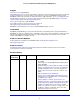
ProSecure Unified Threat Management (UTM) Appliance Figure 8. Wireless network module LED Descriptions, UTM5, UTM10, UTM25, UTM50, and UTM150 The following table describes the function of each LED. Table 2. LED descriptions UTM5, UTM10, UTM25, UTM50, and UTM150 LED Activity Description Power LED On (green) Power is supplied to the UTM. Off Power is not supplied to the UTM. Test LED On (amber) during Test mode. The UTM is initializing.
ProSecure Unified Threat Management (UTM) Appliance Table 2. LED descriptions UTM5, UTM10, UTM25, UTM50, and UTM150 (continued) LED Activity Description Off The LAN port has no link. On (green) The LAN port has detected a link with a connected Ethernet device. Blinking (green) Data is transmitted or received by the LAN port. Off The LAN port is operating at 10 Mbps. On (amber) The LAN port is operating at 100 Mbps. On (green) The LAN port is operating at 1000 Mbps.
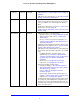
ProSecure Unified Threat Management (UTM) Appliance LED Descriptions, UTM9S, UTM25S, and their Network Modules The following table describes the function of each LED on the UTM9S and UTM25S and their network modules. Table 3. LED descriptions UTM9S and UTM25S LED Activity Description Power LED On (green) Power is supplied to the UTM. Off Power is not supplied to the UTM. Test LED On (amber) during Test mode. The UTM is initializing.
ProSecure Unified Threat Management (UTM) Appliance Table 3. LED descriptions UTM9S and UTM25S (continued) LED Activity Description Right LED Off The WAN port is operating at 10 Mbps. On (amber) The WAN port is operating at 100 Mbps. On (green) The WAN port is operating at 1000 Mbps. Off The WAN port either is not enabled or has no link to the Internet. On (green) The WAN port has a valid Internet connection.
ProSecure Unified Threat Management (UTM) Appliance Viewed from left to right, the rear panel of the UTM5, UTM10, and UTM25 contains the following components: 1. Cable security lock receptacle. 2. Console port. Port for connecting to an optional console terminal. The port has a DB9 male connector. The default baud rate is 9600 K. The pinouts are (2) Tx, (3) Rx, (5) and (7) Gnd. 3. Factory Defaults Reset button.
ProSecure Unified Threat Management (UTM) Appliance Rear Panel UTM9S and UTM25S The rear panel of the UTM9S and UTM25S includes the cable lock receptacle, the console port and console switch, the Factory Defaults reset button, the AC power connection, and the power switch. Security lock receptacle AC power receptacle Factory Defaults reset button Console switch Power switch Console port Figure 11.
ProSecure Unified Threat Management (UTM) Appliance Bottom Panels with Product Labels The product label on the bottom of the UTM’s enclosure displays factory defaults settings, regulatory compliance, and other information. The following figure shows the product label for the UTM5: Figure 12. The following figure shows the product label for the UTM10: Figure 13.
ProSecure Unified Threat Management (UTM) Appliance The following figure shows the product label for the UTM25: Figure 14. The following figure shows the product label for the UTM50: Figure 15.
ProSecure Unified Threat Management (UTM) Appliance The following figure shows the product label for the UTM150: Figure 16. The following figure shows the product label for the UTM9S: Figure 17.
ProSecure Unified Threat Management (UTM) Appliance The following figure shows the product label for the UTM25S: Figure 18. Choose a Location for the UTM The UTM is suitable for use in an office environment where it can be freestanding (on its runner feet) or mounted into a standard 19-inch equipment rack. Alternatively, you can rack-mount the UTM in a wiring closet or equipment room.
ProSecure Unified Threat Management (UTM) Appliance Use the Rack-Mounting Kit Use the mounting kit for the UTM to install the appliance in a rack. (A mounting kit is provided in the package for the multiple WAN port models.) Attach the mounting brackets using the hardware that is supplied with the mounting kit. Figure 19. Before mounting the UTM in a rack, verify that: • You have the correct screws (supplied with the installation kit). • The rack onto which you will mount the UTM is suitably located.
2. Use the Setup Wizard to Provision the UTM in Your Network 2 This chapter explains how to log in to the UTM and use the web management interface, how to use the Setup Wizard to provision the UTM in your network, and how to register the UTM with NETGEAR.
ProSecure Unified Threat Management (UTM) Appliance 4. Verify the installation. See Verify Correct Installation on page 68. 5. Register the UTM. See Register the UTM with NETGEAR on page 65. Each of these tasks is described separately in this chapter. The configuration of the WAN mode (required for multiple WAN port models), Dynamic DNS, and other WAN options is described in Chapter 3, Manually Configure Internet and WAN Settings.
ProSecure Unified Threat Management (UTM) Appliance Figure 20. 3. In the User Name field, type admin. Use lowercase letters. 4. In the Password / Passcode field, type password. Here, too, use lowercase letters. Note: The UTM user name and password are not the same as any user name or password you might use to log in to your Internet connection. 5. Click Login. The web management interface displays, showing the System Status screen.
ProSecure Unified Threat Management (UTM) Appliance Figure 21. Web Management Interface Menu Layout The following figure shows the menu at the top the UTM50 web management interface as an example.
ProSecure Unified Threat Management (UTM) Appliance 3rd level: Submenu tab (blue) 2nd level: Configuration menu link (gray) 1st level: Main navigation menu link (orange) Figure 22. Option arrow: Additional screen for submenu item The web management interface menu consists of the following components: • 1st level: Main navigation menu links.
ProSecure Unified Threat Management (UTM) Appliance • Back. Go to the previous screen (for wizards). • Search. Perform a search operation. • Cancel. Cancel the operation. • Send Now. Send a file or report. When a screen includes a table, table buttons display to let you configure the table entries. The nature of the screen determines which table buttons are shown. The following figure shows an example: Figure 24. Any of the following table buttons might display on screen: • Select All.
ProSecure Unified Threat Management (UTM) Appliance Use the Setup Wizard to Perform the Initial Configuration • Setup Wizard Step 1 of 10: LAN Settings • Setup Wizard Step 2 of 10: WAN Settings • Setup Wizard Step 3 of 10: System Date and Time • Setup Wizard Step 4 of 10: Services • Setup Wizard Step 5 of 10: Email Security • Setup Wizard Step 6 of 10: Web Security • Setup Wizard Step 7 of 10: Web Categories to Be Blocked • Setup Wizard Step 8 of 10: Email Notification • Setup Wizard Step
ProSecure Unified Threat Management (UTM) Appliance Setup Wizard Step 1 of 10: LAN Settings Figure 26. Enter the settings as explained in the following table, and then click Next to go the following screen. Note: In this first step, you are configuring the LAN settings for the UTM’s default VLAN. For more information about VLANs, see Manage Virtual LANs and DHCP Options on page 98.
ProSecure Unified Threat Management (UTM) Appliance Table 4. Setup Wizard Step 1: LAN Settings screen settings Setting Description LAN TCP/IP Setup IP Address Enter the IP address of the UTM’s default VLAN (the factory default address is 192.168.1.1). Note: Always make sure that the LAN port IP address and DMZ port IP address are in different subnets. Note: If you change the LAN IP address of the UTM’s default VLAN while being connected through the browser, you are disconnected.
ProSecure Unified Threat Management (UTM) Appliance Table 4. Setup Wizard Step 1: LAN Settings screen settings (continued) Setting Description Enable DHCP Server (continued) Primary DNS Server This setting is optional. If an IP address is specified, the UTM provides this address as the primary DNS server IP address. If no address is specified, the UTM provides its own LAN IP address as the primary DNS server IP address. Secondary DNS This setting is optional.
ProSecure Unified Threat Management (UTM) Appliance Table 4. Setup Wizard Step 1: LAN Settings screen settings (continued) Setting Description Inter VLAN Routing Enable Inter VLAN Routing This setting is optional. To ensure that traffic is routed only to VLANs for which inter-VLAN routing is enabled, select the Enable Inter VLAN Routing check box. This setting is disabled by default.
ProSecure Unified Threat Management (UTM) Appliance Enter the settings as explained in the following table, and then click Next to go the following screen. Note: Instead of manually entering the settings, you can also click the Auto Detect action button at the bottom of the screen. The autodetect process probes the WAN port for a range of connection methods and suggests one that your ISP is most likely to support. Table 5.
ProSecure Unified Threat Management (UTM) Appliance Table 5. Setup Wizard Step 2: WAN Settings screen settings (continued) Setting Description Austria (PPTP) (continued) My IP Address The IP address assigned by the ISP to make the connection with the ISP server. Server IP Address The IP address of the PPTP server. Other (PPPoE) If you have installed login software such as WinPoET or Ethernet, then your connection type is PPPoE.
ProSecure Unified Threat Management (UTM) Appliance Table 5. Setup Wizard Step 2: WAN Settings screen settings (continued) Setting Description Use Static IP Address If your ISP has assigned you a fixed (static or permanent) IP address, select the Use Static IP Address radio button and enter the following settings. IP Address The static IP address assigned to you. This address identifies the UTM to your ISP. Subnet Mask The subnet mask, which is usually provided by your ISP.
ProSecure Unified Threat Management (UTM) Appliance Enter the settings as explained in the following table, and then click Next to go the following screen. Table 6. Setup Wizard Step 3: System Date and Time screen settings Setting Description Set Time, Date, and NTP Servers Date/Time From the drop-down list, select the local time zone in which the UTM operates. The correct time zone is required in order for scheduling to work correctly.
ProSecure Unified Threat Management (UTM) Appliance Enter the settings as explained in the following table, and then click Next to go the following screen. Table 7. Setup Wizard Step 4: Services screen settings Setting Description Email SMTP POP3 IMAP SMTP scanning is enabled by default on standard service port 25. To disable any of these services, clear the POP3 scanning is enabled by default corresponding check box.
ProSecure Unified Threat Management (UTM) Appliance Setup Wizard Step 5 of 10: Email Security Figure 30. Enter the settings as explained in the following table, and then click Next to go the following screen. Table 8. Setup Wizard Step 5: Email Security screen settings Setting Description Action SMTP POP3 From the SMTP drop-down list, select one of the following actions to be taken when an infected email is detected: • Block infected email. This is the default setting.
ProSecure Unified Threat Management (UTM) Appliance Table 8. Setup Wizard Step 5: Email Security screen settings (continued) Setting Description IMAP From the IMAP drop-down list, select one of the following actions to be taken when an infected email is detected: • Delete attachment. This is the default setting. The email is not blocked, but the attachment is deleted, and a log entry is created. • Log only. Only a log entry is created. The email is not blocked, and the attachment is not deleted.
ProSecure Unified Threat Management (UTM) Appliance Table 9. Setup Wizard Step 6: Web Security screen settings Setting Description Action HTTP From the HTTP drop-down list, select one of the following actions to be taken when an infected web file or object is detected: • Delete file. This is the default setting. The web file or object is deleted, and a log entry is created. • Log only. Only a log entry is created. The web file or object is not deleted. • Quarantine file.
ProSecure Unified Threat Management (UTM) Appliance Scan screen also lets you specify HTML scanning and notification settings. For more information about these settings, see Configure Web Malware or Antivirus Scans on page 216. Setup Wizard Step 7 of 10: Web Categories to Be Blocked Figure 32.
ProSecure Unified Threat Management (UTM) Appliance Enter the settings as explained in the following table, and then click Next to go the following screen. Table 10. Setup Wizard Step 7: Web Categories to be blocked screen settings Setting Description Blocked Web Categories Select the Enable Blocking check box to enable blocking of web categories. (By default, this check box is selected.) Select the check boxes of any web categories that you want to block.
ProSecure Unified Threat Management (UTM) Appliance Setup Wizard Step 8 of 10: Email Notification Figure 33. Enter the settings as explained in the following table, and then click Next to go the following screen. Table 11. Setup Wizard Step 8: Email Notification screen settings Setting Description Administrator Email Notification Settings Show as mail sender A descriptive name of the sender for email identification purposes. For example, enter UTM_Notifications@netgear.com.
ProSecure Unified Threat Management (UTM) Appliance Setup Wizard Step 9 of 10: Signatures & Engine Figure 34. Enter the settings as explained in the following table, and then click Next to go the following screen. Table 12. Setup Wizard Step 9: Signatures & Engine screen settings Setting Description Update Settings Update From the drop-down list, select one of the following options: • Never. The pattern and firmware files are never automatically updated. • Scan engine and Signatures.
ProSecure Unified Threat Management (UTM) Appliance Table 12. Setup Wizard Step 9: Signatures & Engine screen settings (continued) Setting Description Update Frequency Specify the frequency with which the UTM checks for file updates: • Weekly. From the drop-down lists, select the weekday, hour, and minutes that the updates occur. • Daily. From the drop-down lists, select the hour and minutes that the updates occur. • Every. From the drop-down list, select the frequency with which the updates occur.
ProSecure Unified Threat Management (UTM) Appliance Register the UTM with NETGEAR • Use the Web Management Interface to Activate Licenses • Electronic Licensing • Automatic Retrieval of Licenses after a Factory Default Reset Use the Web Management Interface to Activate Licenses To receive threat management component updates and technical support, you need to register your UTM with NETGEAR.
ProSecure Unified Threat Management (UTM) Appliance Note: If you have used the 30-day trial licenses, these trial licenses are revoked once you activate the purchased service license keys. The purchased service license keys offer 1 year or 3 years of service. 4. Click Register. The UTM activates the license and registers the unit with the registration and update server. 5. Repeat Step 2 and Step 4 for additional license keys. Figure 36.
ProSecure Unified Threat Management (UTM) Appliance To change customer or VAR information after you have registered the UTM: 1. Make the changes on the Registration screen. 2. Click Update Info. The new data is saved by the registration and update server. To retrieve and display the registered information: Click Retrieve Info. The registered data is retrieved from the registration and update server.
ProSecure Unified Threat Management (UTM) Appliance Verify Correct Installation • Test Connectivity • Test HTTP Scanning Test the UTM before deploying it in a live production environment. The following instructions walk you through a couple of quick tests that are designed to ensure that your UTM is functioning correctly. Test Connectivity Verify that network traffic can pass through the UTM: 1. Ping an Internet URL. 2. Ping the IP address of a device on either side of the UTM.
ProSecure Unified Threat Management (UTM) Appliance The UTM is ready for use.
3.
ProSecure Unified Threat Management (UTM) Appliance Internet and WAN Configuration Tasks Note: For information about configuring the DSL interface of the UTM9S and UTM25S, see Appendix A, xDSL Network Module for the UTM9S and UTM25S. The information in this chapter also applies to the WAN interfaces of the UTM9S and UTM25S. Generally, five steps, three of which are optional, are required to complete the WAN Internet connection of your UTM. Complete these steps: 1.
ProSecure Unified Threat Management (UTM) Appliance To configure the WAN ports automatically for connection to the Internet: 1. Select Network Config > WAN Settings. The WAN screen displays. (The following figure shows the UTM50.) Figure 37.
ProSecure Unified Threat Management (UTM) Appliance Figure 38. 3. Click the Auto Detect button at the bottom of the screen. The autodetect process probes the WAN port for a range of connection methods and suggests one that your ISP is most likely to support. The autodetect process returns one of the following results: • If the autodetect process is successful, a status bar at the top of the screen displays the results (for example, DHCP service detected).
ProSecure Unified Threat Management (UTM) Appliance Table 13. Internet connection methods Connection method Manual data input required • DHCP (Dynamic IP) No data is required. PPPoE Login, password, account name, and domain name. PPTP Login, password, account name, your IP address, and the server IP address. Fixed (Static) IP IP address, subnet mask, and gateway IP address, and related data supplied by your ISP.
ProSecure Unified Threat Management (UTM) Appliance What to do next: • If the automatic ISP configuration is successful: You are connected to the Internet through the WAN interface that you just configured. For the multiple WAN port models, continue with the configuration process for the other WAN interfaces. If you are done with the configuration of WAN interfaces, continue with Configure the WAN Mode on page 80.
ProSecure Unified Threat Management (UTM) Appliance Figure 41. 6. If your connection is PPTP or PPPoE, your ISP requires an initial login. Enter the settings as explained in the following table: Table 14. PPTP and PPPoE settings Setting Description Austria (PPTP) If your ISP is Austria Telecom or any other ISP that uses PPTP for login, select this radio button, and enter the following settings: Account Name The account name is also known as the host name or system name.
ProSecure Unified Threat Management (UTM) Appliance Table 14. PPTP and PPPoE settings (continued) Setting Description Other (PPPoE) If you have installed login software, then your connection type is PPPoE. Select this radio button, and enter the following settings: Account Name The account name for the PPPoE connection. Domain Name The name of your ISP’s domain or your domain name if your ISP has you assigned one. You can leave this field blank.
ProSecure Unified Threat Management (UTM) Appliance Table 15. Internet IP address settings Setting Description Get Dynamically If your ISP has not assigned you a static IP address, select the Get Dynamically from from ISP ISP radio button. The ISP automatically assigns an IP address to the UTM using DHCP network protocol. Use Static IP Address Client Identifier If your ISP requires the client identifier information to assign an IP address using DHCP, select the Client Identifier check box.
ProSecure Unified Threat Management (UTM) Appliance 9. Click Apply to save any changes to the WAN ISP settings. (Or click Reset to discard any changes and revert to the previous settings.) 10. Click Test to evaluate your entries. The UTM attempts to make a connection according to the settings that you entered. 11. To verify the connection: a. Return to the WAN screen by selecting Network Config > WAN Settings. b.
ProSecure Unified Threat Management (UTM) Appliance Configure the WAN Mode • Overview of the WAN Modes • Configure Network Address Translation (All Models) • Configure Classical Routing (All Models) • Configure Auto-Rollover Mode and the Failure Detection Method (Multiple WAN Port Models) • Configure Load Balancing and Optional Protocol Binding (Multiple WAN Port Models) Overview of the WAN Modes For the multiple WAN port models, the UTM can be configured on a mutually exclusive basis for either
ProSecure Unified Threat Management (UTM) Appliance WAN interfaces, the remaining interfaces are disabled. As long as the primary link is up, all traffic is sent over the primary link. When the primary link goes down, the rollover link is brought up to send the traffic. When the primary link comes back up, traffic automatically rolls back to the original primary link.
ProSecure Unified Threat Management (UTM) Appliance WARNING: Changing the WAN mode from classical routing to NAT causes all LAN WAN and DMZ WAN inbound rules to revert to default settings. To configure NAT: 1. Select Network Config > WAN Settings > WAN Mode. The WAN Mode screen displays (see Figure 45 on page 83). 2. In the NAT (Network Address Translation) section of the screen, select the NAT radio button. 3. Click Apply to save your settings.
ProSecure Unified Threat Management (UTM) Appliance When the UTM is configured in auto-rollover mode, it uses the selected WAN failure detection method to detect the status of the primary link connection at regular intervals. Link failure is detected in one of the following ways: • DNS queries sent to a DNS server • Ping request sent to an IP address • None (no failure detection is performed) From the primary WAN interface, DNS queries or ping requests are sent to the specified IP address.
ProSecure Unified Threat Management (UTM) Appliance Note: Ensure that the backup WAN interface is configured before enabling auto-rollover mode. 3. Click Apply to save your settings. Configure the Failure Detection Method To configure the failure detection method: 1. Select Network Config > WAN Settings. The WAN screen displays (see Figure 37 on page 72). 2. Click the Edit button in the Action column of the WAN interface that you selected as the primary WAN interface.
ProSecure Unified Threat Management (UTM) Appliance Table 17. Failure detection method settings (continued) Setting Description Ping Pings are sent to a server with a public IP address. This server should not reject the ping request and should not consider ping traffic to be abusive. IP Address The IP address of the ping server. Retry Interval is The retry interval in seconds. The DNS query or ping is sent periodically after every test period. The default test period is 30 seconds.
ProSecure Unified Threat Management (UTM) Appliance Configure Load Balancing (Multiple WAN Port Models) To configure load balancing: 1. Select Network Config > WAN Settings > WAN Mode. The WAN Mode screen displays: Figure 47.
ProSecure Unified Threat Management (UTM) Appliance This load-balancing method ensures that a single WAN interface does not carry a disproportionate distribution of sessions. 3. Click Apply to save your settings. Configure Protocol Binding (Optional) To configure protocol binding and add protocol binding rules: 1. Select Network Config > Protocol Binding. The Protocol Bindings screen displays. (The following figure shows two examples in the Protocol Bindings table.) Figure 48.
ProSecure Unified Threat Management (UTM) Appliance Figure 49. 3. Configure the protocol binding settings as explained in the following table: Table 18. Add Protocol Binding screen settings Setting Description Service From the drop-down list, select a service or application to be covered by this rule. If the service or application does not appear in the list, you need to define it using the Services screen (see Outbound Rules (Service Blocking) on page 129).
ProSecure Unified Threat Management (UTM) Appliance 4. Click Apply to save your settings. The protocol binding rule is added to the Protocol Bindings table. The rule is automatically enabled, which is indicated by the ! status icon, a green circle. To edit a protocol binding: 1. On the Protocol Bindings screen (see Figure 48 on page 87), in the Protocol Bindings table, click the Edit table button to the right of the binding that you want to edit. The Edit Protocol Binding screen displays.
ProSecure Unified Threat Management (UTM) Appliance It is important that you ensure that any secondary WAN addresses are different from the primary WAN, LAN, and DMZ IP addresses that are already configured on the UTM. However, primary and secondary WAN addresses can be in the same subnet. The following is an example of correctly configured IP addresses on a multiple WAN port model: • Primary WAN1 IP address. 10.121.0.1 with subnet 255.255.255.0 • Secondary WAN1 IP address. 10.121.26.
ProSecure Unified Threat Management (UTM) Appliance 5. Click the Add table button in the rightmost column to add the secondary IP address to the List of Secondary WAN addresses table. Repeat Step 4 and Step 5 for each secondary IP address that you want to add to the List of Secondary WAN addresses table. To delete one or more secondary addresses: 1.
ProSecure Unified Threat Management (UTM) Appliance To configure DDNS: 1. Select Network Config > Dynamic DNS. The Dynamic DNS screen displays (see the following figure). The WAN Mode section onscreen reports the currently configured WAN mode (for example, Single Port WAN1, Load Balancing, or Auto Rollover). Only those options that match the configured WAN mode are accessible onscreen. 2. Click the submenu tab for your DDNS service provider: • Dynamic DNS for DynDNS.
ProSecure Unified Threat Management (UTM) Appliance Figure 52. 4. Access the website of the DDNS service provider, and register for an account (for example, for DynDNS.org, go to http://www.dyndns.com/). 5. Configure the DDNS service settings as explained in the following table: Table 19. DNS service settings Setting Description WAN (Dynamic DNS Status: ...) or WAN1 (Dynamic DNS Status: ...) Change DNS to Select the Yes radio button to enable the DDNS service.
ProSecure Unified Threat Management (UTM) Appliance Set the UTM’s MAC Address and Configure Advanced WAN Options The advanced options include configuring the maximum transmission unit (MTU) size, the port speed, and the UTM’s MAC address, and setting a rate limit on the traffic that is forwarded by the UTM. Note: You can also configure the failure detection method for the auto-rollover mode on the WAN Advanced Options screen for the corresponding WAN interface.
ProSecure Unified Threat Management (UTM) Appliance Figure 53. 4. Enter the settings as explained in the following table: Table 20. Advanced WAN settings Setting Description MTU Size Make one of the following selections: Default Select the Default radio button for the normal maximum transmit unit (MTU) value. For most Ethernet networks, this value is 1500 bytes, or 1492 bytes for PPPoE connections. Custom Select the Custom radio button, and enter an MTU value in the Bytes field.
ProSecure Unified Threat Management (UTM) Appliance Table 20. Advanced WAN settings (continued) Setting Description Speed In most cases, the UTM can automatically determine the connection speed of the WAN port of the device (modem or router) that provides the WAN connection. If you cannot establish an Internet connection, you might need to select the port speed manually. If you know the Ethernet port speed of the modem or router, select it from the drop-down list.
ProSecure Unified Threat Management (UTM) Appliance Table 20. Advanced WAN settings (continued) Setting Description WAN Connection Speed Upload From the drop-down list, select the maximum upload speed that is provided by your ISP. You can select from 56 Kbps to 1 Gbps, or you can select Custom and enter the speed in Kbps in the field below the drop-down list. WAN Connection Speed Download From the drop-down list, select the maximum download speed that is provided by your ISP.
4. LAN Configuration 4 This chapter describes how to configure the advanced LAN features of your UTM. This chapter contains the following sections: • Manage Virtual LANs and DHCP Options • Configure Multihome LAN IP Addresses on the Default VLAN • Manage Groups and Hosts (LAN Groups) • Configure and Enable the DMZ Port • Manage Routing Note: The initial LAN configuration of the UTM’s default VLAN 1 is described in Chapter 2, Use the Setup Wizard to Provision the UTM in Your Network.
ProSecure Unified Threat Management (UTM) Appliance A virtual LAN (VLAN) is a local area network with a definition that maps workstations on some basis other than geographic location (for example, by department, type of user, or primary application). To enable traffic to flow between VLANs, traffic needs to go through a router, just as if the VLANs were on two separate LANs.
ProSecure Unified Threat Management (UTM) Appliance • When a port receives an untagged packet, this packet is forwarded to a VLAN based on the PVID. • When a port receives a tagged packet, this packet is forwarded to a VLAN based on the ID that is extracted from the tagged packet. When you create a VLAN profile, assign LAN ports to the VLAN, and enable the VLAN, the LAN ports that are members of the VLAN can send and receive both tagged and untagged packets.
ProSecure Unified Threat Management (UTM) Appliance Figure 54. For each VLAN profile, the following fields display in the VLAN Profiles table: • Check box. Allows you to select the VLAN profile in the table. • Status icon. Indicates the status of the VLAN profile: - Green circle. The VLAN profile is enabled. - Gray circle. The VLAN profile is disabled. • Profile Name. The unique name assigned to the VLAN profile. • VLAN ID. The unique ID (or tag) assigned to the VLAN profile. • Subnet IP.
ProSecure Unified Threat Management (UTM) Appliance DHCP Server The default VLAN (VLAN 1) has the DHCP server option enabled by default, allowing the UTM to assign IP, DNS server, WINS server, and default gateway addresses to all computers connected to the UTM’s LAN. The assigned default gateway address is the LAN address of the UTM. IP addresses are assigned to the attached computers from a pool of addresses that you need to specify.
ProSecure Unified Threat Management (UTM) Appliance configuration in auto-rollover mode with route diversity (that is, with two different ISPs) and you cannot ensure that the DNS server is available after a rollover has occurred. LDAP Server A Lightweight Directory Access Protocol (LDAP) server allows a user to query and modify directory services that run over TCP/IP. For example, clients can query email addresses, contact information, and other service information using an LDAP server.
ProSecure Unified Threat Management (UTM) Appliance 2. Either select an entry from the VLAN Profiles table and click the corresponding Edit table button, or add a VLAN profile by clicking the Add table button under the VLAN Profiles table. The Edit VLAN Profile screen displays. The following figure shows the Edit VLAN Profile screen for the UTM with four ports in the Port Membership section.
ProSecure Unified Threat Management (UTM) Appliance 3. Enter the settings as explained in the following table: Table 21. Edit VLAN Profile screen settings Setting Description VLAN Profile Profile Name Enter a unique name for the VLAN profile. Note: You can also change the profile name of the default VLAN. VLAN ID Enter a unique ID number for the VLAN profile. No two VLANs can have the same VLAN ID number. Note: You can enter VLAN IDs from 2 to 4093.
ProSecure Unified Threat Management (UTM) Appliance Table 21. Edit VLAN Profile screen settings (continued) Setting Description Enable DHCP Server Select the Enable DHCP Server radio button to enable the UTM to function as a Dynamic Host Configuration Protocol (DHCP) server, providing TCP/IP configuration for all computers connected to the VLAN. Enter the following settings: Domain Name This setting is optional. Enter the domain name of the UTM. Starting IP Address Enter the starting IP address.
ProSecure Unified Threat Management (UTM) Appliance Table 21. Edit VLAN Profile screen settings (continued) Setting Description Enable LDAP information To enable the DHCP server to provide Lightweight Directory Access Protocol (LDAP) server information, select the Enable LDAP information check box. Enter the following settings. Note: The LDAP settings that you specify as part of the VLAN profile are used only for SSL VPN and UTM authentication, but not for web and email security.
ProSecure Unified Threat Management (UTM) Appliance Note: When you have completed the LAN setup, all outbound traffic is allowed and all inbound traffic is discarded except responses to requests from the LAN side. For information about how to change these default traffic rules, see Chapter 5, Firewall Protection. To edit a VLAN profile: 1. On the LAN Setup screen (see Figure 55 on page 103), click the Edit button in the Action column for the VLAN profile that you want to modify.
ProSecure Unified Threat Management (UTM) Appliance Figure 57. 3. From the MAC Address for VLANs drop-down list, select Unique. (The default is Same.) 4. As an option, you can disable the broadcast of ARP packets for the default VLAN by clearing the Enable ARP Broadcast check box. (The broadcast of ARP packets is enabled by default for the default VLAN.) If you choose to keep the broadcast of ARP enabled, you can enter an ARP refresh rate in the Set Refresh Rate field. The default setting is 180 seconds.
ProSecure Unified Threat Management (UTM) Appliance The following is an example of correctly configured IP addresses on a multiple WAN port model: • WAN1 IP address. 10.0.0.1 with subnet 255.0.0.0 • WAN2 IP address. 20.0.0.1 with subnet 255.0.0.0 • DMZ IP address. 192.168.10.1 with subnet 255.255.255.0 • Primary LAN IP address. 192.168.1.1 with subnet 255.255.255.0 • Secondary LAN IP address. 192.168.20.1 with subnet 255.255.255.0 To add a secondary LAN IP address: 1.
ProSecure Unified Threat Management (UTM) Appliance To edit a secondary LAN IP address: 1. On the LAN Multi-homing screen (see the previous screen), click the Edit button in the Action column for the secondary IP address that you want to modify. The Edit Secondary LAN IP address screen displays. 2. Modify the IP address or subnet mask, or both. 3. Click Apply to save your settings. To delete one or more secondary LAN IP addresses: 1.
ProSecure Unified Threat Management (UTM) Appliance These are some advantages of the network database: • Generally, you do not need to enter an IP address or a MAC address. Instead, you can just select the name of the desired computer or device. • There is no need to reserve an IP address for a computer in the DHCP server.
ProSecure Unified Threat Management (UTM) Appliance Figure 59. The Known PCs and Devices table lists the entries in the network database. For each computer or device, the following fields display: • Check box. Allows you to select the computer or device in the table. • Name. The name of the computer or device. For computers that do not support the NetBIOS protocol, the name is displayed as Unknown (you can edit the entry manually to add a meaningful name).
ProSecure Unified Threat Management (UTM) Appliance Add Computers or Devices to the Network Database To add computers or devices manually to the network database: 1. In the Add Known PCs and Devices section of the LAN Groups screen (see the previous figure), enter the settings as explained in the following table: Table 22. Known PCs and devices settings Setting Description Name Enter the name of the computer or device.
ProSecure Unified Threat Management (UTM) Appliance Figure 60. 2. Modify the settings as explained in Table 22 on page 114. 3. Click Apply to save your settings in the Known PCs and Devices table. Delete Computers or Devices from the Network Database To delete one or more computers or devices from the network database: 1.
ProSecure Unified Threat Management (UTM) Appliance Figure 61. 3. Select the radio button next to the group name that you want to edit. 4. Type a new name in the field. The maximum number of characters is 15; spaces and double quotes (") are not allowed. 5. Repeat Step 3 and Step 4 for any other group names. 6. Click Apply to save your settings.
ProSecure Unified Threat Management (UTM) Appliance Configure and Enable the DMZ Port The demilitarized zone (DMZ) is a network that, by default, has fewer firewall restrictions than the LAN. The DMZ can be used to host servers (such as a web server, FTP server, or email server) and provide public access to them. The rightmost LAN port on the UTM can be dedicated as a hardware DMZ port to provide services to the Internet safely without compromising security on your LAN.
ProSecure Unified Threat Management (UTM) Appliance Figure 62. 2. Enter the settings as explained in the following table: Table 23. DMZ Setup screen settings Setting Description DMZ Port Setup Do you want to enable DMZ Port? Select one of the following radio buttons: • Yes. Enables you to configure the DMZ port settings. Fill in the IP Address and Subnet Mask fields. • No. Allows you to disable the DMZ port after you have configured it. IP Address Enter the IP address of the DMZ port.
ProSecure Unified Threat Management (UTM) Appliance Table 23. DMZ Setup screen settings (continued) Setting Description DHCP Disable DHCP Server If another device on your network is the DHCP server for the VLAN, or if you will configure the network settings of all of your computers manually, select the Disable DHCP Server radio button to disable the DHCP server. By default, this radio button is not selected, and the DHCP server is enabled.
ProSecure Unified Threat Management (UTM) Appliance Table 23. DMZ Setup screen settings (continued) Setting Description Enable LDAP information To enable the DHCP server to provide Lightweight Directory Access Protocol (LDAP) server information, select the Enable LDAP information check box. Enter the following settings: LDAP Server The IP address or name of the LDAP server. Search Base The search objects that specify the location in the directory tree from which the LDAP search begins.
ProSecure Unified Threat Management (UTM) Appliance Manage Routing • Configure Static Routes • Configure Routing Information Protocol • Static Route Example Static routes provide additional routing information to your UTM. Under normal circumstances, the UTM has adequate routing information after it has been configured for Internet access, and you do not need to configure additional static routes.
ProSecure Unified Threat Management (UTM) Appliance Figure 64. 3. Enter the settings as explained in the following table: Table 24. Add Static Route screen settings Setting Description Route Name The route name for the static route (for purposes of identification and management). Active To make the static route effective, select the Active check box. Note: A route can be added to the table and made inactive if not needed.
ProSecure Unified Threat Management (UTM) Appliance To edit a static route that is in the Static Routes table: 1. On the Routing screen (see Figure 63 on page 121), click the Edit button in the Action column for the route that you want to modify. The Edit Static Route screen displays. This screen is identical to the Add Static Route screen (see the previous screen). 2. Modify the settings as explained in the previous table. 3. Click Apply to save your settings. To delete one or more routes: 1.
ProSecure Unified Threat Management (UTM) Appliance Figure 65. 3. Enter the settings as explained in the following table: Table 25. RIP Configuration screen settings Setting Description RIP RIP Direction From the RIP Direction drop-down list, select the direction in which the UTM sends and receives RIP packets: • None. The UTM neither advertises its route table, nor accepts any RIP packets from other routers. This effectively disables RIP, and is the default setting. • In Only.
ProSecure Unified Threat Management (UTM) Appliance Table 25. RIP Configuration screen settings (continued) Setting Description RIP Version By default, the RIP version is set to Disabled. From the RIP Version drop-down list, select the version: • RIP-1. Classful routing that does not include subnet information. This is the most commonly supported version. • RIP-2. Routing that supports subnet information. Both RIP-2B and RIP-2M send the routing data in RIP-2 format: - RIP-2B.
ProSecure Unified Threat Management (UTM) Appliance Static Route Example In this example, we assume the following: • The UTM’s primary Internet access is through a cable modem to an ISP. • The UTM is on a local LAN with IP address 192.168.1.100. • The UTM connects to a remote network where you need to access a device. • The LAN IP address of the remote network is 134.177.0.0.
5. Firewall Protection 5 This chapter describes how to use the firewall features of the UTM to protect your network.
ProSecure Unified Threat Management (UTM) Appliance Administrator Tips Consider the following operational items: 1. As an option, you can enable remote management if you have to manage distant sites from a central location (see Configure Authentication Domains, Groups, and Users on page 380 and Configure Remote Management Access on page 438). 2.
ProSecure Unified Threat Management (UTM) Appliance A firewall has two default rules, one for inbound traffic and one for outbound. The default rules of the UTM are: • Inbound. Block all access from outside except responses to requests from the LAN side. • Outbound. Allow all access from the LAN side to the outside. The firewall rules for blocking and allowing traffic on the UTM can be applied to LAN WAN traffic, DMZ WAN traffic, and LAN DMZ traffic. Table 26.
ProSecure Unified Threat Management (UTM) Appliance WARNING: Allowing inbound services opens security holes in your UTM. Enable only those ports that are necessary for your network. The following table describes the fields that define the rules for outbound traffic and that are common to most Outbound Service screens (see Figure 68 on page 141, Figure 71 on page 144, and Figure 74 on page 147).
ProSecure Unified Threat Management (UTM) Appliance Table 27. Outbound rules overview (continued) Setting Description Outbound Rules LAN Users The settings that determine which computers on your network are LAN WAN rules affected by this rule. The options are: LAN DMZ rules • Any. All computers and devices on your LAN. • Single address. Enter the required address in the Start field to apply the rule to a single device on your LAN. • Address range.
ProSecure Unified Threat Management (UTM) Appliance Table 27. Outbound rules overview (continued) Setting Description Outbound Rules QoS Profile The priority assigned to IP packets of this service. The priorities are LAN WAN rules defined by Type of Service (ToS) in the Internet Protocol Suite DMZ WAN rule standards, RFC 1349. The QoS profile determines the priority of a service, which, in turn, determines the quality of that service for the traffic passing through the firewall.
ProSecure Unified Threat Management (UTM) Appliance Table 27. Outbound rules overview (continued) Setting Description Outbound Rules Application Control Select an application control profile to allow, block, or log traffic for entire categories of applications, for individual applications, or for a combination of both. The application control profile applies only to traffic that is covered by this rule.
ProSecure Unified Threat Management (UTM) Appliance • Local computers need to access the local server using the computers’ local LAN address. Attempts by local computers to access the server using the external WAN IP address will fail. Note: See Configure Port Triggering on page 183 for yet another way to allow certain types of inbound traffic that would otherwise be blocked by the firewall. Note: The UTM always blocks denial of service (DoS) attacks.
ProSecure Unified Threat Management (UTM) Appliance Table 28. Inbound rules overview Setting Description Inbound Rules Service (also referred to as Service Name) The service or application to be covered by this rule. If the service or All rules application does not display in the list, you need to define it using the Services screen (see Add Customized Services on page 163).
ProSecure Unified Threat Management (UTM) Appliance Table 28. Inbound rules overview (continued) Setting Description Inbound Rules LAN Users The settings that determine which computers on your network are LAN WAN rules affected by this rule. The options are: LAN DMZ rules • Any. All computers and devices on your LAN. • Single address. Enter the required address in the Start field to apply the rule to a single device on your LAN. • Address range.
ProSecure Unified Threat Management (UTM) Appliance Table 28. Inbound rules overview (continued) Setting Description Inbound Rules QoS Profile The priority assigned to IP packets of this service. The priorities are defined by Type of Service (ToS) in the Internet Protocol Suite standards, RFC 1349. The QoS profile determines the priority of a service which, in turn, determines the quality of that service for the traffic passing through the firewall.
ProSecure Unified Threat Management (UTM) Appliance Table 28. Inbound rules overview (continued) Setting Description Inbound Rules Application Control Select an application control profile to allow, block, or log traffic for LAN WAN rules entire categories of applications, for individual applications, or for a DMZ WAN rules combination of both. The application control profile applies only to traffic that is covered by this rule.
ProSecure Unified Threat Management (UTM) Appliance For any traffic attempting to pass through the firewall, the packet information is subjected to the rules in the order shown in the Rules table, beginning at the top and proceeding to the bottom. In some cases, the order of precedence of two or more rules might be important in determining the disposition of a packet. For example, you should place the most strict rules at the top (those with the most specific services or addresses).
ProSecure Unified Threat Management (UTM) Appliance To change an existing outbound or inbound service rule: In the Action column to the right of to the rule, click one of the following table buttons: • Edit. Allows you to make any changes to the definition of an existing rule.
ProSecure Unified Threat Management (UTM) Appliance Figure 68. 2. Enter the settings as explained in Table 27 on page 130. 3. Click Apply to save your changes. The new rule is now added to the Outbound Services table. Create LAN WAN Inbound Service Rules The Inbound Services table lists all existing rules for inbound traffic. If you have not defined any rules, no rules are listed. By default, all inbound traffic (from the Internet to the LAN) is blocked.
ProSecure Unified Threat Management (UTM) Appliance Figure 69. 2. Enter the settings as explained in Table 28 on page 135. 3. Click Apply to save your changes. The new rule is now added to the Inbound Services table. Configure DMZ WAN Rules • Create DMZ WAN Outbound Service Rules • Create DMZ WAN Inbound Service Rules The firewall rules for traffic between the DMZ and the Internet are configured on the DMZ WAN Rules screen. The default outbound policy is to block all traffic from and to the Internet.
ProSecure Unified Threat Management (UTM) Appliance adding outbound services rules (see Create DMZ WAN Outbound Service Rules on page 144). To access the DMZ WAN Rules screen, select Network Security > Firewall > DMZ WAN Rules. The DMZ WAN Rules screen displays. (The following figure shows some rules as an example.) Figure 70. To change an existing outbound or inbound service rule: In the Action column to the right of to the rule, click one of the following table buttons: • Edit.
ProSecure Unified Threat Management (UTM) Appliance Create DMZ WAN Outbound Service Rules You can change the default outbound policy or define rules that specify exceptions to the default outbound policy. By adding custom rules, you can block or allow access based on the service or application, source or destination IP addresses, and time of day. An outbound rule can block or allow traffic between the DMZ and any external WAN IP address according to the schedule created in the Schedule screen.
ProSecure Unified Threat Management (UTM) Appliance To create an inbound DMZ WAN service rule: 1. In the DMZ WAN Rules screen, click the Add table button under the Inbound Services table. The Add DMZ WAN Inbound Service screen displays: Figure 72. 2. Enter the settings as explained in Table 28 on page 135. 3. Click Apply to save your changes. The new rule is now added to the Inbound Services table.
ProSecure Unified Threat Management (UTM) Appliance To access the LAN DMZ Rules screen and to change an existing outbound or inbound service rule, select Network Security > Firewall > LAN DMZ Rules. The LAN DMZ Rules screen displays: Figure 73. In the Action column to the right of to the rule, click one of the following table buttons: • Edit. Allows you to make any changes to the rule definition of an existing rule.
ProSecure Unified Threat Management (UTM) Appliance Create LAN DMZ Outbound Service Rules You can change the default outbound policy or define rules that specify exceptions to the default outbound policy. By adding custom rules, you can block or allow access based on the service or application, source or destination IP addresses, and time of day. An outbound rule can block or allow traffic between the DMZ and any internal LAN IP address according to the schedule created in the Schedule screen.
ProSecure Unified Threat Management (UTM) Appliance Figure 75. 2. Enter the settings as explained in Table 28 on page 135. 3. Click Apply to save your changes. The new rule is now added to the Inbound Services table.
ProSecure Unified Threat Management (UTM) Appliance Figure 76. LAN WAN Inbound Rule: Allow Videoconference from Restricted Addresses If you want to allow incoming videoconferencing to be initiated from a restricted range of outside IP addresses, such as from a branch office, you can create an inbound rule (see the following figure). In the example, CU-SeeMe connections are allowed only from a specified range of external IP addresses.
ProSecure Unified Threat Management (UTM) Appliance Figure 77. LAN WAN or DMZ WAN Inbound Rule: Set Up One-to-One NAT Mapping In this example, multi-NAT is configured to support multiple public IP addresses on one WAN interface. An inbound rule configures the UTM to host an additional public IP address and associate this address with a web server on the LAN. (For information about how to configure a secondary WAN IP address, see Configure Secondary WAN Addresses on page 89.
ProSecure Unified Threat Management (UTM) Appliance Tip: If you arrange with your ISP to have more than one public IP address for your use, you can use the additional public IP addresses to map to servers on your LAN or DMZ. One of these public IP addresses is used as the primary IP address of the router that provides Internet access to your LAN computers through NAT. The other addresses are available to map to your servers. To configure the UTM for additional IP addresses: 1.
ProSecure Unified Threat Management (UTM) Appliance 6. In the Send to LAN Server field, enter the local IP address of your web server computer (192.168.1.2 in this example). 7. For the multiple WAN port models only: From the WAN Destination IP Address drop-down list, select the web server (the simulated 10.1.0.52 address in this example) that you have defined on a WAN Secondary Addresses screen (see Configure Secondary WAN Addresses on page 89).
ProSecure Unified Threat Management (UTM) Appliance WARNING: For security, NETGEAR strongly recommends that you avoid creating an exposed host. When a computer is designated as the exposed host, it loses much of the protection of the firewall and is exposed to many exploits from the Internet. If compromised, the computer can be used to attack your network. Outbound Rule Example Outbound rules let you prevent users from using applications such as Instant Messenger, Real Audio, or other nonessential sites.
ProSecure Unified Threat Management (UTM) Appliance Configure Other Firewall Features • VLAN Rules • Attack Checks, VPN Pass-through, and Multicast Pass-through • Set Session Limits • Manage the Application Level Gateway for SIP Sessions and VPN Scanning You can configure global VLAN rules, configure attack checks, set session limits, and manage the application level gateway (ALG) for SIP sessions.
ProSecure Unified Threat Management (UTM) Appliance Figure 82. 3. Enter the settings as explained in the following table. Table 29. Add VLAN-VLAN Service screen settings Setting Description Service The service or application to be covered by this rule. If the service or application does not display in the list, you need to define it using the Services screen (see Add Customized Services on page 163).
ProSecure Unified Threat Management (UTM) Appliance Table 29. Add VLAN-VLAN Service screen settings (continued) Setting Description User Allowed The settings that determine which user or group on the network is affected by this rule. You can select a local user, local group, or customer group. To create a custom group, select + Create New from the Users Allowed drop-down list. (You can find the + Create New link under the Custom Groups heading.) The Add Custom Group pop-up screen displays.
ProSecure Unified Threat Management (UTM) Appliance Attack Checks, VPN Pass-through, and Multicast Pass-through The Attack Checks screen allows you to specify whether the UTM should be protected against common attacks in the DMZ, LAN, and WAN networks, and lets you configure VPN pass-through and multicast pass-through. The various types of attack checks are listed on the Attack Checks screen and defined in Table 30 on page 157. To enable the appropriate attack checks for your network environment: 1.
ProSecure Unified Threat Management (UTM) Appliance Table 30. Attack Checks screen settings (continued) Setting Description LAN Security Checks Block UDP flood Select the Block UDP flood check box to prevent the UTM from accepting more than 20 simultaneous, active User Datagram Protocol (UDP) connections from a single device on the LAN. By default, the Block UDP flood check box is cleared.
ProSecure Unified Threat Management (UTM) Appliance Figure 84. 2. In the Multicast Pass through section of the screen, select the Yes radio button to enable multicast pass-through. (By default the Yes radio button is enabled.) When you enable multicast pass-through, an Internet Group Management Protocol (IGMP) proxy is enabled for the upstream (WAN) and downstream (LAN) interfaces.
ProSecure Unified Threat Management (UTM) Appliance To delete one or more multicast source addresses: 1. In the Alternate Networks table, select the check box to the left of each address that you want to delete, or click the Select All table button to select all addresses. 2. Click the Delete table button. Set Session Limits The session limits feature allows you to specify the total number of sessions that are allowed, per user, over an IP connection across the UTM.
ProSecure Unified Threat Management (UTM) Appliance Table 31. Session Limit screen settings (continued) Setting Description User Limit Enter a number to indicate the user limit. If the User Limit Parameter is set to Percentage of Max Sessions, the number specifies the maximum number of sessions that are allowed from a single-source device as a percentage of the total session connection capacity of the UTM. (The session limit is per-device based.
ProSecure Unified Threat Management (UTM) Appliance Figure 86. 2. In the ALG section, select the Enable SIP ALG check box. 3. In the ALG section, click Apply to save your settings. 4. In the VPN scan section, select the Enable VPN scan check box. 5. In the VPN scan section, click Apply to save your settings.
ProSecure Unified Threat Management (UTM) Appliance • QoS profiles. A Quality of Service (QoS) profile defines the relative priority of an IP packet for traffic that matches the firewall rule. For information about creating QoS profiles, see Create Quality of Service Profiles on page 169. • Bandwidth profiles. A bandwidth profile allocates and limits traffic bandwidth for the LAN users to which a firewall rule is applied.
ProSecure Unified Threat Management (UTM) Appliance To add a customized service: 1. Select Network Security > Services. The Services screen displays. The Custom Services table shows the user-defined services. (The following figure shows some examples.) Figure 87. 2. In the Add Customer Service section of the screen, enter the settings as explained in the following table: Table 32.
ProSecure Unified Threat Management (UTM) Appliance To edit a service: 1. In the Custom Services table, click the Edit table button to the right of the service that you want to edit. The Edit Service screen displays: Figure 88. 2. Modify the settings that you wish to change (see the previous table). 3. Click Apply to save your changes. The modified service is displayed in the Custom Services table. To delete one or more services: 1.
ProSecure Unified Threat Management (UTM) Appliance Figure 89. 2. Under the Custom Service Group table, click the Add table button. The Add Service Group screen displays: Figure 90. 3. In the Name field, enter a name for the service. 4. Use the move buttons (<< and >>) to move services between the Available Services field and the List of Selected Services field to specify the services that you want to be part of the group. 5. Click Apply to save your changes.
ProSecure Unified Threat Management (UTM) Appliance Create IP Groups An IP group contains a collection of individual IP addresses that do not need to be within the same IP address range. You specify an IP group as either a LAN group or WAN group. You use the group as a firewall object to which you apply a firewall rule, that is, you select the group from the LAN Users or WAN Users drop-down list on a screen on which you add or edit a firewall rule. To create an IP group: 1.
ProSecure Unified Threat Management (UTM) Appliance Figure 92. 5. In the IP Address fields, type an IP address. 6. Click the Add table button to add the IP address to the IP Addresses Grouped table. 7. Repeat the previous two steps to add more IP addresses to the IP Addresses Grouped table. 8. Click the Edit table button to return to IP Groups screen. To edit a service group: 1. In the Custom IP Groups table, click the Edit table button to the right of the IP group that you want to edit.
ProSecure Unified Threat Management (UTM) Appliance Create Quality of Service Profiles A Quality of Service (QoS) profile defines the relative priority of an IP packet when multiple connections are scheduled for simultaneous transmission on the UTM. A QoS profile becomes active only when it is associated with a nonblocking inbound or outbound firewall rule, and traffic matching the firewall rule is processed by the UTM.
ProSecure Unified Threat Management (UTM) Appliance Figure 93. The screen displays the List of QoS Profiles table with the user-defined profiles. 2. Under the List of QoS Profiles table, click the Add table button. The Add QoS Profile screen displays: Figure 94. 3. Enter the settings as explained in the following table. Note: This document assumes that you are familiar with QoS concepts such QoS priority queues, IP precedence, DHCP, and their values. Table 33.
ProSecure Unified Threat Management (UTM) Appliance Table 33. Add QoS Profile screen settings (continued) Setting Description QoS From the QoS drop-down list, select one of the following traffic classification methods: • IP Precedence. A legacy method that sets the priority in the ToS byte of an IP header. • DSCP. A method that sets the Differentiated Services Code Point (DSCP) in the Differentiated Services (DS) field (which is the same as the ToS byte) of an IP header.
ProSecure Unified Threat Management (UTM) Appliance When a new connection is established by a device, the device locates the firewall rule corresponding to the connection. • If the rule has a bandwidth profile specification, the device creates a bandwidth class in the kernel. • If multiple connections correspond to the same firewall rule, the connections all share the same bandwidth class. An exception occurs for an individual bandwidth profile if the classes are per-source IP address classes.
ProSecure Unified Threat Management (UTM) Appliance Figure 96. 3. Enter the settings as explained in the following table: Table 34. Add Bandwidth Profile screen settings Setting Description Profile Name A descriptive name of the bandwidth profile for identification and management purposes. Direction From the Direction drop-down list, select the traffic direction for the bandwidth profile: • Outbound Traffic. The bandwidth profile is applied only to outbound traffic.
ProSecure Unified Threat Management (UTM) Appliance Table 34. Add Bandwidth Profile screen settings (continued) Setting Description Policy Type From the Policy Type drop-down list, select how the policy is applied when it is assigned to multiple firewall rules: • Per Policy. The policy limits apply to each firewall rule separately. For example, an outbound maximum bandwidth of 25,000 Kbps would apply to each firewall rule to which the policy is assigned. • All Policies.
ProSecure Unified Threat Management (UTM) Appliance both downloaded and uploaded traffic. When applied to multiple firewall rules, a single profile can be applied to each firewall rule separately, or to all firewall rules together. After you have created a traffic meter profile, you can assign the profile to firewall rules and application control profiles on the following screens: • Add LAN WAN Outbound Services screen (see Figure 68 on page 141).
ProSecure Unified Threat Management (UTM) Appliance Figure 98. 3. Enter the settings as explained in the following table: Table 35. Add Traffic Meter Profile screen settings Setting Description Profile Name A descriptive name of the traffic meter profile for identification and management purposes. Direction From the Direction drop-down list, select the traffic direction for the bandwidth profile: • Download only. The traffic meter profile is applied only to downloaded traffic.
ProSecure Unified Threat Management (UTM) Appliance 4. Click Apply to save your settings. The new traffic meter profile is added to the List of Traffic Meter Profiles table. You now can select the profile when you create or change a firewall rule. To edit a traffic meter profile: 1. In the List of Traffic Meter Profiles table, click the Edit table button to the right of the traffic meter profile that you want to edit. The Edit Traffic Meter Profile screen displays. 2.
ProSecure Unified Threat Management (UTM) Appliance Figure 100. 3. Enter the settings as explained in the following table: Table 36. Add Schedule screen settings Setting Description Profile Name A name of the schedule for identification and management purposes. Description A description to further help identification for management purposes. Scheduled Days Select one of the following radio buttons: • All Days. The schedule is in effect all days of the week. • Specific Days.
ProSecure Unified Threat Management (UTM) Appliance Table 36. Add Schedule screen settings (continued) Setting Description Scheduled Time of Day Select one of the following radio buttons: • All Day. The schedule is in effect all hours of the selected day or days. • Specific Times. The schedule is in effect only during specific periods of the selected day or days.
ProSecure Unified Threat Management (UTM) Appliance To enable MAC filtering and add MAC addresses to be permitted or blocked: 1. Select Network Security > Address Filter. The Address Filter submenu tabs display, with the Source MAC Filter screen in view. (The following figure shows one address in the MAC Addresses table as an example.) Figure 101. 2. In the MAC Filtering Enable section, select the Yes radio button. 3.
ProSecure Unified Threat Management (UTM) Appliance Set Up IP/MAC Bindings IP/MAC binding allows you to bind an IP address to a MAC address and the other way around. Some computers or devices are configured with static addresses. To prevent users from changing their static IP addresses, the IP/MAC binding feature needs to be enabled on the UTM.
ProSecure Unified Threat Management (UTM) Appliance Figure 102. 2. Enter the settings as explained in the following table: Table 37. IP/MAC Binding screen settings Setting Description Email IP/MAC Violations Do you want to Select one of the following radio buttons: enable E-mail Logs • Yes. IP/MAC binding violations are emailed. for IP/MAC Binding • No. IP/MAC binding violations are not emailed.
ProSecure Unified Threat Management (UTM) Appliance To edit an IP/MAC binding: 1. In the IP/MAC Bindings table, click the Edit table button to the right of the IP/MAC binding that you want to edit. The Edit IP/MAC Binding screen displays. 2. Modify the settings that you wish to change (see the previous table). 3. Click Apply to save your changes. The modified IP/MAC binding displays in the IP/MAC Bindings table. To remove one or more IP/MAC bindings from the table: 1.
ProSecure Unified Threat Management (UTM) Appliance To add a port-triggering rule: 1. Select Network Security > Port Triggering. The Port Triggering screen displays. (The following figure shows a rule in the Port Triggering Rule table as an example.) Figure 103. 2. In the Add Port Triggering Rule section, enter the settings as explained in the following table: Table 38.
ProSecure Unified Threat Management (UTM) Appliance To edit a port-triggering rule: 1. In the Port Triggering Rules table, click the Edit table button to the right of the port-triggering rule that you want to edit. The Edit Port Triggering Rule screen displays. 2. Modify the settings that you wish to change (see the previous table). 3. Click Apply to save your changes. The modified port-triggering rule is displayed in the Port Triggering Rules table.
ProSecure Unified Threat Management (UTM) Appliance Configure Universal Plug and Play The Universal Plug and Play (UPnP) feature enables the UTM to discover and configure devices automatically when it searches the LAN and WAN. 1. Select Security > UPnP. The UPnP screen displays: Figure 105. The UPnP Portmap Table in the lower part of the screen shows the IP addresses and other settings of UPnP devices that have accessed the UTM and that have been automatically detected by the UTM: • Active.
ProSecure Unified Threat Management (UTM) Appliance Enable and Configure the Intrusion Prevention System The intrusion prevention system (IPS) of the UTM monitors all network traffic to detect, in real time, distributed denial-of-service (DDoS) attacks, network attacks, and port scans, and to protect your network from such intrusions. You can set up alerts, block source IP addresses from which port scans are initiated, and drop traffic that carries attacks.
ProSecure Unified Threat Management (UTM) Appliance Table 39. IPS screen settings (continued) Setting Description Detect DDoS Detect the action that is taken when the UTM detects a DDoS attack: • Alert. An alert is emailed to the administrator that is specified on the Email Notification screen. • Disable. DDoS attack detection is disabled. • Block Source IP for. The IP address of the attacking computer is blocked for the duration that you specify in the Seconds field. The default setting is 300 seconds.
ProSecure Unified Threat Management (UTM) Appliance Figure 106.
ProSecure Unified Threat Management (UTM) Appliance Figure 107. IPS, screen 2 of 2 4. Click Apply to save your settings. The following table explains some of the less familiar attack names in the IPS: Table 40. IPS: uncommon attack names Attack Name Description Web Web-Misc Detects some specific web attack tools, such as the fingerprinting tool and the password-cracking tool.
ProSecure Unified Threat Management (UTM) Appliance Table 40. IPS: uncommon attack names (continued) Attack Name Description Web-Attacks Detects the web attacks that cannot be placed under other web categories, such as DoS and overflow attacks against specific web services. These web services include IMail Web Calendaring, ZixForum, ScozNet, ScozNews, and other services. Inappropriate Detects traffic that involves visiting pornographic websites.
6. Content Filtering and Optimizing Scans 6 This chapter describes how to apply the content-filtering features of the UTM and how to optimize scans to protect your network.
ProSecure Unified Threat Management (UTM) Appliance Note: The UTM can quarantine spam and malware only if you have integrated a ReadyNAS (see Connect to a ReadyNAS on page 459) and configured the quarantine settings (see Configure the Quarantine Settings on page 460). Default Email and Web Scan Settings For most network environments, the default scan settings and actions that are shown in the following table work well, but you can adjust these to the needs of your specific environment. Table 41.
ProSecure Unified Threat Management (UTM) Appliance Table 41. Default email and web scan settings (continued) Scan type Default scan setting Internet Communication and Search Allowed except for Anonymizers Leisure and News Allowed Malicious Blocked Politics and Religion Allowed Sexual Content Blocked Technology Allowed Default action (if applicable) a. Files or messages that are larger than 2048 KB are skipped by default.
ProSecure Unified Threat Management (UTM) Appliance Note: For information about web protocols and ports, see Customize Web Protocol Scan Settings on page 210. Figure 108. 2. In the Email section of the screen, select the protocols to scan by selecting the Enable check boxes, and enter the port numbers if different from the default port numbers: • SMTP. Simple Mail Transfer Protocol (SMTP) scanning is enabled by default on port 25. • POP3.
ProSecure Unified Threat Management (UTM) Appliance Customize Email Antivirus and Notification Settings Whether or not the UTM detects an email virus, you can configure it to take a variety of actions (some of the default actions are listed in Table 41 on page 193) and send notifications, emails, or both to the end users. To configure the antivirus settings for email traffic: 1. Select Application Security > Email. The Email submenu tabs display, with the Anti-Virus screen in view. Figure 109.
ProSecure Unified Threat Management (UTM) Appliance 2. Enter the settings as explained in the following table: Table 42. Anti-Virus screen settings for email traffic Setting Description Action SMTP The Anti-Virus check box for SMTP is selected by default. When the UTM detects an infected email that is processed through an SMTP server, the default setting causes the email to be blocked.
ProSecure Unified Threat Management (UTM) Appliance Table 42. Anti-Virus screen settings for email traffic (continued) Setting Description Scan Exceptions The default maximum size of the email message that is scanned is 2048 KB, but you can define a maximum size of up to 10240 KB. However, setting the maximum size to a high value might affect the UTM’s performance (see Performance Management on page 428).
ProSecure Unified Threat Management (UTM) Appliance Table 42. Anti-Virus screen settings for email traffic (continued) Setting Description Email Alert Settings Note: Ensure that the email notification server (see Configure the Email Notification Server on page 466) is configured before you specify the email alert settings.
ProSecure Unified Threat Management (UTM) Appliance To configure email content filtering: 1. Select Application Security > Email > Email Filters. The Email Filters screen displays: Figure 110.
ProSecure Unified Threat Management (UTM) Appliance 2. Enter the settings as explained in the following table: Table 43. Email Filters screen settings Setting Description Email Filters By default, the email filters are blank and enabled, that is, the Yes radio button is selected. After you have created email filters but do not yet want to enable them, disable them by selecting the No radio button. Filter by Subject Keywords Keywords Enter keywords that should be detected in the email subject line.
ProSecure Unified Threat Management (UTM) Appliance Table 43. Email Filters screen settings (continued) Setting Description Filter by File Type File Extension By default, the File Extension field lists the most common file extensions. You can manually add or delete extensions. Use commas to separate different extensions. You can enter a maximum of 40 file extensions. The maximum total length of this field, excluding the delimiter commas, is 160 characters.
ProSecure Unified Threat Management (UTM) Appliance This order of implementation ensures the optimum balance between spam prevention and system performance. For example, if an email originates from a whitelisted source, the UTM delivers the email immediately to its destination inbox without implementing the other spam-prevention technologies, thereby speeding up mail delivery and conserving the UTM system resources.
ProSecure Unified Threat Management (UTM) Appliance To configure the whitelist and blacklist: 1. Select Application Security > Email > Whitelist/Blacklist. The Whitelist/Blacklist screen displays. Figure 111.
ProSecure Unified Threat Management (UTM) Appliance 2. Enter the settings as explained in the following table: Table 44. Whitelist/Blacklist screen settings Setting Description Whitelist/Blacklist By default, the whitelist and blacklist are blank and enabled, that is, the Yes radio button is selected. After you have entered email addresses and domains on the whitelist and blacklist but do not yet want to enable the lists, disable them by selecting the No radio button.
ProSecure Unified Threat Management (UTM) Appliance Configure the Real-Time Blacklist Blacklist providers are organizations that collect IP addresses of verified open SMTP relays that might be used by spammers as media for sending spam. These known spam relays are compiled by blacklist providers and are made available to the public in the form of real-time blacklists (RBLs). By accessing these RBLs, the UTM can block spam originating from known spam sources.
ProSecure Unified Threat Management (UTM) Appliance To delete a blacklist provider from the real-time blacklist: 1. In the real-time blacklist, click the Delete table button next to the blacklist provider that you want to delete. 2. Click Apply to save your settings. Configure Distributed Spam Analysis Spam, phishing, and other email-borne threats consist of millions of messages intentionally composed differently to evade commonly used filters.
ProSecure Unified Threat Management (UTM) Appliance Figure 113. 2. Enter the settings as explained in the following table: Table 45. Distributed Spam Analysis screen settings Setting Description Distributed Spam Analysis SMTP Select the SMTP check box to enable distributed spam analysis for the SMTP protocol. (You can enable distributed spam analysis for both SMTP and POP3.) POP3 Select the POP3 check box to enable distributed spam analysis for the POP3 protocol.
ProSecure Unified Threat Management (UTM) Appliance Table 45. Distributed Spam Analysis screen settings (continued) Setting Description Sensitivity From the Sensitivity drop-down list, select the level of sensitivity for the antispam engine that performs the analysis: Low. Medium-Low. Medium. Medium High. This is the default setting. High. Note: A low sensitivity allows more emails to pass through but increases the risk of spam messages.
ProSecure Unified Threat Management (UTM) Appliance Table 45. Distributed Spam Analysis screen settings (continued) Setting Description Send Quarantine Spam Report Enable To enable the UTM to automatically email a spam report, select the Enable check box, and specify when the reports should be sent. Specify when the reports should be sent by selecting one of the following radio buttons: • Weekly. From the drop-down lists, specify the day, hour, and minute that the report should be sent. • Daily.
ProSecure Unified Threat Management (UTM) Appliance Scanning all protocols enhances network security but might affect the performance of the UTM. For an optimum balance between security and performance, enable scanning of only the most commonly used protocols on your network. For example, you can scan FTP and HTTP, but not HTTPS (if this last protocol is not used often). For more information about performance, see Performance Management on page 428. To configure the web protocols and ports to scan: 1.
ProSecure Unified Threat Management (UTM) Appliance service on your network uses both port 80 and port 8080, enter both port numbers in the Ports to Scan field and separate them by a comma. 4. Click Apply to save your settings. Configure HTTPS Smart Block You can block access to HTTPS domains without enabling HTTPS scanning, which tends to slow down HTTPS traffic. (For information about HTTPS scanning, see Configure HTTPS Scanning and SSL Certificates on page 228.
ProSecure Unified Threat Management (UTM) Appliance 2. In the HTTPS Smart Block Port section of the screen, enter up to five port numbers, separated by commas, for which you want the HTTPS Smart Block feature to function. Each port number needs to be between 1 and 65535. By default, the feature functions for port 443. 3. In the HTTPS Smart Block Profiles section of the screen, click the Add table button. The Add or Edit HTTPS Smart Block Profile screen displays. (The following figure shows examples.
ProSecure Unified Threat Management (UTM) Appliance Figure 117. The HTTPS Smart Block Profiles table shows all the configured profiles, whether enabled or disabled. The HTTPS Smart Block List shows all the profiles that are enabled globally. By default, the table contains the All Domains profile. If you add the All Domains default profile to the HTTPS Smart Block List and keep it enabled, all HTTPS domains are blocked. 6.
ProSecure Unified Threat Management (UTM) Appliance To change a profile: 1. In the Action column of the HTTPS Smart Block Profiles table, click the Edit table button for the profile that you want to change. The Add or Edit HTTPS Smart Block Profile screen displays (see Figure 116 on page 213). 2. Modify the settings that you wish to change (see Table 46 on page 213). 3. Click Apply to save your changes. To delete one or more profiles from the HTTPS Smart Block Profiles table: 1.
ProSecure Unified Threat Management (UTM) Appliance Configure Web Malware or Antivirus Scans Whether or not the UTM detects web-based malware threats, you can configure it to take a variety of actions (some of the default actions are listed in Table 41 on page 193) and send notifications, emails, or both to the end users. To configure the antivirus settings for HTTP and HTTPS traffic: 1. Select Application Security > HTTP/HTTPS.
ProSecure Unified Threat Management (UTM) Appliance 2. Enter the settings as explained in the following table: Table 47. Anti-Virus screen settings for HTTP/HTTPS traffic Setting Description Action HTTP and HTTPS Action The Anti-Virus check boxes for HTTP and HTTPS are selected by default. When the UTM detects infected traffic, the default settings cause the downloaded files to be blocked and deleted.
ProSecure Unified Threat Management (UTM) Appliance Configure Web Content Filtering If you want to restrict access by internal LAN users to certain types of information and objects on the Internet, use the UTM’s content filtering and web objects filtering. Except for the web content categories that are mentioned in Default Email and Web Scan Settings on page 193, all requested traffic from any website is allowed.
ProSecure Unified Threat Management (UTM) Appliance Note: You can bypass any type of web blocking for trusted hosts by adding the exact matching domain names to the trusted host list (see Specify Trusted Hosts for HTTPS Scanning on page 235). Access to the domains on the trusted host list is allowed for computers in the groups for which file extension, keyword, object, or category blocking, or a combination of these types of web blocking has been enabled.
ProSecure Unified Threat Management (UTM) Appliance Figure 120.
ProSecure Unified Threat Management (UTM) Appliance Figure 121. Content filtering, screen 3 of 3 2. Enter the settings as explained in the following table: Table 48. Content Filtering screen settings Setting Description Content Filtering Log HTTP Traffic Select this check box to log HTTP traffic. For information about how to view the logged traffic, see Query and Manage the Logs on page 507. By default, HTTP traffic is logged.
ProSecure Unified Threat Management (UTM) Appliance Table 48. Content Filtering screen settings (continued) Setting Description Block Files with the Following Extensions By default, the File Extension field lists the most common file extensions. You can manually add or delete extensions. Use commas to separate different extensions. You can enter a maximum of 40 file extensions. The maximum total length of this field, excluding the delimiter commas, is 160 characters.
ProSecure Unified Threat Management (UTM) Appliance Table 48. Content Filtering screen settings (continued) Setting Description Select the Web Categories You Wish to Block Select the Enable Blocking check box to enable blocking of web categories. (By default, this check box is selected.) Select the check boxes of any web categories that you want to block. Use the action buttons at the top of the section in the following way: • Allow All. All web categories are allowed. • Block All.
ProSecure Unified Threat Management (UTM) Appliance Table 48. Content Filtering screen settings (continued) Setting Description Web Category Lookup URL Enter a URL to find out if it has been categorized, and if so, in which category. Then click the lookup button. If the URL has been categorized, the category displays next to Lookup Results. If the URL appears to be uncategorized, you can submit it to NETGEAR for analysis.
ProSecure Unified Threat Management (UTM) Appliance To configure web URL filtering: 1. Select Application Security > HTTP/HTTPS > URL Filtering. The URL Filtering screen displays. Figure 122.
ProSecure Unified Threat Management (UTM) Appliance 2. Enter the settings as explained in the following table: Table 49. URL Filtering screen settings Setting Description Whitelist Enable Select this check box to bypass scanning of the URLs that are listed in the URL field. Users are allowed to access the URLs that are listed in the URL field. URL This field contains the URLs for which scanning is bypassed.
ProSecure Unified Threat Management (UTM) Appliance Table 49. URL Filtering screen settings (continued) Setting Description URL (continued) Delete To delete one or more URLs, highlight the URLs, and click the Delete table button. Export To export the URLs, click the Export table button, and follow the instructions of your browser. Add URL Type or copy a URL in the Add URL field. Then click the Add table button to add the URL to the URL field. Note: Start the URL with http:// or https://.
ProSecure Unified Threat Management (UTM) Appliance Configure HTTPS Scanning and SSL Certificates • How HTTPS Scanning Works • Configure the HTTPS Scan Settings • Manage SSL Certificates for HTTPS Scanning • Specify Trusted Hosts for HTTPS Scanning • Configure the SSL Settings for HTTPS Scanning How HTTPS Scanning Works HTTPS traffic is encrypted traffic that cannot be scanned or the data stream would not be secure.
ProSecure Unified Threat Management (UTM) Appliance During SSL authentication, the HTTPS client authenticates three items: • Is the SSL certificate trusted? • Has the SSL certificate expired? • Does the name on the SSL certificate match that of the website? If one of these items is not authenticated, a security alert message displays in the browser window: Figure 124.
ProSecure Unified Threat Management (UTM) Appliance Configure the HTTPS Scan Settings To configure the HTTPS scan settings: 1. Select Application Security > HTTP/HTTPS > HTTPS Settings. The HTTPS Settings screen displays: Figure 125. 2. Enter the settings as explained in the following table: Table 50.
ProSecure Unified Threat Management (UTM) Appliance 3. Click Apply to save your settings. Manage SSL Certificates for HTTPS Scanning Note: For information about digital certificates for VPN connections, see Manage Digital Certificates for VPN Connections on page 419. Before enabling HTTPS scanning, you can specify which digital certificate is used by the UTM to handle HTTPS requests.
ProSecure Unified Threat Management (UTM) Appliance recommends that you replace this digital certificate with a digital certificate from a well-known commercial certification authority (CA) such as an internal Windows server or an external organization such as VeriSign or Thawte. Because a commercial CA takes steps to verify the identity of an applicant, a digital certificate from a commercial CA provides a strong assurance of the server’s identity.
ProSecure Unified Threat Management (UTM) Appliance To download the current certificate into your browser: 1. Click Download for Browser Import. 2. Follow the instructions of your browser to save the RootCA.crt file on your computer. To reload the default NETGEAR certificate: 1. Select the Use NETGEAR default certificate radio button. 2. Click Apply to save your settings. To import a new certificate: 1. Select the Use imported certificate (PKCS12 format) radio button. 2.
ProSecure Unified Threat Management (UTM) Appliance The Trusted Certificates table contains the trusted certificates from third-party websites that are signed by the certification authorities. The UTM comes standard with trusted certificates that are preloaded in the Trusted Certificates table. To import a trusted certificate: 1. In the Import New Certificate section of the screen, click Browse next to the Import from File field. 2. Navigate to a trusted certificate file on your computer.
ProSecure Unified Threat Management (UTM) Appliance To delete an untrusted certificate: 1. From the Exceptions - Untrusted Certificates But Granted Access table, select the certificate. 2. Click Delete Selected. To move an untrusted certificate to the Trusted Certificate Authorities table: 1. From the Exceptions - Untrusted Certificates But Granted Access table, select the certificate. 2. Click Add to Trusted List. The previously untrusted certificate is added to the Trusted Certificates table.
ProSecure Unified Threat Management (UTM) Appliance Figure 130. 2. Enter the settings as explained in the following table: Table 51. Trusted Hosts screen settings Setting Description Do Not Intercept HTTPS Connections for the following Hosts Enable Select this check box to bypass scanning of trusted hosts that are listed in the Hosts field. Users do not receive a security alert for trusted hosts that are listed in the Hosts field.
ProSecure Unified Threat Management (UTM) Appliance Configure the SSL Settings for HTTPS Scanning To configure the SSL settings for HTTPS scanning: 1. Select Application Security > SSL Settings > SSL Settings. The SSL Settings screen displays. Figure 131. 2. Enter the settings as explained in the following table: Table 52.
ProSecure Unified Threat Management (UTM) Appliance Configure FTP Scanning • Customize FTP Antivirus Settings • Configure FTP Content Filtering Some malware threats are specifically developed to spread through the FTP protocol. By default, the UTM scans FTP traffic, but you can disable scanning of FTP traffic, or specify how the UTM scans FTP traffic and which action is taken when a malware threat is detected. The UTM does not scan password-protected FTP files.
ProSecure Unified Threat Management (UTM) Appliance Table 53. Anti-Virus screen settings for FTP (continued) Setting Description Scan Exception The default maximum size of the file or object that is scanned is 2048 KB, but you can define a maximum size of up to 10240 KB. However, setting the maximum size to a high value might affect the UTM’s performance (see Performance Management on page 428).
ProSecure Unified Threat Management (UTM) Appliance Table 54. FTP Filters screen settings Setting Description Block Files with the Following Extensions By default, the file extension field lists the most common file extensions. You can manually add or delete extensions. Use commas to separate different extensions. You can enter a maximum of 40 file extensions. The maximum total length of this field, excluding the delimiter commas, is 160 characters.
ProSecure Unified Threat Management (UTM) Appliance • Private protocols • Social networks Control is set for entire categories of applications (for example, to block gaming during business hours), for individual applications (for example, to allow Skype but block some other applications), or for a combination of both. Individual application rules take priority over category rules.
ProSecure Unified Threat Management (UTM) Appliance To configure an application control profile and enable application control: 1. Select Application Security > Application Control. The Application Control screen displays. (The following figure contains an example in the Application Control Profiles table). Figure 134. 2. Take one of the following actions: • To configure the Global Application Control profile, click Edit next to it.
ProSecure Unified Threat Management (UTM) Appliance Figure 135. 3. Configure the common settings in the upper part of the screen as explained in the following table: Table 55. Common settings on the Add or Edit Application Control Profile screen Setting Description Name A name of the profile for identification and management purposes. Brief Description A description of the profile for identification and management purposes.
ProSecure Unified Threat Management (UTM) Appliance Table 55. Common settings on the Add or Edit Application Control Profile screen Setting Description All Other Known Applications Known applications are the applications that you can select in the lower part of the screen. Specify whether all known applications that are not included in this profile are allowed or blocked. Make a selection from the drop-down list: • Allow. All other known applications are allowed. This is the default setting. • Drop.
ProSecure Unified Threat Management (UTM) Appliance 5. In the Active Categories and Individual Applications table, set the policy for each selected category of applications and individual application by clicking the Edit table button to the right of each selection. The Application Control Policy pop-up screen displays. This screen differs for a category of applications (see the next figure) and for an individual application (see the example in Figure 137 on page 245).
ProSecure Unified Threat Management (UTM) Appliance 6. Configure the policy as explained in the following table: Table 56. Application Control Policy pop-up screen settings Setting Description Policy for a category of applications Application Policy From the drop-down list, select the action for the policy of the selected category of applications: • Allow. The applications in the selected category are allowed. • Drop. The applications in the selected category are blocked. • Log Only.
ProSecure Unified Threat Management (UTM) Appliance Table 56. Application Control Policy pop-up screen settings (continued) Setting Description Bandwidth Profile From the drop-down list, select the bandwidth profile that is assigned to the selected application, or leave the default selection (None). By default, no profile is assigned. For information about bandwidth profiles, see Create Bandwidth Profiles on page 171.
ProSecure Unified Threat Management (UTM) Appliance 2. Modify the settings that you wish to change (see the previous procedure). 3. Click Apply to save your changes. The modified application control profile is displayed in the Global Application Control Profile table or the Application Control Profiles table. To delete one or more application control profiles: 1.
ProSecure Unified Threat Management (UTM) Appliance • A combination of file extensions and protocols • One URL or URL expression • One built-in web category group or built-in individual web category To further refine exception rules, you can create custom categories that allow you to include either a selection of applications, or a selection of URLs, or a selection of web categories. For more information, see Create Custom Categories for Exceptions for Web and Application Access on page 258.
ProSecure Unified Threat Management (UTM) Appliance 2. Under the File Extension table at the bottom of the screen, click the Add table button to specify an exception rule. The Add or Edit Exceptions screen displays. The content of the lower part of the screen depends on the selection of the Category drop-down list, which is by default set to Application. 3. From the Category drop-down list, select the exception category. The following four screens display the different options that can be shown onscreen.
ProSecure Unified Threat Management (UTM) Appliance • File Extension. Figure 140. Add or edit exceptions: file extensions • HTTPS Smart Block. Figure 141.
ProSecure Unified Threat Management (UTM) Appliance • URL Filtering. Figure 142. Add or edit exceptions: URL filtering • Web Category. Figure 143. Add or edit exceptions: web categories 4. Complete the fields and make your selections from the drop-down lists as explained in the following table: Table 57. Add or Edit Exceptions screen settings Setting Description Action From the drop-down list, select the action that the UTM applies: • allow.
ProSecure Unified Threat Management (UTM) Appliance Table 57. Add or Edit Exceptions screen settings (continued) Setting Description Domain User/Group Click the Edit button to open the Applies To pop-up screen, which lets you configure a domain, group, or individual user to which the exception needs to apply (see the screen later in this table). If applicable, on the Applies To screen, click a Lookup button to retrieve a group or user.
ProSecure Unified Threat Management (UTM) Appliance Table 57. Add or Edit Exceptions screen settings (continued) Setting Description Domain User/Group (continued) Local Groups Do the following: 1. From the Name drop-down list, select a local group. 2. Click the Apply button to apply the exception to the selected local group. You can specify local groups on the Groups screen (see Create and Delete Groups on page 395. Group Membership by IP Do the following: 1.
ProSecure Unified Threat Management (UTM) Appliance Table 57. Add or Edit Exceptions screen settings (continued) Setting Description Domain User/Group (continued) Custom Groups Do the following: 1. From the Name drop-down list, select a custom group. 2. Click the Apply button to apply the exception to the selected group. You can specify custom groups on the Custom Groups screen (see Configure Custom Groups on page 397). Start Time The time in 24-hour format (hours and minutes) when the action starts.
ProSecure Unified Threat Management (UTM) Appliance Table 57. Add or Edit Exceptions screen settings (continued) Setting Description Category (and related information) (continued) File Extensions The action applies to one or more file extensions and one or more protocols, which you need to specify onscreen: 1. File Extensions. Manually enter up to 40 file extensions. Use commas to separate multiple file extensions. Wildcards (*) are supported. A single asterisk (*) matches any file extension.
ProSecure Unified Threat Management (UTM) Appliance 5. Click Apply to save your settings. The new exception rule is added to the associated table on the Exceptions screen and is enabled by default. To return to the Exceptions screen without adding the rule, click Cancel. 6. Optional step: If you do not immediately want to enable a new rule, select the check box to the left of the rule that you want to disable (or click the Select All table button to select all rules).
ProSecure Unified Threat Management (UTM) Appliance Create Custom Categories for Exceptions for Web and Application Access Use custom categories to set exceptions for web and application access on the Exceptions screen (see Set Exception Rules for Web and Application Access on page 248). Each custom category can include a selection of applications, or a selection of URLs, or a selection of web categories, but no combination of applications, URLs, and web categories.
ProSecure Unified Threat Management (UTM) Appliance • Application. Figure 145. Custom categories: applications • URL Filtering. Figure 146.
ProSecure Unified Threat Management (UTM) Appliance • Web Category. Figure 147. Custom categories: web categories 4. Complete the fields and make your selections from the drop-down lists as explained in the following table: Table 58. Custom Categories screen settings Setting Description Name A name of the custom category for identification and management purposes. Description A description of the category group for identification and management purposes.
ProSecure Unified Threat Management (UTM) Appliance Table 58. Custom Categories screen settings (continued) Setting Description Category Type Application (continued) (continued) To remove one or more categories or applications from the Applications in this Category table: 1. Select the check boxes that are associated with the categories or applications, or select all entries in the table by clicking the Select All table button. 2. Click the Remove table button.
ProSecure Unified Threat Management (UTM) Appliance 5. Click Apply to save your settings. The new category is added to the Custom Categories table. To return to the Custom Categories screen without adding the category, click Cancel. To change an existing custom category: 1. In the Action column to the right of the custom category, click the Edit table button. The Edit Custom Category screen displays.
ProSecure Unified Threat Management (UTM) Appliance Figure 148. 2. In the Add Scanning Exclusions section of the screen, specify an exclusion rule as explained in the following table: Table 59. Scanning Exclusion screen settings Setting Description Client IP Fill in the client IP address and optional subnet mask that are excluded from all scanning. Destination IP Fill in the destination IP address and optional subnet mask that are excluded from all scanning.
7. Virtual Private Networking Using IPSec, PPTP, or L2TP Connections 7 This chapter describes how to use the IP security (IPSec) virtual private networking (VPN) features of the UTM to provide secure, encrypted communications between your local network and a remote network or computer.
ProSecure Unified Threat Management (UTM) Appliance balancing mode if the IP addresses are static, but mandatory if the WAN IP addresses are dynamic. See Virtual Private Networks on page 629 for more information about the IP addressing requirements for VPNs in the dual WAN modes. For information about how to select and configure a Dynamic DNS service for resolving FQDNs, see Configure Dynamic DNS on page 91. For information about WAN mode configuration, see Configure the WAN Mode on page 80.
ProSecure Unified Threat Management (UTM) Appliance Use the IPSec VPN Wizard for Client and Gateway Configurations • Create Gateway-to-Gateway VPN Tunnels with the Wizard • Create a Client-to-Gateway VPN Tunnel You can use the IPSec VPN Wizard to configure multiple gateway or client VPN tunnel policies.
ProSecure Unified Threat Management (UTM) Appliance • Multiple WAN port models. A drop-down list to select the WAN interface, a check box to enable VPN rollover, and another drop-down list to select a WAN interface for VPN rollover. If the multiple WAN port model is configured to function in WAN auto-rollover mode, you can use the VPN Wizard to configure VPN rollover and do not need to configure this manually. Figure 152.
ProSecure Unified Threat Management (UTM) Appliance Figure 153. The VPN Wizard default values screen lists some incorrect default values. The correct values are listed in the following table. Table 61.
ProSecure Unified Threat Management (UTM) Appliance Table 61. IPSec VPN Wizard default values for a gateway-to-gateway tunnel (continued) Setting Default Value Key group DH-Group 2 (1024 bit) NetBIOS Enabled 2. Select the radio buttons and complete the fields and as explained in the following table: Table 62. IPSec VPN Wizard settings for a gateway-to-gateway tunnel Setting Description About VPN Wizard This VPN tunnel will connect to the following peers Select the Gateway radio button.
ProSecure Unified Threat Management (UTM) Appliance Table 62. IPSec VPN Wizard settings for a gateway-to-gateway tunnel (continued) Setting Description Secure Connection Remote Accessibility What is the remote LAN IP Address? Enter the LAN IP address of the remote gateway. Note: The remote LAN IP address needs to be in a different subnet than the local LAN IP address. For example, if the local subnet is 192.168.1.x, then the remote subnet could be 192.168.10.x. but could not be 192.168.1.x.
ProSecure Unified Threat Management (UTM) Appliance Figure 155. b. Locate the policy in the table, and click the Connect table button. The IPSec VPN connection becomes active. Note: When using FQDNs, if the Dynamic DNS service is slow to update its servers when your DHCP WAN address changes, the VPN tunnel fails because the FQDNs do not resolve to your new address. If you have the option to configure the update interval, set it to an appropriately short time.
ProSecure Unified Threat Management (UTM) Appliance Use the VPN Wizard to Configure the Gateway for a Client Tunnel To set up a client-to-gateway VPN tunnel using the VPN Wizard: 1. Select VPN > IPSec VPN > VPN Wizard. The VPN Wizard screen displays (see the following figure, which shows the VPN Wizard screen for the UTM50, and contains an example). The About VPN Wizard section of the VPN Wizard screen shows the following minor differences for the various UTM models: • Single WAN port models.
ProSecure Unified Threat Management (UTM) Appliance To display the wizard default settings, click the VPN Wizard default values option arrow in the upper right of the screen. A pop-up screen displays (see Figure 153 on page 268), showing the wizard default values. The VPN Wizard default values screen lists some incorrect default values. The correct values are listed in the following table. Table 63.
ProSecure Unified Threat Management (UTM) Appliance Table 64. IPSec VPN Wizard settings for a client-to-gateway tunnel (continued) Setting Description This VPN tunnel will use Select a WAN interface from the drop-down list to specify which local WAN following local WAN interface the VPN tunnel uses as the local endpoint.
ProSecure Unified Threat Management (UTM) Appliance Figure 158. Note: When you are using FQDNs and a Dynamic DNS (DDNS) service, if the DDNS service is slow to update its servers when your DHCP WAN address changes, the VPN tunnel fails because the FQDNs do not resolve to your new address. If you have the option to configure the update interval, set it to an appropriately short time. 4. Optional step: Collect the information that you need to configure the VPN client.
ProSecure Unified Threat Management (UTM) Appliance Use the NETGEAR VPN Client Wizard to Create a Secure Connection The VPN client lets you set up the VPN connection manually (see Manually Create a Secure Connection Using the NETGEAR VPN Client on page 280) or with the integrated Configuration Wizard, which is the easier and preferred method.
ProSecure Unified Threat Management (UTM) Appliance Figure 160. 3. Select the A router or a VPN gateway radio button, and click Next. The VPN tunnel parameters wizard screen (screen 2 of 3) displays. Figure 161. 4. Specify the following VPN tunnel parameters: • IP or DNS public (external) address of the remote equipment. Enter the remote IP address or DNS name of the UTM. For example, enter 10.34.116.22. • Preshared key. Enter the pre-shared key that you already specified on the UTM.
ProSecure Unified Threat Management (UTM) Appliance Figure 162. 6. This screen is a summary screen of the new VPN configuration. Click Finish. 7. Specify the local and remote IDs: a. In the tree list pane of the Configuration Panel screen, click Gateway (the default name given to the authentication phase). The Authentication pane displays in the Configuration Panel screen, with the Authentication tab selected by default. b. Click the Advanced tab in the Authentication pane. The Advanced pane displays.
ProSecure Unified Threat Management (UTM) Appliance c. Specify the settings that are explained in the following table. Table 66. VPN client advanced authentication settings Setting Description Advanced features Aggressive Mode Select this check box to enable aggressive mode as the mode of negotiation with the UTM. NAT-T Select Automatic from the drop-down list to enable the VPN client and UTM to negotiate NAT-T.
ProSecure Unified Threat Management (UTM) Appliance Figure 164. b. Specify the default lifetimes in seconds: • Authentication (IKE), Default. The default lifetime value is 3600 seconds. Change this setting to 28800 seconds to match the configuration of the UTM. • Encryption (IPSec), Default. The default lifetime value is 1200 seconds. Change this setting to 3600 seconds to match the configuration of the UTM. 9.
ProSecure Unified Threat Management (UTM) Appliance Configure the Authentication Settings (Phase 1 Settings) To create new authentication settings: 1. Right-click the VPN client icon in your Windows system tray, and select Configuration Panel. The Configuration Panel screen displays. Figure 165. 2. In the tree list pane of the Configuration Panel screen, right-click VPN Configuration, and select New Phase 1. Figure 166. 3. Change the name of the authentication phase (the default is Gateway): a.
ProSecure Unified Threat Management (UTM) Appliance Note: This is the name for the authentication phase that is used only for the VPN client, not during IKE negotiation. You can view and change this name in the tree list pane. This name needs to be a unique name. The Authentication pane displays in the Configuration Panel screen, with the Authentication tab selected by default. Figure 167. 4. Specify the settings that are explained in the following table. Table 67.
ProSecure Unified Threat Management (UTM) Appliance 5. Click Apply to use the new settings immediately, and click Save to keep the settings for future use. 6. Click the Advanced tab in the Authentication pane. The Advanced pane displays. Figure 168. 7. Specify the settings that are explained in the following table. Table 68.
ProSecure Unified Threat Management (UTM) Appliance Table 68. VPN client advanced authentication settings (continued) Setting Description Local and Remote ID Local ID As the type of ID, select DNS from the Local ID drop-down list because you specified FQDN in the UTM configuration. As the value of the ID, enter utm_remote.com as the local ID for the VPN client. Note: The remote ID on the UTM is the local ID on the VPN client. It might be less confusing to configure an FQDN such as client.
ProSecure Unified Threat Management (UTM) Appliance Figure 169. 3. Specify the settings that are explained in the following table. Table 69. VPN client IPSec configuration settings Setting Description VPN Client address Either enter 0.0.0.0 as the IP address, or enter a virtual IP address that is used by the VPN client in the UTM’s LAN; the computer (for which the VPN client opened a tunnel) appears in the LAN with this IP address. Address Type Select Subnet address from the drop-down list.
ProSecure Unified Threat Management (UTM) Appliance 4. Click Apply to use the new settings immediately, and click Save to keep the settings for future use. Configure the Global Parameters To specify the global parameters: 1. Click Global Parameters in the left column of the Configuration Panel screen. The Global Parameters pane displays in the Configuration Panel screen. Figure 170. 2. Specify the default lifetimes in seconds: • Authentication (IKE), Default.
ProSecure Unified Threat Management (UTM) Appliance Test the Connection and View Connection and Status Information • Test the NETGEAR VPN Client Connection • NETGEAR VPN Client Status and Log Information • View the UTM IPSec VPN Connection Status • View the UTM IPSec VPN Log Both the NETGEAR ProSafe VPN Client and the UTM provide VPN connection and status information. This information is useful for verifying the status of a connection and troubleshooting problems with a connection.
ProSecure Unified Threat Management (UTM) Appliance Perform one of the following tasks: - Double-click Gateway-Tunnel. - Right-click Gateway-Tunnel, and select Open tunnel. - Click Gateway-Tunnel, and press Ctrl+O. Figure 172. • Use the system-tray icon. Right-click the system tray icon, and select Open tunnel ‘Tunnel’. Figure 173. Whichever way you choose to open the tunnel, when the tunnel opens successfully, the Tunnel opened message displays above the system tray: Figure 174.
ProSecure Unified Threat Management (UTM) Appliance NETGEAR VPN Client Status and Log Information To view detailed negotiation and error information about the NETGEAR VPN client: Right-click the VPN client icon in the system tray, and select Console. The VPN Client Console Active screen displays. Figure 176. View the UTM IPSec VPN Connection Status To review the status of current IPSec VPN tunnels, select Monitoring > Active Users & VPNs > IPSec VPN Connection Status.
ProSecure Unified Threat Management (UTM) Appliance The Active IPSec SA(s) table lists each active connection with the information that is described in the following table. The default poll interval is 5 seconds. To change the poll interval period, enter a new value in the Poll Interval field, and then click the Set Interval button. To stop polling, click the Stop button. Table 70.
ProSecure Unified Threat Management (UTM) Appliance Figure 178. Manage IPSec VPN and IKE Policies • Manage IKE Policies • Manage VPN Policies After you have used the VPN Wizard to set up a VPN tunnel, a VPN policy and an IKE policy are stored in separate policy tables. The name that you selected as the VPN tunnel connection name during the VPN Wizard setup identifies both the VPN policy and IKE policy.
ProSecure Unified Threat Management (UTM) Appliance Manage IKE Policies The Internet Key Exchange (IKE) protocol performs negotiations between the two VPN gateways and provides automatic management of the keys that are used for IPSec connections. It is important to remember that: • An automatically generated VPN policy (auto policy) needs to use the IKE negotiation protocol. • A manually generated VPN policy (manual policy) cannot use the IKE negotiation protocol.
ProSecure Unified Threat Management (UTM) Appliance Figure 179. Each policy contains the data that are explained in the following table. These fields are explained in more detail in Table 72 on page 296. Table 71. List of IKE Policies table information Setting Description Name The name that identifies the IKE policy. When you use the VPN Wizard to set up a VPN policy, an accompanying IKE policy is automatically created with the same name that you select for the VPN policy.
ProSecure Unified Threat Management (UTM) Appliance To delete one or more IKE polices: 1. Select the check box to the left of each policy that you want to delete, or click the Select All table button to select all IKE policies. 2. Click the Delete table button. For information about how to add or edit an IKE policy, see Manually Add or Edit an IKE Policy on page 294. Note: You can delete or edit an IKE policy for which the VPN policy is active without first disabling or deleting the VPN policy.
ProSecure Unified Threat Management (UTM) Appliance Figure 180.
ProSecure Unified Threat Management (UTM) Appliance 3. Complete the fields, select the radio buttons, and make your selections from the drop-down lists as explained in the following table: Table 72. Add IKE Policy screen settings Setting Description Mode Config Record Do you want to use Mode Config Record? Specify whether the IKE policy uses a Mode Config record. For information about how to define a Mode Config record, see Mode Config Operation on page 312.
ProSecure Unified Threat Management (UTM) Appliance Table 72. Add IKE Policy screen settings (continued) Setting Description Identifier Type From the drop-down list, select one of the following ISAKMP identifiers to be used by the UTM, and then specify the identifier in the Identifier field: • Local WAN IP. The WAN IP address of the UTM. When you select this option, the Identifier field automatically shows the IP address of the selected WAN interface. • FQDN. The Internet address for the UTM.
ProSecure Unified Threat Management (UTM) Appliance Table 72. Add IKE Policy screen settings (continued) Setting Description Authentication Method Select one of the following radio buttons to specify the authentication method: • Pre-shared key. A secret that is shared between the UTM and the remote endpoint. • RSA-Signature. Uses the active self-signed certificate that you uploaded on the Certificates screen (see Manage Self-Signed Certificates on page 422).
ProSecure Unified Threat Management (UTM) Appliance Table 72. Add IKE Policy screen settings (continued) Setting Description Extended Authentication XAUTH Configuration Select one of the following radio buttons to specify whether Extended Authentication (XAUTH) is enabled, and, if enabled, which device is used to verify user account information: Note: For more • None. XAUTH is disabled. This the default setting. information about • Edge Device.
ProSecure Unified Threat Management (UTM) Appliance Manage VPN Policies You can create two types of VPN policies. When you use the VPN Wizard to create a VPN policy, only the Auto method is available. • Manual. You manually enter all settings (including the keys) for the VPN tunnel on the UTM and on the remote VPN endpoint. No third-party server or organization is involved. • Auto.
ProSecure Unified Threat Management (UTM) Appliance Figure 181. Each policy contains the data that are explained in the following table. These fields are explained in more detail in Table 74 on page 304. Table 73. List of VPN Policies table information Setting Description ! (Status) Indicates whether the policy is enabled (green circle) or disabled (gray circle). To enable or disable a policy, select the check box next to the circle, and click the Enable or Disable table button, as appropriate.
ProSecure Unified Threat Management (UTM) Appliance To delete one or more VPN polices: 1. Select the check box to the left of each policy that you want to delete, or click the Select All table button to select all VPN policies. 2. Click the Delete table button. To enable or disable one or more VPN policies: 1. Select the check box to the left of each policy that you want to enable or disable, or click the Select All table button to select all VPN policies. 2.
ProSecure Unified Threat Management (UTM) Appliance Figure 182.
ProSecure Unified Threat Management (UTM) Appliance 3. Complete the fields, select the radio buttons and check boxes, and make your selections from the drop-down lists as explained in the following table: Table 74. Add New VPN Policy screen settings Setting Description General Policy Name A descriptive name of the VPN policy for identification and management purposes. Note: The name is not supplied to the remote VPN endpoint.
ProSecure Unified Threat Management (UTM) Appliance Table 74. Add New VPN Policy screen settings (continued) Setting Description Enable Keepalive Select a radio button to specify if keep-alive is enabled: • Yes. This feature is enabled: Periodically, the UTM sends keep-alive requests (ping packets) to the remote endpoint to keep the tunnel alive.
ProSecure Unified Threat Management (UTM) Appliance Table 74. Add New VPN Policy screen settings (continued) Setting Description Encryption Algorithm From the drop-down list, select one of the following five algorithms to negotiate the security association (SA): • DES. Data Encryption Standard (DES). • 3DES. Triple DES. This is the default algorithm. • AES-128. Advanced Encryption Standard (AES) with a 128-bit key size. • AES-192. AES with a 192-bit key size. • AES-256. AES with a 256-bit key size.
ProSecure Unified Threat Management (UTM) Appliance Table 74. Add New VPN Policy screen settings (continued) Setting Description Auto Policy Parameters Note: These fields apply only when you select Auto Policy as the policy type. SA Lifetime The lifetime of the security association (SA) is the period or the amount of transmitted data after which the SA becomes invalid and needs to be renegotiated. From the drop-down list, select how the SA lifetime is specified: • Seconds.
ProSecure Unified Threat Management (UTM) Appliance To edit a VPN policy: 1. Select VPN > IPSec VPN > VPN Policies. The VPN Policies screen displays (see Figure 181 on page 301). 2. In the List of VPN Policies table, click the Edit table button to the right of the VPN policy that you want to edit. The Edit VPN Policy screen displays. This screen shows the same fields as the Add VPN Policy screen (see Figure 182 on page 303). 3. Modify the settings that you wish to change (see the previous table). 4.
ProSecure Unified Threat Management (UTM) Appliance Configure XAUTH for VPN Clients Once the XAUTH has been enabled, you need to establish user accounts in the user database to be authenticated against XAUTH, or you need to enable a RADIUS-CHAP or RADIUS-PAP server. Note: You cannot modify an existing IKE policy to add XAUTH while the IKE policy is in use by a VPN policy. The VPN policy needs to be disabled before you can modify the IKE policy. To enable and configure XAUTH: 1. Select VPN > IPSec VPN.
ProSecure Unified Threat Management (UTM) Appliance User Database Configuration When XAUTH is enabled in an Edge Device configuration, users need to be authenticated either by a local user database account or by an external RADIUS server. Whether or not you use a RADIUS server, you might want some users to be authenticated locally. These users need to be added to the List of Users table on the Users screen, as described in Configure User Accounts on page 401.
ProSecure Unified Threat Management (UTM) Appliance 2. Complete the fields and select the radio buttons as explained in the following table: Table 76. RADIUS Client screen settings Setting Description Primary RADIUS Server To enable and configure the primary RADIUS server, select the Yes radio button, and then enter the settings for the three fields to the right. The default setting is that the No radio button is selected. Primary Server IP Address The IP address of the primary RADIUS server.
ProSecure Unified Threat Management (UTM) Appliance Assign IP Addresses to Remote Users (Mode Config) • Mode Config Operation • Configure Mode Config Operation on the UTM • Configure the ProSafe VPN Client for Mode Config Operation • Test the Mode Config Connection • Modify or Delete a Mode Config Record To simplify the process of connecting remote VPN clients to the UTM, use the Mode Config feature to assign IP addresses to remote users automatically, including a network access IP address, subne
ProSecure Unified Threat Management (UTM) Appliance To configure Mode Config on the UTM: 1. Select VPN > IPSec VPN > Mode Config. The Mode Config screen displays: Figure 184. As an example, the screen shows two Mode Config records with the names EMEA Sales and NA Sales: • For EMEA Sales, a first pool (172.16.100.1 through 172.16.100.99) and second pool (172.16.200.1 through 172.16.200.99) are shown. • For NA Sales, a first pool (172.25.100.50 through 172.25.100.99), a second pool (172.25.210.
ProSecure Unified Threat Management (UTM) Appliance Figure 185. 3. Complete the fields, select the check box, and make your selections from the drop-down lists as explained in the following table: Table 77. Add Mode Config Record screen settings Setting Description Client Pool Record Name A descriptive name of the Mode Config record for identification and management purposes.
ProSecure Unified Threat Management (UTM) Appliance Table 77. Add Mode Config Record screen settings (continued) Setting Description DNS Server Enter the IP address of the DNS server that is used by remote VPN clients in the Primary field. You can enter the IP address of a second DNS server in the Secondary field. Traffic Tunnel Security Level Note: Generally, the default settings work well for a Mode Config configuration.
ProSecure Unified Threat Management (UTM) Appliance 6. Under the List of IKE Policies table, click the Add table button. The Add IKE Policy screen displays. (The following figure shows the upper part only of a multiple WAN port model screen.) The WAN drop-down list (next to Select Local Gateway) is shown on the Add IKE Policy screen for the multiple WAN port models but not on the Add IKE Policy screen for the single WAN port models. Figure 186. 7.
ProSecure Unified Threat Management (UTM) Appliance Note: The IKE policy settings that are explained in the following table are specifically for a Mode Config configuration. Table 72 on page 296 explains the general IKE policy settings. Table 78. IKE policy settings for a Mode Config configuration Setting Description Mode Config Record Do you want to use Mode Config Record? Select the Yes radio button.
ProSecure Unified Threat Management (UTM) Appliance Table 78. IKE policy settings for a Mode Config configuration (continued) Setting Description IKE SA Parameters Note: Generally, the default settings work well for a Mode Config configuration. Encryption Algorithm To negotiate the security association (SA), from the drop-down list, select the 3DES algorithm. Authentication Algorithm From the drop-down list, select the SHA-1 algorithm to be used in the VPN header for the authentication process.
ProSecure Unified Threat Management (UTM) Appliance Table 78. IKE policy settings for a Mode Config configuration (continued) Setting Description Extended Authentication XAUTH Configuration Select one of the following radio buttons to specify whether Extended Authentication (XAUTH) is enabled, and, if enabled, which device is used to verify user account information: Note: For more • None. XAUTH is disabled. This the default setting. information about • Edge Device.
ProSecure Unified Threat Management (UTM) Appliance Note: Perform these tasks from a computer that has the NETGEAR ProSafe VPN Client installed. To configure the VPN client for Mode Config operation, create authentication settings (phase 1 settings), create an associated IPSec configuration (phase 2 settings), and then specify the global parameters. Configure the Mode Config Authentication Settings (Phase 1 Settings) To create new authentication settings: 1.
ProSecure Unified Threat Management (UTM) Appliance Figure 188. 3. Change the name of the authentication phase (the default is Gateway): a. Right-click the authentication phase name. b. Select Rename. c. Type GW_ModeConfig. d. Click anywhere in the tree list pane. Note: This is the name for the authentication phase that is used only for the VPN client, not during IKE negotiation. You can view and change this name in the tree list pane. This name needs to be a unique name.
ProSecure Unified Threat Management (UTM) Appliance 4. Specify the settings that are explained in the following table. Table 79. VPN client authentication settings (Mode Config) Setting Description Interface Select Any from the drop-down list. Remote Gateway Enter the remote IP address or DNS name of the UTM. For example, enter 10.34.116.22. Preshared Key Select the Preshared Key radio button. Enter the pre-shared key that you already specified on the UTM. For example, enter H8!spsf3#JYK2!.
ProSecure Unified Threat Management (UTM) Appliance 7. Specify the settings that are explained in the following table. Table 80. VPN client advanced authentication settings (Mode Config) Setting Description Advanced features Mode Config Select this check box to enable Mode Config. Aggressive Mode Select this check box to enable aggressive mode as the mode of negotiation with the UTM. NAT-T Select Automatic from the drop-down list to enable the VPN client and UTM to negotiate NAT-T.
ProSecure Unified Threat Management (UTM) Appliance Note: This is the name for the IPSec configuration that is used only for the VPN client, not during IPSec negotiation. You can view and change this name in the tree list pane. This name needs to be a unique name. The IPSec pane displays in the Configuration Panel screen, with the IPSec tab selected by default. Figure 191. 3. Specify the settings that are explained in the following table. Table 81.
ProSecure Unified Threat Management (UTM) Appliance Table 81. VPN client IPSec configuration settings (Mode Config) (continued) Setting Description Subnet mask Enter 255.255.255.0 as the remote subnet mask of the UTM that opens the VPN tunnel. This is the LAN IP subnet mask that you specified in the Local Subnet Mask field on the Add Mode Config Record screen of the UTM. If you left the Local Subnet Mask field blank, enter the UTM’s default IP subnet mask.
ProSecure Unified Threat Management (UTM) Appliance 2. Specify the following default lifetimes in seconds to match the configuration on the UTM: • Authentication (IKE), Default. Enter 3600 seconds. • Encryption (IPSec), Default. Enter 3600 seconds. 3. Select the Dead Peer Detection (DPD) check box, and configure the following DPD settings to match the configuration on the UTM: • Check Interval. Enter 30 seconds. • Max. number of entries. Enter 3 retries. • Delay between entries.
ProSecure Unified Threat Management (UTM) Appliance Figure 195. 3. From the client computer, ping a computer on the UTM LAN. Modify or Delete a Mode Config Record Note: Before you modify or delete a Mode Config record, make sure that it is not used in an IKE policy. To edit a Mode Config record: 1. On the Mode Config screen (see Figure 184 on page 313), click the Edit button in the Action column for the record that you want to modify. The Edit Mode Config Record screen displays.
ProSecure Unified Threat Management (UTM) Appliance Configure Keep-Alives and Dead Peer Detection • Configure Keep-Alives • Configure Dead Peer Detection In some cases, you might not want a VPN tunnel to be disconnected when traffic is idle, for example, when client-server applications over the tunnel cannot tolerate the tunnel establishment time.
ProSecure Unified Threat Management (UTM) Appliance 3. Enter the settings as explained in the following table: Table 82. Keep-alive settings Setting Description General Enable Keepalive Select the Yes radio button to enable the keep-alive feature. Periodically, the UTM sends keep-alive requests (ping packets) to the remote endpoint to keep the tunnel alive.
ProSecure Unified Threat Management (UTM) Appliance 3. In the IKE SA Parameters section of the screen, locate the DPD fields, and complete the fields as explained the following table: Table 83. Dead Peer Detection settings Setting Description IKE SA Parameters Enable Dead Peer Detection Select the Yes radio button to enable DPD. When the UTM detects an IKE connection failure, it deletes the IPSec and IKE SA and forces a reestablishment of the connection.
ProSecure Unified Threat Management (UTM) Appliance Figure 198. 3. Select the Enable NetBIOS check box. 4. Click Apply to save your settings. Configure the PPTP Server As an alternate solution to IPSec VPN and L2TP tunnels, you can configure a Point-to-Point Tunnel Protocol (PPTP) server on the UTM to allow users to access PPTP clients over PPTP tunnels. A maximum of five simultaneous PPTP user sessions are supported.
ProSecure Unified Threat Management (UTM) Appliance To enable the PPTP server and configure the PPTP server pool, authentication, and encryption: 1. Select VPN > PPTP Server. The PPTP Server screen displays: Figure 199. 2. Enter the settings as explained in the following table: Table 84. PPTP Server screen settings Setting Description PPTP Server Enable PPTP Server To enable the PPTP server, select the Enable check box.
ProSecure Unified Threat Management (UTM) Appliance Table 84. PPTP Server screen settings (continued) Setting Description Authentication Select one or more of the following authentication methods to authenticate PPTP users: • PAP. RADIUS-Password Authentication Protocol (PAP). • CHAP. RADIUS-Challenge Handshake Authentication Protocol (CHAP). • MSCHAP. RADIUS-Microsoft CHAP (MSCHAP). • MSCHAPv2. RADIUS-Microsoft CHAP version 2 (MSCHAPv2).
ProSecure Unified Threat Management (UTM) Appliance The List of PPTP Active Users table lists each active connection with the information that is described in the following table. Table 85. PPTP Active Users screen information Item Description Username The name of the PPTP user that you have defined (see Configure User Accounts on page 401). Remote IP The remote client’s IP address. PPTP IP The IP address that is assigned by the PPTP server on the UTM.
ProSecure Unified Threat Management (UTM) Appliance Figure 201. 2. Enter the settings as explained in the following table: Table 86. L2TP Server screen settings Setting Description L2TP Server Enable L2TP Server To enable the L2TP server, select the Enable check box. Complete the following fields: Start IP Address Type the first IP address of the address pool. This address is used for distribution to the UTM. End IP Address Type the last IP address of the address pool.
ProSecure Unified Threat Management (UTM) Appliance View the Active L2TP Users To view the active L2TP tunnel users: Select Monitoring > Active Users & VPNs > L2TP Active Users. The L2TP Active Users screen displays: Figure 202. The List of L2TP Active Users table lists each active connection with the information that is described in the following table. Table 87.
8. Virtual Private Networking Using SSL Connections 8 The UTM provides a hardware-based SSL VPN solution designed specifically to provide remote access for mobile users to corporate or commercial resources, bypassing the need for a preinstalled VPN client on their computers. Using the familiar Secure Sockets Layer (SSL) protocol, commonly used for e-commerce transactions, the UTM can authenticate itself to an SSL-enabled client, such as a standard web browser.
ProSecure Unified Threat Management (UTM) Appliance • SSL port forwarding. Like an SSL VPN tunnel, port forwarding is a web-based client that is installed transparently and then creates a virtual, encrypted tunnel to the remote network. However, port forwarding differs from an SSL VPN tunnel in several ways: - Port forwarding supports only TCP connections, not UDP connections or connections using other IP protocols.
ProSecure Unified Threat Management (UTM) Appliance 2. Select the SSL VPN Wizard radio button. 3. Click Next. The first SSL VPN Wizard screen displays. The following sections explain the five configuration screens of the SSL VPN Wizard. On the sixth screen, you can save your SSL VPN policy. The tables in the following sections explain the buttons and fields of the SSL VPN Wizard screens.
ProSecure Unified Threat Management (UTM) Appliance WARNING: Do not enter an existing portal layout name in the Portal Layout Name field; otherwise, the SSL VPN Wizard fails when you attempt to apply the settings (although the UTM does not reboot in this situation). If you leave the Portal Layout Name field blank, the SSL VPN Wizard uses the default portal layout. (The name of the default portal is SSL-VPN).
ProSecure Unified Threat Management (UTM) Appliance Table 88. SSL VPN Wizard Step 1 of 6 screen settings (portal settings) (continued) Setting Description HTTP meta tags for cache control (recommended) Select this check box to apply HTTP meta tag cache control directives to this portal layout.
ProSecure Unified Threat Management (UTM) Appliance SSL VPN Wizard Step 2 of 6 (Domain Settings) Figure 205. Enter the settings as explained in the following table, and then click Next to go the following screen. Note: If you leave the Domain Name field blank, the SSL VPN Wizard uses the default domain name geardomain. You need to enter a name other than geardomain in the Domain Name field to enable the SSL VPN Wizard to create a domain.
ProSecure Unified Threat Management (UTM) Appliance WARNING: Do not enter an existing domain name in the Domain Name field; otherwise, the SSL VPN Wizard fails when you attempt to apply the settings and the UTM reboots to recover its configuration. Table 89. SSL VPN Wizard Step 2 of 6 screen settings (domain settings) Setting Description Domain Name A descriptive (alphanumeric) name of the domain for identification and management purposes.
ProSecure Unified Threat Management (UTM) Appliance Table 89. SSL VPN Wizard Step 2 of 6 screen settings (domain settings) (continued) Setting Description Authentication Type (continued) • • • • • • WIKID-CHAP. WiKID Systems CHAP. Complete the following fields: - Authentication Server - Authentication Secret - Radius Port - Repeat - Timeout MIAS-PAP. Microsoft Internet Authentication Service (MIAS) PAP.
ProSecure Unified Threat Management (UTM) Appliance Table 89. SSL VPN Wizard Step 2 of 6 screen settings (domain settings) (continued) Setting Description Portal The portal that you selected on the first SSL VPN Wizard screen. You cannot change the portal on this screen; the portal is displayed for information only.
ProSecure Unified Threat Management (UTM) Appliance Table 89. SSL VPN Wizard Step 2 of 6 screen settings (domain settings) (continued) Setting Description Search Base LDAP and Active Directory (continued) The DN at which to start the search, specified as a sequence of relative distinguished names (RDNs), connected with commas and without any blank spaces. For most users, the search base is a variation of the domain name. For example, if your domain is yourcompany.
ProSecure Unified Threat Management (UTM) Appliance SSL VPN Wizard Step 3 of 6 (User Settings) Figure 206. Note that the previous figure contains an example. Enter the settings as explained in the following table, and then click Next to go the following screen. WARNING: Do not enter an existing user name in the User Name field; otherwise, the SSL VPN Wizard fails when you attempt to apply the settings and the UTM reboots to recover its configuration. Table 90.
ProSecure Unified Threat Management (UTM) Appliance After you have completed the steps in the SSL VPN Wizard, you can change the user settings or add more users for this portal by selecting Users > Users. For more information about user settings, see Configure User Accounts on page 401. Note: A user policy that permits access is automatically added for the user account that you define with the SSL VPN Wizard.
ProSecure Unified Threat Management (UTM) Appliance WARNING: Do not enter an existing route for a VPN tunnel client in the Destination Network and Subnet Mask fields; otherwise, the SSL VPN Wizard fails when you attempt to apply the settings and the UTM reboots to recover its configuration. Table 91. SSL VPN Wizard Step 4 of 6 screen settings (client addresses and routes) Setting Description Client IP Address Range Enable Full Tunnel Support Select this check box to enable full-tunnel support.
ProSecure Unified Threat Management (UTM) Appliance SSL VPN Wizard Step 5 of 6 (Port Forwarding) Note: This screen displays only if you have selected the Port Forwarding check box on the SSL VPN Wizard Step 1 of 6 screen (see Figure 204 on page 339). Figure 208. Note that the previous figure contains an example. Enter the settings as explained in the following table, and then click Next to go the following screen.
ProSecure Unified Threat Management (UTM) Appliance Table 92.
ProSecure Unified Threat Management (UTM) Appliance Figure 209.
ProSecure Unified Threat Management (UTM) Appliance Click Apply to save your settings. If the settings are accepted by the UTM, a message Operation Succeeded displays at the top of the screen, and the Welcome to the Netgear Configuration Wizard screen displays again (see Figure 203 on page 338). Access the New SSL VPN Portal To access the new SSL VPN portal that you created with the SSL VPN Wizard: 1. Select VPN > SSL VPN > Portal Layouts. The Portal Layouts screen displays: Figure 210. 2.
ProSecure Unified Threat Management (UTM) Appliance Figure 211. 3. To verify access, enter the user name and password that you created with the SSL VPN Wizard. Note: Any user for whom you have set up a user account that is linked to the domain for the portal and who has knowledge of the portal URL can access the portal. For information about setting up user accounts, see Configure User Accounts on page 401. 4. Click Login. A portal screen displays.
ProSecure Unified Threat Management (UTM) Appliance Figure 212. Figure 213. A portal screen displays a simple menu that provides the SSL user with the following menu selections: • VPN Tunnel. Provides full network connectivity. • Port Forwarding. Provides access to the network services that you defined as described in SSL VPN Wizard Step 5 of 6 (Port Forwarding) on page 350. • Change Password. Allows the user to change his or her password. • Support. Provides access to the NETGEAR website.
ProSecure Unified Threat Management (UTM) Appliance Note: The first time that a user attempts to connect through the VPN tunnel, the NETGEAR SSL VPN tunnel adapter is installed; the first time that a user attempts to connect through the port-forwarding tunnel, the NETGEAR port-forwarding engine is installed.
ProSecure Unified Threat Management (UTM) Appliance View the UTM SSL VPN Log To query the SSL VPN log: 1. Select Monitoring > Logs & Reports > Logs Query. The Logs Query screen displays. 2. From the Log Type drop-down, select SSL VPN. The SSL VPN logs display. Figure 215.
ProSecure Unified Threat Management (UTM) Appliance 2. Create authentication domains, user groups, and user accounts (see Configure Domains, Groups, and Users on page 362) a. Create one or more authentication domains for authentication of SSL VPN users. When remote users log in to the UTM, they need to specify a domain to which their login account belongs.
ProSecure Unified Threat Management (UTM) Appliance Manually Create or Modify the Portal Layout The Portal Layouts screen that you can access from the SSL VPN configuration menu allows you to create a custom page that remote users see when they log in to the portal. Because the page is customizable, it provides an ideal way to communicate remote access instructions, support information, technical contact information, or VPN-related news updates to remote users.
ProSecure Unified Threat Management (UTM) Appliance The List of Layouts table displays the following fields: • Layout Name. The descriptive name of the portal. • Description. The banner message that is displayed at the top of the portal (see Figure 211 on page 354). • Use Count. The number of remote users that are currently using the portal. • Portal URL. The URL at which the portal can be accessed. • Action. The table buttons, which allow you to edit the portal layout or set it as the default.
ProSecure Unified Threat Management (UTM) Appliance 3. Complete the fields and select the check boxes as explained in the following table: Table 93. Add Portal Layout screen settings Setting Description Portal Layout and Theme Name Portal Layout Name A descriptive name for the portal layout. This name is part of the path of the SSL VPN portal URL. Note: Custom portals are accessed at a different URL than the default portal. For example, if your SSL VPN portal is hosted at https://vpn.company.
ProSecure Unified Threat Management (UTM) Appliance Table 93. Add Portal Layout screen settings (continued) Setting Description SSL VPN Portal Pages to Display VPN Tunnel page To provide full network connectivity, select this check box. Port Forwarding To provide access to specific defined network services, select this check box.
ProSecure Unified Threat Management (UTM) Appliance Configure Applications for Port Forwarding Port forwarding provides access to specific defined network services. To define these services, you need to specify the internal server addresses and port numbers for TCP applications that are intercepted by the port-forwarding client on the user’s computer. This client reroutes the traffic to the UTM.
ProSecure Unified Threat Management (UTM) Appliance Table 94. Port-forwarding applications/TCP port numbers TCP application Port number FTP data (usually not needed) 20 FTP Control Protocol 21 SSH 22a Telnet 23a SMTP (send mail) 25 HTTP (web) 80 POP3 (receive mail) 110 NTP (Network Time Protocol) 123 Citrix 1494 Terminal Services 3389 VNC (virtual network computing) 5900 or 5800 a. Users can specify the port number together with the host name or IP address. 3.
ProSecure Unified Threat Management (UTM) Appliance 2. In the Add New Host Name for Port Forwarding section of the screen, specify information in the following fields: • Local Server IP Address. The IP address of an internal server or host computer that you want to name. • Fully Qualified Domain Name. The full server name.
ProSecure Unified Threat Management (UTM) Appliance Configure the Client IP Address Range First determine the address range to be assigned to VPN tunnel clients, and then define the address range. To define the client IP address range: 1. Select VPN > SSL VPN > SSL VPN Client. The SSL VPN Client screen displays: Figure 219. 2. Select the check box and complete the fields as explained in the following table: Table 95.
ProSecure Unified Threat Management (UTM) Appliance Table 95. SSL VPN Client screen settings (continued) Setting Description Primary DNS Server The IP address of the primary DNS server that is assigned to the VPN tunnel clients. This setting is optional. Note: If you do not assign a DNS server, the DNS settings remain unchanged in the VPN client after a VPN tunnel has been established. Secondary DNS Server The IP address of the secondary DNS server that is assigned to the VPN tunnel clients.
ProSecure Unified Threat Management (UTM) Appliance To change the specifications of an existing route and to delete an old route: 1. Add a new route to the Configured Client Routes table. 2. In the Configured Client Routes table, to the right of the route that is out-of-date, click the Delete table button. If an existing route is no longer needed for any reason, you can delete it.
ProSecure Unified Threat Management (UTM) Appliance Use Network Resource Objects to Simplify Policies Network resources are groups of IP addresses, IP address ranges, and services. By defining resource objects, you can more quickly create and configure network policies. You do not need to redefine the same set of IP addresses or address ranges when you configure the same access policies for multiple users.
ProSecure Unified Threat Management (UTM) Appliance To delete one or more network resources: 1. Select the check box to the left of each network resource that you want to delete, or click the Select All table button to select all network resources. 2. Click the Delete table button. Edit Network Resources to Specify Addresses To edit network resources: 1. Select VPN > SSL VPN > Resources. The Resources screen displays (see the previous figure, which shows some examples). 2.
ProSecure Unified Threat Management (UTM) Appliance Table 96. Resources screen settings to edit a resource (continued) Setting Description Object Type From the drop-down list, select one of the following options: • IP Address. The object is an IP address. You need to enter the IP address or the FQDN in the IP Address / Name field. • IP Network. The object is an IP network. You need to enter the network IP address in the Network Address field and the network mask length in the Mask Length field.
ProSecure Unified Threat Management (UTM) Appliance For example, assume the following global policy configuration: • Policy 1. A Deny rule has been configured to block all services to the IP address range 10.0.0.0–10.0.0.255. • Policy 2. A Deny rule has been configured to block FTP access to 10.0.1.2–10.0.1.10. • Policy 3. A Permit rule has been configured to allow FTP access to the predefined network resource with the name FTP Servers.
ProSecure Unified Threat Management (UTM) Appliance View Policies To view the existing policies: 1. Select VPN > SSL VPN. The SSL VPN submenu tabs display, with the Policies screen in view. (The following figure shows some examples.) Figure 223. 2. Make your selection from the following Query options: • To view all global policies, select the Global radio button. • To view group policies, select the Group radio button, and select the relevant group’s name from the drop-down list.
ProSecure Unified Threat Management (UTM) Appliance . Figure 224. 3. Select the radio buttons, complete the fields, and make your selection from the drop-down lists as explained in the following table: Table 97. Add SSL VPN Policy screen settings Setting Description Policy For Select one of the following radio buttons to specify the type of SSL VPN policy: • Global. The new policy is global and includes all groups and users. • Group. The new policy needs to be limited to a single group.
ProSecure Unified Threat Management (UTM) Appliance Table 97. Add SSL VPN Policy screen settings (continued) Setting Description Apply Policy For (continued) Network Resource IP Address IP Network Policy Name A descriptive name of the SSL VPN policy for identification and management purposes. Defined Resources From the drop-down list, select a network resource that you have defined on the Resources screen (see Use Network Resource Objects to Simplify Policies on page 369).
ProSecure Unified Threat Management (UTM) Appliance Table 97. Add SSL VPN Policy screen settings (continued) Setting Description Apply Policy For (continued) IP Network (continued) All Addresses Service From the drop-down list, select the service to which the SSL VPN policy is applied: • VPN Tunnel. The policy is applied only to a VPN tunnel. • Port Forwarding. The policy is applied only to port forwarding. • All. The policy is applied both to a VPN tunnel and to port forwarding.
ProSecure Unified Threat Management (UTM) Appliance To delete one or more SSL VPN policies: 1. On the Policies screen (see Figure 223 on page 373), select the check box to the left of each SSL VPN policy that you want to delete, or click the Select All table button to select all policies. 2. Click the Delete table button. For More SSL VPN Information Visit http://prosecure.netgear.com/community/forum.php for information about the ProSecure forum and to become part of the ProSecure community.
9. Manage Users, Authentication, and VPN Certificates 9 This chapter describes how to manage users, authentication, and security certificates for IPSec VPN and SSL VPN. This chapter contains the following sections: • Authentication Process and Options • Configure Authentication Domains, Groups, and Users • Manage Digital Certificates for VPN Connections Authentication Process and Options Users are assigned to a group, and a group is assigned to a domain.
ProSecure Unified Threat Management (UTM) Appliance The UTM supports security policies that are based on an Active Directory with single sign-on (SSO) through the use of the DC agent and additional Lightweight Directory Access Protocol (LDAP) configuration options (see Configure Authentication Domains, Groups, and Users on page 380). The following table summarizes the external authentication protocols and methods that the UTM supports. Table 98.
ProSecure Unified Threat Management (UTM) Appliance Configure Authentication Domains, Groups, and Users • Login Portals • Active Directories and LDAP Configurations • Configure Domains • Configure Groups • Configure Custom Groups • Configure User Accounts • Set User Login Policies • Change Passwords and Other User Settings • DC Agent • Configure RADIUS VLANs • Configure Global User Settings • View and Log Out Active Users Login Portals The login screen and authentication on the UTM
ProSecure Unified Threat Management (UTM) Appliance Figure 225. Users with Special Access Privileges Users who have a computer behind the UTM and who are assigned access policies that differ from the UTM’s default email and web access policies (see Set Exception Rules for Web and Application Access on page 248) need to log in through the User Portal Login screen (see the following figure).
ProSecure Unified Threat Management (UTM) Appliance Figure 226. The User Portal Login screen displays three links: • Download CA certificate. The first time that a user remotely connects to a UTM with a browser through an SSL connection, he or she might get a warning message about the SSL certificate. The user can follow the directions of his or her browser to accept the SSL certificate, or import the UTM’s root certificate by selecting the Download CA certificate link. • Check you quarantined email.
ProSecure Unified Threat Management (UTM) Appliance Figure 227. If you do not use the DC agent in your configuration (see DC Agent on page 409), after completing a session, a user needs to log out manually by following these steps: 1. Return to the User Portal Login screen (see Figure 226 on page 382). Note: The user needs to know how to return to the User Portal Login screen. The administrator needs to provide the User Portal Login URL: https:///~common/cgi-bin/user_login.
ProSecure Unified Threat Management (UTM) Appliance For information about how to configure and modify accounts for users with special access privileges, see the following sections: • Configure User Accounts • Set User Login Policies • Change Passwords and Other User Settings Unauthenticated or Anonymous Users If you set up an open network, you would want to allow unauthenticated users to surf anonymously until they intend to proceed past a blocked Web activity and would need to provide credentials to
ProSecure Unified Threat Management (UTM) Appliance • An OU is created in the root node (for example, dc=companyname, dc=com) of the hierarchy. In a company AD, an OU often represents a regional office or department. • A group is created under cn=users. • A user is created under each OU so that the user can logically show in a tree of the AD server. • A relationship between a group and users is built using their attributes (by default: member and memberOf). These are shows in a lookup result.
ProSecure Unified Threat Management (UTM) Appliance Figure 228. 4. To verify Jamie Hanson’s user login name, click the Account tab. The account properties for Jamie Hanson display. Figure 229. 5. Log in to the UTM.
ProSecure Unified Threat Management (UTM) Appliance 6. Select Users > Domains. 7. Click Add. The Add Domain screen displays. 8. Enter testAD.com in the Domain Name field. 9. From the Authentication Type drop-down list, select Active Directory. 10. Select a previously configured portal from the Select Portal drop-down list. 11. Enter 192.168.35.115 in the Authentication Server field. 12. Enter the company information (for example, dc=netgear,dc=com) in the Active Directory Domain field. 13.
ProSecure Unified Threat Management (UTM) Appliance Figure 231. 14. Complete the remaining fields and drop-down list as needed. 15. Click Apply to save your settings. Configure Domains The domain determines the authentication method to be used for associated users. For SSL connections, the domain also determines the portal layout that is presented, which in turn determines the network resources to which the associated users have access. The default domain of the UTM is named geardomain.
ProSecure Unified Threat Management (UTM) Appliance The List of Domains table displays the domains with the following fields: • Check box. Allows you to select the domain in the table. • Domain Name. The name of the domain. The default domain name (geardomain) is appended by an asterisk. • Authentication Type. The authentication method that is assigned to the domain. • Portal Layout Name. The SSL portal layout that is assigned to the domain. • Action.
ProSecure Unified Threat Management (UTM) Appliance 3. Enter the settings as explained in the following table: Table 99. Add Domain screen settings Setting Description Domain Name A descriptive (alphanumeric) name of the domain for identification and management purposes. Authentication Type From the drop-down list, select the authentication method that the UTM applies: • Local User Database (default). Users are authenticated locally on the UTM. This is the default setting.
ProSecure Unified Threat Management (UTM) Appliance Table 99. Add Domain screen settings (continued) Setting Description Authentication Type (continued) • Note: If you select any type of RADIUS authentication, make sure that one or more • RADIUS servers are configured (see RADIUS Client and Server Configuration on page 310). • • • Portal MIAS-PAP. Microsoft Internet Authentication Service (MIAS) PAP.
ProSecure Unified Threat Management (UTM) Appliance Table 99. Add Domain screen settings (continued) Setting Description Authentication Secret All RADIUS, WiKID, and MIAS authentication types The authentication secret or password that is required to access the authentication server for RADIUS, WiKID, or MIAS authentication. Workgroup NT Domain only The workgroup that is required for Microsoft NT Domain authentication.
ProSecure Unified Threat Management (UTM) Appliance Table 99. Add Domain screen settings (continued) Setting Description UID Attribute LDAP only The attribute in the LDAP directory that contains the user’s identifier (UID). For an Active Directory, enter sAMAccountName. For an OpenLDAP directory, enter uid. Member Groups Attribute This field is optional. The attribute that is used to identify the groups that an entry belongs to. For an Active Directory, enter memberOf.
ProSecure Unified Threat Management (UTM) Appliance To delete one or more domains: 1. In the List of Domains table, select the check box to the left of each domain that you want to delete, or click the Select All table button to select all domains. You cannot delete a default domain. 2. Click the Delete table button. Edit Domains To edit a domain: 1. Select Users > Domains. The Domains screen displays (see Figure 232 on page 388). 2.
ProSecure Unified Threat Management (UTM) Appliance Create and Delete Groups To create a VPN group: 1. Select Users > Groups. The Groups screen displays. (The following figure shows the UTM’s default group—geardomain—and, as an example, several other groups in the List of Groups table.) The List of Groups table displays the VPN groups with the following fields: • Check box. Allows you to select the group in the table. • Name. The name of the group.
ProSecure Unified Threat Management (UTM) Appliance 2. In the Add New Group section of the screen, enter the settings as explained in the following table: Table 100. Groups screen settings Setting Description Name A descriptive (alphanumeric) name of the group for identification and management purposes. Domain The drop-down list shows the domains that are listed on the Domain screen. From the drop-down list, select the domain with which the group is associated.
ProSecure Unified Threat Management (UTM) Appliance Figure 235. Except for groups that are associated with domains that use the LDAP authentication method, you can modify only the idle time-out settings. You can never modify the Group Name and Group’s Auth Type fields. 3. Modify the idle time-out period in minutes in the Idle Timeout field. For a group that is associated with a domain that uses the LDAP authentication method, configure the LDAP attributes (in fields 1 through 4) as needed. 4.
ProSecure Unified Threat Management (UTM) Appliance Figure 236. 2. Under the Custom Groups table, click the Add table button to specify a custom group. The Add Custom Group screen displays: Figure 237.
ProSecure Unified Threat Management (UTM) Appliance 3. Complete the fields and make your selections from the drop-down lists as explained in the following table: Table 101. Add Custom Group screen settings Setting Description Name A name of the custom group for identification and management purposes. Brief Description A description of the custom group for identification and management purposes.
ProSecure Unified Threat Management (UTM) Appliance Table 101. Add Custom Group screen settings (continued) Setting Description Add LDAP Users/Groups User/Group to this group Search (continued) Do the following: 1. From the Domain drop-down list, select an LDAP domain. 2. From the Type drop-down list, select User, Group, or User&Group. 3. In the Name field, enter the name of the user, group, or user and group, or leave this field blank. 4. Click the Lookup button.
ProSecure Unified Threat Management (UTM) Appliance Configure User Accounts The UTM supports both unauthenticated and authenticated users: • Unauthenticated users. Anonymous users who do not log in to the UTM and to which the UTM’s default email and web access policies apply. • Authenticated users. Users who have a computer behind the UTM, who log in to the UTM with a user name and password, and who are assigned an access policy that usually differs from the UTM’s default email and web access policies.
ProSecure Unified Threat Management (UTM) Appliance Figure 238. The List of Users table displays the users and has the following fields: • Check box. Allows you to select the user in the table. • Name. The name of the user. If the user name is appended by an asterisk, the user is a default user that came preconfigured with the UTM and cannot be deleted. • Group. The group to which the user is assigned. • Type. The type of access credentials that are assigned to the user. • Authentication Domain.
ProSecure Unified Threat Management (UTM) Appliance 3. Enter the settings as explained in the following table: Table 102. Add User screen settings Setting Description User Name A descriptive (alphanumeric) name of the user for identification and management purposes. User Type From the drop-down list, select one of the predefined user types that determines the access credentials: • Administrator. User who has full access and the capacity to change the UTM configuration (that is, read/write access).
ProSecure Unified Threat Management (UTM) Appliance Set User Login Policies You can restrict the ability of defined users to log in to the UTM’s web management interface. You can also require or prohibit logging in from certain IP addresses or from particular browsers. Note: User logon policies are not applicable to PPTP and L2TP users. Configure Login Policies To configure user login policies: 1. Select Users > Users. The Users screen displays (see Figure 238 on page 402). 2.
ProSecure Unified Threat Management (UTM) Appliance Configure Login Restrictions Based on IP Address To restrict logging in based on IP address: 1. Select Users > Users. The Users screen displays (see Figure 238 on page 402). 2. In the Action column of the List of Users table, click the Policies table button for the user for which you want to set login policies. The policies submenu tabs display, with the Login Policies screen in view. 3. Click the By Source IP Address submenu tab.
ProSecure Unified Threat Management (UTM) Appliance 6. In the Add Defined Addresses section of the screen, add an address to the Defined Addresses table by entering the settings as explained in the following table: Table 103. By Source IP Address screen settings Setting Description Source Address Type Select the type of address from the drop-down list: • IP Address. A single IP address. • IP Network. A subnet of IP addresses. You need to enter a netmask length in the Mask Length field.
ProSecure Unified Threat Management (UTM) Appliance Figure 242. 4. In the Defined Browsers Status section of the screen, select one of the following radio buttons: • Deny Login from Defined Browsers. Deny logging in from the browsers in the Defined Browsers table. • Allow Login only from Defined Browsers. Allow logging in from the browsers in the Defined Browsers table. 5. Click Apply to save your settings. 6.
ProSecure Unified Threat Management (UTM) Appliance Change Passwords and Other User Settings For any user, you can change the password, user type, and idle time-out settings. Only administrators have read/write access. All other users have read-only access. Note: The default administrator and default guest passwords for the web management interface are both password.
ProSecure Unified Threat Management (UTM) Appliance 3. Modify the settings as explained in the following table: Table 104. Edit User screen settings Setting Description Select User Type From the drop-down list, select one of the predefined user types that determines the access credentials: • Administrator. User who has full access and the capacity to change the UTM configuration (that is, read/write access). • SSL VPN User. User who can log in only to the SSL VPN portal. • IPSEC VPN User.
ProSecure Unified Threat Management (UTM) Appliance Note: The DC agent does not function with LDAP domain users. The DC agent monitors all Windows login events (that is, all AD domain user authentications) on the DC server, and provides a mapping of Windows user names and IP addresses to the UTM, enabling the UTM to apply user policies transparently.
ProSecure Unified Threat Management (UTM) Appliance To download ProSecure DC Agent software and add a DC agent: 1. Select Users > DC Agent. The DC Agent screen displays: Figure 244. 2. Under the List of DC Agents table, click the Download/Install link to download the ProSecure DC Agent software (that is, the dc_agent.mis file). Follow the instructions of your browser to save the software file to your computer. 3.
ProSecure Unified Threat Management (UTM) Appliance 4. On the DC Agent screen (see Figure 244 on page 411), complete the fields and make your selections from the drop-down lists as explained in the following table: Table 105. DC Agent screen settings Setting Description Domain From the Domain drop-down list, select an Active Directory (AD) domain to bind with the DC agent. For information about configuring AD domains, see Configure Domains on page 388.
ProSecure Unified Threat Management (UTM) Appliance b. Click the Add table button to add a domain. The Add Domain screen displays: Figure 246. c. Enter the following settings: • In the Domain Name field, enter Test_Domain. • From the Authentication Type drop-down list, select Active Directory. • From the Select Portal drop-down list, select a portal. (In this example, the default portal is SSL-VPN.) • In the Authentication Server field, enter 12.18.39.27.
ProSecure Unified Threat Management (UTM) Appliance 2. Add a DC agent on the UTM50: a. Select Users > DC Agent. The DC Agent screen displays: Figure 247. b. In the Domain field, enter Test_Domain. c. In the Action column, click Add. 3. Add the IP address of the UTM50 on the ProSecure DC Agent control panel: a. Click Add. b. In the Add a client pop-up screen, enter 90.49.145.18. c. Click OK. The IP address of the UTM50 displays in the Allowed Client IPs field: Figure 248. 4.
ProSecure Unified Threat Management (UTM) Appliance Configure RADIUS VLANs You can use a RADIUS virtual LAN (VLAN) to set web access exceptions and provide an added layer of security. To do so, follow this procedure: 1. Specify a RADIUS server (see RADIUS Client and Server Configuration on page 310). 2. Create a RADIUS domain (see Configure Domains on page 388). 3. Add a RADIUS virtual LAN (VLAN) (see the information in this section).
ProSecure Unified Threat Management (UTM) Appliance 3. Click the Add table button. The new VLAN is added to the List of VLAN table. To delete a user from the List of VLAN table, click the Delete table button in the Action column for the VLAN that you want to delete. Configure Global User Settings You can globally set the user session settings for authenticated users. These settings include the session expiration period, the allowed session idle time, and the default domain that is presented to the users.
ProSecure Unified Threat Management (UTM) Appliance 4. Click Apply to save the session settings. 5. Locate the Users Portal Login Settings section on screen. Specify the default domain settings: • From the Default Domain drop-down list, select a domain that you previously configured on the Domain screen (see Configure Domains on page 388). This domain is presented on the User Portal Login screen (see Figure 226 on page 382). By default, the domain that is presented is geardomain.
ProSecure Unified Threat Management (UTM) Appliance To view all or selected users: 1. On the Active Users screen (see the previous figure), select one of the following radio buttons: • View All. This selection returns all active users after you click the Search button. • Search Criteria. Enter one or more search criteria as explained in the following table: Table 106.
ProSecure Unified Threat Management (UTM) Appliance The List of Users table displays the following fields: • IP Address. The IP address that is associated with the user. • Domain. The domain to which the user belongs. • User. The user name. • Groups. The groups to which the user belongs, if any. • Last Seen. The most recent time that scanned traffic associated with the user (that is, IP address) passed through the UTM. • Login Type.
ProSecure Unified Threat Management (UTM) Appliance On the UTM, the uploaded digital certificate is checked for validity and purpose. The digital certificate is accepted when it passes the validity test and the purpose matches its use. The check for the purpose needs to correspond to its use for IPSec VPN, SSL VPN, or both. If the defined purpose is for IPSec VPN and SSL VPN, the digital certificate is uploaded to both the IPSec VPN certificate repository and the SSL VPN certificate repository.
ProSecure Unified Threat Management (UTM) Appliance • Active Self Certificates table. Contains the self-signed certificates that were issued by CAs and that you uploaded (see Manage Self-Signed Certificates on page 422). • Self Certificate Requests table. Contains the self-signed certificate requests that you generated. These requests might or might not have been submitted to CAs, and CAs might or might not have issued certificates for these requests.
ProSecure Unified Threat Management (UTM) Appliance To upload a digital certificate of a trusted CA on the UTM: 1. Download a digital certificate file from a trusted CA and store it on your computer. 2. In the Upload Trusted Certificates section of the screen, click the Browse button and navigate to the trusted digital certificate file that you downloaded on your computer. 3. Click the Upload table button.
ProSecure Unified Threat Management (UTM) Appliance Generate a CSR and Obtain a Self-Signed Certificate from a CA To use a self-signed certificate, you first need to request the certificate from a CA, and then download and activate the certificate on the UTM. To request a self-signed certificate from a CA, you need to generate a certificate signing request (CSR) for and on the UTM. The CSR is a file that contains information about your company and about the device that holds the certificate.
ProSecure Unified Threat Management (UTM) Appliance 2. In the Generate Self Certificate Request section of the screen, enter the settings as explained in the following table: Table 107. Generate self-signed certificate request settings Setting Description Name A descriptive name of the domain for identification and management purposes. Subject The name that other organizations see as the holder (owner) of the certificate.
ProSecure Unified Threat Management (UTM) Appliance Figure 256. 5. Copy the contents of the Data to supply to CA text field into a text file, including all of the data contained from “-----BEGIN CERTIFICATE REQUEST-----” to “-----END CERTIFICATE REQUEST-----.” 6. Submit your SCR to a CA: a. Connect to the website of the CA. b. Start the SCR procedure. c.
ProSecure Unified Threat Management (UTM) Appliance To delete one or more SCRs: 1. In the Self Certificate Requests table, select the check box to the left of each SCR that you want to delete, or click the Select All table button to select all SCRs. 2. Click the Delete table button. View and Manage Self-Signed Certificates The Active Self Certificates table on the Certificates screen (see Figure 255 on page 423) shows the digital certificates issued to you by a CA and available for use.
ProSecure Unified Threat Management (UTM) Appliance The Certificate Revocation Lists (CRL) table lists the active CAs and their critical release dates: • CA Identity. The official name of the CA that issued the CRL. • Last Update. The date when the CRL was released. • Next Update. The date when the next CRL will be released. 2. In the Upload CRL section, click the Browse button and navigate to the CLR file that you previously downloaded from a CA. 3. Click the Upload table button.
10. Network and System Management 10 This chapter describes the tools for managing the network traffic to optimize its performance and the system management features of the UTM.
ProSecure Unified Threat Management (UTM) Appliance - Auto-rollover mode (multiple WAN port models only). 1000 Mbps (one active WAN port at 1000 Mbps). - Primary WAN mode (single WAN port models and multiple WAN port models). 1000 Mbps (one active WAN port at 1000 Mbps). In practice, the WAN-side bandwidth capacity is much lower when DSL or cable modems are used to connect to the Internet. At 1.
ProSecure Unified Threat Management (UTM) Appliance The following section summarizes the various criteria that you can apply to outbound rules in order to reduce traffic. For more information about outbound rules, see Outbound Rules (Service Blocking) on page 129. For detailed procedures on how to configure outbound rules, see Configure LAN WAN Rules on page 139 and Configure DMZ WAN Rules on page 142.
ProSecure Unified Threat Management (UTM) Appliance • QoS profile. You can define QoS profiles and then apply them to outbound rules to regulate the priority of traffic. For information about how to define QoS profiles, see Create Quality of Service Profiles on page 169. • Traffic Meter profile. You can define traffic meter profiles and then apply them to outbound rules to measure traffic and to block traffic that exceeds a threshold.
ProSecure Unified Threat Management (UTM) Appliance - Web services blocking. You can block web services such as instant messaging, peer-to-peer and media applications, and tools. For more information, see Customize Web Protocol Scan Settings on page 210. - Web object blocking. You can block the following web component types: embedded objects (ActiveX, Java, Flash), proxies, and cookies; and you can disable JavaScripts. For more information, see Configure Web Content Filtering on page 218.
ProSecure Unified Threat Management (UTM) Appliance Each rule lets you specify the desired action for the connections covered by the rule: • BLOCK always • ALLOW always The following section summarizes the various criteria that you can apply to inbound rules and that might increase traffic. For more information about inbound rules, see Inbound Rules (Port Forwarding) on page 133.
ProSecure Unified Threat Management (UTM) Appliance • Users allowed. You can specify that the rule applies to individual users in the network, groups in the network, or both. To configure users accounts, see Configure User Accounts on page 401. To configure groups, see Configure Groups on page 394 and Configure Custom Groups on page 397. (You cannot narrow down DMZ WAN inbound rules to individual users or groups in the network.) • Schedule.
ProSecure Unified Threat Management (UTM) Appliance Configure Exposed Hosts Specifying an exposed host allows you to set up a computer or server that is available to anyone on the Internet for services that you have not yet defined. For an example of how to set up an exposed host, see LAN WAN or DMZ WAN Inbound Rule: Specify an Exposed Host on page 152. Configure VPN Tunnels The UTM supports site-to-site IPSec VPN tunnels and dedicated SSL VPN tunnels.
ProSecure Unified Threat Management (UTM) Appliance Monitoring Tools for Traffic Management The UTM includes several tools that can be used to monitor the traffic conditions of the firewall and content-filtering engine and to monitor the users’ access to the Internet and the types of traffic that they are allowed to have. See Chapter 11, Monitor System Access and Performance, for a description of these tools.
ProSecure Unified Threat Management (UTM) Appliance 2. In the Action column of the List of Users table, click the Edit table button for the user with the name admin. The Edit User screen displays: Figure 259. 3. Select the Check to Edit Password check box. The password fields become available. 4. Enter the old password, enter the new password, and then confirm the new password.
ProSecure Unified Threat Management (UTM) Appliance Note: For enhanced security, restrict access to as few external IP addresses as practical. • Deny or allow login access from specific browsers. By default, the administrator can log in from any browser. In general, these policy settings work well for an administrator. However, if you need to change any of these policy settings, see Set User Login Policies on page 404.
ProSecure Unified Threat Management (UTM) Appliance 2. Select one of the following radio buttons: • Yes. Enable HTTPS remote management. This is the default setting. • No. Disable HTTPS remote management. WARNING: If you are remotely connected to the UTM and you select the No radio button, you and all other SSL VPN users are disconnected when you click Apply. 3. As an option, you can change the default HTTPS port. The default port number is 443. 4. Click Apply to save your changes.
ProSecure Unified Threat Management (UTM) Appliance Note: If you are unable to connect remotely to the UTM after enabling HTTPS remote management, check if other user policies, such as the default user policy, are preventing access. For access to the UTM’s web management interface, check if administrative access through a WAN interface is granted (see Configure Login Policies on page 404). Note: If you disable HTTPS remote management, all SSL VPN user connections are also disabled.
ProSecure Unified Threat Management (UTM) Appliance Figure 261.
ProSecure Unified Threat Management (UTM) Appliance 2. Enter the settings as explained in the following table: Table 108. Global SNMP settings and SNMPv1/v2c settings Setting Description SNMP Global Settings Do You Want to Enable SNMP? Select one of the following radio buttons: • Yes. Enable SNMP. • No. Disable SNMP. This is the default setting. Enable Access From WAN Select the Enable Access From WAN check box to allow SNMP management over a WAN connection.
ProSecure Unified Threat Management (UTM) Appliance To configure the SNMPv3 settings: 1. Select Administration > SNMP. The SNMP screen displays (see Figure 261 on page 441). 2. In the SNMPv3 Settings section of the screen, click the Add table button to configure a new SNMPv3 user profile. The Add/Edit User pop-up screen displays: Figure 262. 3. Enter the settings as explained in the following table: Table 109. SNMPv3 settings Setting Description SNMPv3 Settings User Name The SNMPv3 user name.
ProSecure Unified Threat Management (UTM) Appliance Table 109. SNMPv3 settings (continued) Setting Description Auth Algorithm Type From the drop-down list, select the protocol for authenticating the SNMPv3 user: • MD5. Message Digest 5. This is a hash algorithm that produces a 128-bit digest. This is the default setting. • SHA1. Secure Hash Algorithm 1. This is a hash algorithm that produces a 160-bit digest.
ProSecure Unified Threat Management (UTM) Appliance The SNMPv3 Settings table shows the following columns: • User Name. The SNMPv3 user name. • Security Level. The level of security that indicates whether authentication and encryption are enabled: - NoAuth, NoPrivate. Both authentication and encryption are disabled. - Auth, NoPrivate. Authentication is enabled but encryption is disabled. - Auth, Private. Both authentication and encryption are enabled. • Notification Host.
ProSecure Unified Threat Management (UTM) Appliance Figure 263. Back Up Settings The backup feature saves all UTM settings to a file. These settings include: • Network settings. IP address, subnet mask, gateway, and so on. • Scan settings. Services to scan, primary and secondary actions, and so on. • Update settings. Update source, update frequency, and so on. • Antispam settings. Whitelist, blacklist, content-filtering settings, and so on.
ProSecure Unified Threat Management (UTM) Appliance Restore Settings WARNING: Restore only settings that were backed up from the same software version. Restoring settings from a different software version can corrupt your backup file or the UTM system software. To restore settings from a backup file: 1. On the Backup & Restore Settings screen (see the previous figure), next to Restore saved settings from file, click Browse. 2. Locate and select the previously saved backup file (by default, backup.pkg).
ProSecure Unified Threat Management (UTM) Appliance WARNING: When you press the hardware Factory Defaults reset button or click the software Default button, the UTM settings are erased. All firewall rules, VPN policies, LAN/WAN settings, and other settings are lost. Back up your settings if you intend on using them. Note: After rebooting with factory default settings, the UTM’s password is password, and the LAN IP address is 192.168.1.1.
ProSecure Unified Threat Management (UTM) Appliance Figure 264. Firmware screen, available versions The Firmware Reboot section shows the following information fields for both the active and secondary (that is, nonactive) firmware: • Type. Active or secondary firmware. • Version. The firmware version. • Status. The status of the firmware (ok or corrupted). 2.
ProSecure Unified Threat Management (UTM) Appliance To upgrade the UTM’s firmware directly from an update server and reboot the UTM: 1. In the Firmware Download section of the Firmware screen, click Query to display the available firmware versions. 2. Select the radio button that corresponds to the firmware version that you want to download onto the UTM. The following figure shows the Firmware screen after you have selected the firmware version. Figure 265.
ProSecure Unified Threat Management (UTM) Appliance The UTM reboots automatically. During the reboot process, the Firmware screen remains visible. The reboot process is complete after several minutes when the Test LED on the front panel goes off and the Firmware screen disappears. WARNING: After you have started the firmware installation process, do not interrupt the process. Do not try to go online, turn off the UTM, or do anything else to the UTM until the UTM has fully rebooted. 7.
ProSecure Unified Threat Management (UTM) Appliance To upgrade the UTM’s firmware from a downloaded file and reboot the UTM: 1. In the Firmware Upload section of the Firmware screen, click Browse to locate and select the previously saved firmware upgrade file (for example, UTM50-Firmware-V3.3.0-17.pkg). Note: The license is verified during the firmware upload process. Make sure that the UTM is connected to the Internet while you upload the firmware. 2. Click Upload.
ProSecure Unified Threat Management (UTM) Appliance 3. (Optional) To install the new firmware version and reboot the UTM with the new firmware version as the active firmware, select the Switch to new firmware automatically after installation check box. 4. Click Install Uploaded Firmware. (If you decide that you do not want to install the uploaded firmware, you can click Remove to remove the uploaded firmware.) WARNING: After you have started the firmware installation process, do not interrupt the process.
ProSecure Unified Threat Management (UTM) Appliance Reboot without Changing the Firmware To reboot the UTM without changing the firmware: 1. In the Firmware Reboot section of the Firmware screen (see the previous figure), select the active firmware version by selecting the Activation radio button for the firmware that is shown as active in the Type column. 2. Click Reboot. The UTM reboots. During the reboot process, the Firmware screen remains visible.
ProSecure Unified Threat Management (UTM) Appliance Figure 267. The Info section onscreen shows the following information fields for the scan engine firmware and pattern file: • Current Version. The version of the files. • Last Updated. The date of the most recent update. To update the scan engine firmware and pattern file immediately, click the Update Now button at the bottom of the screen.
ProSecure Unified Threat Management (UTM) Appliance Configure Automatic Update and Frequency Settings To configure the update settings and frequency settings for automatic downloading of the scan engine firmware and pattern file: 1. Locate the Update Settings, Frequency Settings, and HTTPS Proxy Settings sections on the Signatures & Engine screen (see the previous figure), and enter the settings as explained in the following table: Table 110.
ProSecure Unified Threat Management (UTM) Appliance To set time, date, and NTP servers: 1. Select Administration > System Date & Time. The System Date & Time screen displays: Figure 268. The bottom of the screen displays the current weekday, date, time, time zone, and year (in the example in the previous figure: Current Time: Thu May 21 01:37:18 GMT 2009). 2. Enter the settings as explained in the following table: Table 111.
ProSecure Unified Threat Management (UTM) Appliance Table 111. System Date & Time screen settings (continued) Setting Description NTP Server (default or custom) (continued) Server 1 Name / IP Address Enter the IP address or host name of the primary NTP server. Server 2 Name / IP Address Enter the IP address or host name of the backup NTP server. 3. Click Apply to save your settings.
ProSecure Unified Threat Management (UTM) Appliance Log Storage After you have integrated a ReadyNAS with the UTM—whether or not you have configured the quarantine settings—all logs that are normally stored on the UTM are now stored on the ReadyNAS.
ProSecure Unified Threat Management (UTM) Appliance Figure 269. 2. To connect to the ReadyNAS, select the Yes radio button. 3. Enter the settings as explained in the following table: Table 112. ReadyNAS Integration screen settings Setting Description ReadyNAS Server The IP address of the ReadyNAS server. ReadyNAS Username The user name to access the ReadyNAS. By default, the user name is admin. ReadyNAS Password The password to access the ReadyNAS. By default, the password is netgear1. 1.
ProSecure Unified Threat Management (UTM) Appliance Figure 270. 2. To enable the UTM to quarantine files, select the Yes radio button. 3. Enter the settings as explained in the following table: Table 113. Quarantine settings Setting Description Allow anonymous users to check quarantined mails Select this check box to allow anonymous users to view their quarantined emails. Anonymous users do not log in to the UTM: the UTM’s default email and web access policies apply to them.
11. Monitor System Access and Performance 11 This chapter describes the system-monitoring features of the UTM. You can be alerted to important events such as a WAN port rollover, WAN traffic limits reached, login failures, and attacks. You can also view status information about the firewall, WAN ports, LAN ports, active VPN users and tunnels, and more. In addition, the diagnostics utilities are described.
ProSecure Unified Threat Management (UTM) Appliance To monitor traffic limits on each of the WAN ports, and for the UTM9S and UTM25S, also on the xDSL (SLOT-1 or SLOT-2) and USB ports: 1. Select Network Config > WAN Metering. On the multiple WAN port models, the WAN Metering tabs display, with the WAN1 Traffic Meter screen (or, for the UTM9S and UTM25S, the WAN1 screen) in view (the following figure shows the WAN1 Traffic Meter screen of the UTM50).
ProSecure Unified Threat Management (UTM) Appliance Table 114. WAN traffic meter settings Setting Description Enable Traffic Meter Do you want to enable Traffic Metering on WAN1? (multiple WAN port models) Select one of the following radio buttons to configure traffic metering: • Yes. Traffic metering is enabled, and the traffic meter records the volume of Internet traffic passing through the WAN1 interface (multiple WAN port models) or WAN interface (single WAN port models).
ProSecure Unified Threat Management (UTM) Appliance Table 114. WAN traffic meter settings (continued) Setting Description When Limit is reached Block Traffic Select one of the following radio buttons to specify which action the UTM performs when the traffic limit has been reached: • Block All Traffic. All incoming and outgoing Internet and email traffic is blocked. • Block All Traffic Except E-Mail.
ProSecure Unified Threat Management (UTM) Appliance Configure Logging, Alerts, and Event Notifications • Configure the Email Notification Server • Configure and Activate System, Email, and Syslog Logs • How to Send Syslogs over a VPN Tunnel between Sites • Configure and Activate Update Failure and Attack Alerts • Configure and Activate Firewall Logs Note: For more information about logs, see Query and Manage the Logs on page 507.
ProSecure Unified Threat Management (UTM) Appliance Figure 273. 6. Enter the settings as explained in the following table: Table 115. Email Notification screen settings Setting Description Show as Mail Sender A descriptive name of the sender for email identification purposes. For example, enter UTMnotification@netgear.com. SMTP Server The IP address and port number or Internet name and port number of your ISP’s outgoing email SMTP server. The default port number is 25.
ProSecure Unified Threat Management (UTM) Appliance To configure and activate logs: 1. Select Monitoring > Logs & Reports. The Logs & Reports submenu tabs display, with the Email and Syslog screen in view: Figure 274.
ProSecure Unified Threat Management (UTM) Appliance 2. Enter the settings as explained in the following table: Table 116. Email and Syslog screen settings Setting Description System Logs Option Select the check boxes to specify which system events are logged: • Change of Time by NTP. Logs a message when the system time changes after a request from an NTP server. • Secure Login Attempts. Logs a message when a secure login is attempted. Both successful and failed login attempts are logged. • Reboots.
ProSecure Unified Threat Management (UTM) Appliance Table 116. Email and Syslog screen settings (continued) Setting Description Enable (continued) Select Logs to Send (continued) • • • • • • • Format Service Logs. All events that are related to the status of scanning and filtering services that you access from the Application Security main navigation menu. These events include update success messages, update failed messages, network connection errors, and so on. Firewall Logs.
ProSecure Unified Threat Management (UTM) Appliance Table 116. Email and Syslog screen settings (continued) Setting Description Clear the Following Logs Information Select the check boxes to specify which logs are cleared. The Clear the Following Logs Information section of the screen lists the same check boxes as the Select Logs to Send subsection in the Email Logs to Administrator section of the screen (see earlier in this table). 3.
ProSecure Unified Threat Management (UTM) Appliance 3. Click Apply to save the settings. To change the remote IP address in the VPN policy: 1. Select VPN > IPSec VPN > VPN Policies. The VPN Policy screen displays. 2. Next to the policy name for the Gateway 1–to–Gateway 2 autopolicy, click Edit. The Edit VPN Policy screen displays. 3. In the General section of the screen, clear the Enable NetBIOS check box. 4.
ProSecure Unified Threat Management (UTM) Appliance To specify the syslog server that is connected to Gateway 1: 1. Select Monitoring > Logs & Reports > Email and Syslog to display the Email and Syslog screen) 2. Enable the syslog server and specify its IP address at Site 1. Enter 192.168.10.2 as the IP address. 3. Click Apply to save the settings. Note: The VPN tunnel should be established automatically, and the syslogs should be sent to the syslog server at Site 1.
ProSecure Unified Threat Management (UTM) Appliance Figure 275. 2. Enter the settings as explained in the following table: Table 117. Alerts screen settings Setting Description Enable Traffic Meter Limit Alerts Select this check box to enable traffic meter limit alerts. This check box is cleared by default. Enable Update Failure Alerts Select this check box to enable update failure alerts. This check box is cleared by default.
ProSecure Unified Threat Management (UTM) Appliance Table 117. Alerts screen settings (continued) Setting Description Enable Malware Alerts Select this check box to enable malware alerts, and fill in the Subject and Message fields. This check box is cleared by default. Subject Enter the subject line for the email alert. The default text is [Malware alert]. Message Enter the content for the email alert.
ProSecure Unified Threat Management (UTM) Appliance Configure and Activate Firewall Logs You can configure the logging options for each network segment. For example, the UTM can log accepted packets for LAN-to-WAN traffic, dropped packets for WAN-to-DMZ traffic, and so on.
ProSecure Unified Threat Management (UTM) Appliance Table 118. Firewall Logs screen settings Setting Description Routing Logs In the Accepted Packets and Dropped Packets columns, select check boxes to specify which traffic is logged: • LAN to WAN • LAN to DMZ • DMZ to WAN • WAN to LAN • DMZ to LAN • WAN to DMZ • VLAN to VLAN Other Event Logs Source MAC Filter Select this check box to log packets from MAC addresses that match the source MAC address filter settings.
ProSecure Unified Threat Management (UTM) Appliance Figure 277. Dashboard, screen 1 of 3 To clear the statistics, click Clear Statistics.
ProSecure Unified Threat Management (UTM) Appliance To set the poll interval: 1. Click the Stop button. 2. From the Poll Interval drop-down list, select a new interval. The minimum is 5 seconds; the maximum is 5 minutes. 3. Click the Set Interval button. The following table explains the fields of the Total Threats, Threats (Counts), and Total Traffic (Bytes) sections of the Dashboard screen: Table 119.
ProSecure Unified Threat Management (UTM) Appliance Table 119. Dashboard screen: threats and traffic information (continued) Item Description Threats (Counts) This is a graphic that shows the relative number of threats and access violations over the last week, using different colors for the various components, most of which are self-explanatory: Email Filter, Spam, IPS Sig Match (which stands for IPS signatures matched), Web Malware, Email Virus, Application Block, Web URL Block, and Web Content Block.
ProSecure Unified Threat Management (UTM) Appliance The following table explains the fields of the Most Recent 5 and Top 5 sections of the Dashboard screen: Table 120. Dashboard screen: most recent 5 threats and top 5 threats information Category Most recent 5 threats description Threats • • • IPS Signatures • • • Applications • • • Web Categories • • Spam • • Top 5 threats description • Malware Name. The name of the malware threat. • Protocol.
ProSecure Unified Threat Management (UTM) Appliance Figure 279. Dashboard, screen 3 of 3 The following table explains the fields of the Service Statistics section of the Dashboard screen: Table 121. Dashboard screen: service statistics information Item Description For each of the six supported protocols (HTTP, HTTPS, FTP, SMTP, POP3, and IMAP), this section provides the following statistics: Total Scanned Traffic (MB) The total quantity of scanned traffic in MB.
ProSecure Unified Threat Management (UTM) Appliance Table 121. Dashboard screen: service statistics information (continued) Item Description Total Spam Emails The total number of spam messages that were blocked. These statistics are applicable only to SMTP and POP3. Blacklist The total number of emails that were detected from sources on the spam blacklist (see Set Up the Whitelist and Blacklist on page 203). These statistics are applicable only to SMTP and POP3.
ProSecure Unified Threat Management (UTM) Appliance Line chart icon Pie chart icon Figure 280.
ProSecure Unified Threat Management (UTM) Appliance To set the poll interval: 1. Click the Stop button. 2. From the Poll Interval drop-down list, select a new interval. The minimum is 30 seconds; the maximum is 20 minutes. 3. Click the Set Interval button. To set the monitoring period: From the Period drop-down list, select a period from 60 seconds to 4 weeks. The information onscreen adjusts.
ProSecure Unified Threat Management (UTM) Appliance View Status Screens • View the System Status • View the Active VPN Users • View the VPN Tunnel Connection Status • View the Active PPTP and L2TP Users • View the Port Triggering Status • View the WAN, xDSL, or USB Port Status • View Attached Devices and the DHCP Leases View the System Status When you start up the UTM, the default screen that displays is the System Status screen.
ProSecure Unified Threat Management (UTM) Appliance View the System Status Screen To view the System Status screen, select Monitoring > System Status. The System Status tabs display, with the System Status screen in view: Figure 281. The following table explains the fields of the System Status screen: Table 123. System Status screen fields Item Description Status System The current CPU, memory, and hard disk usage. When usage is within safe limits, the status bars show green.
ProSecure Unified Threat Management (UTM) Appliance Table 123. System Status screen fields (continued) Item Description Application Control Mode The application control mode (GLOBAL or PROFILE). ReadyNAS Status The status of the ReadyNAS connection: • OFF. The ReadyNAS is not connected. • NORMAL. The ReadyNAS is connected and functions normally. • FAILED. The ReadyNAS is connected but is unreachable. Quarantine Status The status of the quarantine area: • OFF. The quarantine area is disabled.
ProSecure Unified Threat Management (UTM) Appliance available wireless access point, and has a Wireless Statistics option arrow in the upper right of the screen.) Figure 282. The UTM9S and UTM25S also show a table with available access points at the bottom of the Network Status screen: Figure 283. The following table explains the fields of the Network Status screen: Table 124.
ProSecure Unified Threat Management (UTM) Appliance Table 124. Network Status screen fields (continued) Item Description SSID The SSID of the wireless profile. BSSID The MAC address of the wireless radio, adjusted for each wireless profile. Profile Name The name of the wireless profile. Security The security settings of the wireless profile. Encryption The encryption that is configured on the wireless profile. Authentication The authentication that is configured on the wireless profile.
ProSecure Unified Threat Management (UTM) Appliance To change the poll interval period, enter a new value in the Poll Interval field, and then click Set interval. To stop polling, click Stop. Table 125. Router Statistics screen fields Item Description System up Time. The period since the last time that the UTM was started up.
ProSecure Unified Threat Management (UTM) Appliance The following table explains the fields of the Wireless Statistics screen. To change the poll interval period, enter a new value in the Poll Interval field, and then click Set interval. To stop polling, click Stop. Table 126. Wireless Statistics screen fields Item Description Radio Statistics Details Packets The number of received (Rx) and transmitted (Tx) packets on the radio in bytes.
ProSecure Unified Threat Management (UTM) Appliance View the Detailed Status Screen To view the Detailed Status screen, select Monitoring > System Status > Detailed Status. The Detailed Status screen displays. (The following figure shows the Detailed Status screen of the UTM50.) Figure 286.
ProSecure Unified Threat Management (UTM) Appliance Figure 287.
ProSecure Unified Threat Management (UTM) Appliance The following table explains the fields of the Detailed Status screen: Table 127. Detailed Status screen fields Item Description LAN Port Configuration The following fields are shown for each of the LAN ports. VLAN Profile The name of the VLAN profile that you assigned to this port on the LAN Setup screen (see Assign and Manage VLAN Profiles on page 100).
ProSecure Unified Threat Management (UTM) Appliance Table 127. Detailed Status screen fields (continued) Item Description Firmware Version (UTM9S The firmware on the xDSL network module. and UTM25S only) WAN State The WAN state can be either UP or DOWN, depending on whether the port is connected to the Internet and whether the port is enabled. For information about connecting WAN ports, see Chapter 3, Manually Configure Internet and WAN Settings.
ProSecure Unified Threat Management (UTM) Appliance Table 127. Detailed Status screen fields (continued) Item Description MAC Address For the WAN or xDSL ports, this field displays the default MAC address or the MAC address that you have specified on the Advanced Options screen. For the USB port, this field displays the detected MAC address. For information about configuring the MAC address for the WAN port, see Set the UTM’s MAC Address and Configure Advanced WAN Options on page 94.
ProSecure Unified Threat Management (UTM) Appliance View the VLAN Status Screen The VLAN Status screen displays information about the VLANs (both enabled and disabled) that are configured on the UTM. For information about configuring VLAN profiles, see Configure a VLAN Profile on page 103. For information about enabling and disabling VLAN profiles, see Assign and Manage VLAN Profiles on page 100. To view the VLAN Status screen, select Monitoring > System Status > VLAN Status.
ProSecure Unified Threat Management (UTM) Appliance View the xDSL Statistics Screen (UTM9S and UTM25S Only) To view the xDSL Statistics screen, select Monitoring > System Status > xDSL Statistics. The xDSL Statistics screen displays: Figure 289. View the Active VPN Users The Active Users screen displays a list of administrators, IPSec VPN users, and SSL VPN users that are currently logged in to the UTM. To display the list of active VPN users, select Monitoring > Active Users & VPNs.
ProSecure Unified Threat Management (UTM) Appliance View the VPN Tunnel Connection Status To review the status of current IPSec VPN tunnels, select Monitoring > Active Users & VPNs > IPSec VPN Connection Status. The IPSec VPN Connection Status screen displays: Figure 291. The Active IPSec SA(s) table lists each active connection with the information that is described in the following table. The default poll interval is 5 seconds.
ProSecure Unified Threat Management (UTM) Appliance Figure 292. The active user’s user name, group, and IP address are listed in the table with a time stamp indicating the time and date that the user connected. To disconnect an active user, click the Disconnect table button to the right of the user’s table entry. View the Active PPTP and L2TP Users To view the active PPTP tunnel users, select Monitoring > Active Users & VPNs > PPTP Active Users. The PPTP Active Users screen displays: Figure 293.
ProSecure Unified Threat Management (UTM) Appliance The default poll interval is 5 seconds. To change the poll interval period, enter a new value in the Poll Interval field, and then click the Set Interval button. To stop polling, click the Stop button. To view the active L2TP tunnel users, select Monitoring > Active Users & VPNs > L2TP Active Users. The L2TP Active Users screen displays: Figure 294.
ProSecure Unified Threat Management (UTM) Appliance Figure 295. 2. Select the Status option arrow in the upper right of the Port Triggering screen. The Port Triggering Status screen displays in a pop-up screen. Figure 296. The Port Triggering Status screen displays the information that is described in the following table: Table 132. Port Triggering Status pop-up screen information Item Description # The sequence number of the rule on screen.
ProSecure Unified Threat Management (UTM) Appliance View the WAN, xDSL, or USB Port Status You can view the status of the WAN connections, the DNS servers, and the DHCP servers. For the UTM9S and UTM25S, you can also view the status of the xDSL and USB ports. To view the status of a WAN, xDSL, or USB port: 1. Select Network Config > WAN Settings. The WAN screen displays (see Figure 37 on page 72.
ProSecure Unified Threat Management (UTM) Appliance Table 133. Connection Status pop-up screen information (continued) Item Description IP Address The IP addresses that were automatically detected or that you manually configured. For more information, see the following sections: • For WAN ports, see Automatically Detecting and Connecting the Internet Connections on page 71 and Manually Configure the Internet Connection on page 75.
ProSecure Unified Threat Management (UTM) Appliance Figure 298. 2. Select the LAN Groups submenu tab. The LAN Groups screen displays. (The following figure shows some examples in the Known PCs and Devices table.) Figure 299. The Known PCs and Devices table contains a list of all known computers and network devices that are assigned dynamic IP addresses by the UTM, or have been discovered by other means. Collectively, these entries make up the network database.
ProSecure Unified Threat Management (UTM) Appliance manually to add a meaningful name). If the computer or device was assigned an IP address by the DHCP server, then the name is appended by an asterisk. • IP Address. The current IP address of the computer or device. For DHCP clients of the UTM, this IP address does not change. If a computer or device is assigned a static IP address, you need to update this entry manually after the IP address on the computer or device has changed. • MAC Address.
ProSecure Unified Threat Management (UTM) Appliance Overview of the Logs The UTM generates logs that provide detailed information about malware threats and traffic activities on the network. You can view these logs through the web management interface or save the log records in CSV or HTML format and download them to a computer (the downloading option is not available for all logs).
ProSecure Unified Threat Management (UTM) Appliance You can query and generate each type of log separately and filter the information based on a number of criteria.
ProSecure Unified Threat Management (UTM) Appliance 2. Enter the settings as explained in the following table: Table 134. Logs Query screen settings Setting Description Log Type Select one of the following log types from the drop-down list: • Traffic. All scanned incoming and outgoing traffic. • Spam. All intercepted spam. • System. The system event logs that you have specified on the Email and Syslog screen (see Configure and Activate System, Email, and Syslog Logs on page 467).
ProSecure Unified Threat Management (UTM) Appliance Table 134. Logs Query screen settings (continued) Setting Description View All Select one of the following radio buttons: • View All. Display or download the entire selected log. • Search Criteria. Query the selected log by configuring the search criteria that are available for the selected log. Search Criteria Start Date/Time From the drop-down lists, select the year, month, day, hours, and minutes for the start date and time.
ProSecure Unified Threat Management (UTM) Appliance Table 134. Logs Query screen settings (continued) Setting Description Search Criteria (continued) Category or Categories From the drop-down list, select a category that is queried. You can select the following from the drop-down list: • For the IPS log: an attack. • For the Application log: an instant messaging, peer-to-peer, media, or tool application.
ProSecure Unified Threat Management (UTM) Appliance Table 134. Logs Query screen settings (continued) Setting Description Search Criteria (continued) Event The type of event that is queried. These events are the same events that are used to indicate the syslog server severity: EMERG, ALERT, CRITICAL, ERROR, WARNING, NOTICE, INFO, and DEBUG. This field is available only for the Service log. URL The URL that is queried. This field is available only for the Content filters log.
ProSecure Unified Threat Management (UTM) Appliance Log Management Generated logs take up space and resources on the UTM internal disk. To ensure that there is always sufficient space to save newer logs, the UTM automatically deletes older logs whenever the total log size reaches 50 percent of the allocated file size for each log type.
ProSecure Unified Threat Management (UTM) Appliance Query the Quarantined Logs To query the quarantine logs: 1. Select Monitoring > Quarantine. The Quarantine screen displays. (The following figure shows the Spam log information settings as an example.) Depending on the selection that you make from the File Type drop-down list, the screen adjusts to display either the settings for the Spam log or the Malware log. Figure 302.
ProSecure Unified Threat Management (UTM) Appliance 2. Enter the settings as explained in the following table: Table 135. Quarantine screen settings Setting Description File Type Select one of the following file types from the drop-down list: • Spam. All intercepted spam. • Malware. All intercepted viruses, spyware, and other malware threats. View All Select one of the following radio buttons: • View All. Display or download the entire selected log. • Search Criteria.
ProSecure Unified Threat Management (UTM) Appliance View and Manage the Quarantined Spam Table When you query the spam quarantine file, the Quarantine screen with the Quarantined Spam table displays: Figure 303. The Quarantined Spam table has the following columns (not all columns are shown in the previous figure): • Check box. Lets you select the table entry. • Date. The date that the email was received. • Protocol. The protocol (SMTP) in which the spam was found. • Domain.
ProSecure Unified Threat Management (UTM) Appliance After you have selected one or more table entries, take one of the following actions (or click the return link to return to the previous screen): • Send as Spam. The selected spam email files are tagged as spam for distributed spam analysis, and are sent to the intended recipients. • Send as Ham. The selected spam email files are not tagged as spam for distributed spam analysis, are removed from quarantine, and are sent to the intended recipients.
ProSecure Unified Threat Management (UTM) Appliance • Client IP. The client IP address from which the spyware or virus originated. • Server IP. The server IP address from which the spyware or virus originated. • From. The email address of the sender. • To. The email address of the recipient. • URL/Subject. The URL or subject that is associated with the spyware or virus. • Size (Bytes). The size of the virus or spyware file in bytes.
ProSecure Unified Threat Management (UTM) Appliance 2. Click the Check your quarantined mail link. The following screen displays: Figure 306. 3. From the drop-down lists, specify the start date, start time, end date, and end time for the spam report. 4. In the Send to field, enter an email address. 5. Click Send Report. Note: The spam report contains only spam messages that were sent to the email address that is specified in the Send to field.
ProSecure Unified Threat Management (UTM) Appliance You can view the reports onscreen, download them to your computer, and configure the UTM to send them to one or more email addresses. The UTM provides preconfigured report templates.
ProSecure Unified Threat Management (UTM) Appliance 2. Select the Enable Application Session Monitoring check box. By default, this check box is cleared. 3. Click Apply to save your changes. Report Filtering Options Before you generate reports to view onscreen or schedule reports to be emailed, you might want to configure filtering options. If you do not configure filtering options, the default settings apply. The report default settings are: • Time range. The last 24 hours. • Destination. None.
ProSecure Unified Threat Management (UTM) Appliance 2. Enter the settings as explained in the following table: Table 136. Report screen: filtering options settings Setting Description Time Range From Note: Even if you click Apply to save the filtering options, when you leave the Report screen and then return to it, the From To and To drop-down lists are reset to their defaults. You cannot save these settings.
ProSecure Unified Threat Management (UTM) Appliance 3. The next step depends on whether you want to view the report on screen or schedule it to be emailed: • Viewing onscreen. To view a filtered report onscreen, select a report by clicking View next to the report. (For more information, see the following section.) To save the configured filtering options for future use, click Apply at the bottom of the Report screen. • Scheduling to be emailed.
ProSecure Unified Threat Management (UTM) Appliance Figure 309. Report, screen 2 of 4 Note: For information about setting a time range and other filtering options for a report, see the previous section. 2. Select a report by clicking View next to the report to display the selected report onscreen. The following table explains the contents of the reports. Table 137.
ProSecure Unified Threat Management (UTM) Appliance Table 137. Report screen: report template information (continued) Report template Information reported for the specified time range URL Filtering by Time For the HTTPS and HTTP protocols separately, a chart and a table with the number of blocked attempts to access URLs that are on the blacklist.
ProSecure Unified Threat Management (UTM) Appliance Table 137. Report screen: report template information (continued) Report template Information reported for the specified time range Top n Categories By Request For all web server protocols combined, a chart and a table with the web categories that were requested most often, including the number of times that they were requested, and drill-down links to the users who requested them.
ProSecure Unified Threat Management (UTM) Appliance Table 137. Report screen: report template information (continued) Report template Information reported for the specified time range Top n Applications by Bandwidth A chart and a table with the applications for which most bandwidth was consumed and the size of the bandwidth consumed (expressed in bytes), and drill-down links to the users who accessed the applications.
ProSecure Unified Threat Management (UTM) Appliance Table 137. Report screen: report template information (continued) Report template Information reported for the specified time range Blacklist By Time For the POP3 and SMTP protocols separately, a chart and a table with the number of blocked emails from email addresses that are on the blacklist, and for the SMTP protocol only, a chart and a table with the number of blocked emails from email addresses that are on the real-time blacklist (RBL).
ProSecure Unified Threat Management (UTM) Appliance 2. Enter the settings in the Schedule Reports section as explained in the following table: Table 138. Report screen: schedule report settings Setting Description Schedule Reports Email Recipients Specify the email addresses of the report recipients, using commas to separate the email addresses. Frequency Select one or more of the following check boxes to specify the frequency with which the reports are generated and emailed: • Hourly.
ProSecure Unified Threat Management (UTM) Appliance Figure 311. Report, screen 4 of 4 The Report History section shows the generated and emailed reports with their report date and lets you perform the following actions. • Specify the number of reports to keep. To manage the number of reports that you can keep, enter a number from 1 to 12 in the Number of reports to keep field. The default number is 5 reports. • Download a report. Click Download next to a report to download the report to your computer.
ProSecure Unified Threat Management (UTM) Appliance To display the Diagnostics screen, select Monitoring > Diagnostics. To facilitate the explanation of the tools, the Diagnostics screen is divided and presented in this manual in three figures. Use the Network Diagnostic Tools This section discusses the Network Diagnostics section and the Perform a DNS Lookup section of the Diagnostics screen. Figure 312.
ProSecure Unified Threat Management (UTM) Appliance Trace a Route A traceroute lists all routers between the source (the UTM) and the destination IP address. To send a traceroute: 1. Locate the Network Diagnostics section on the Diagnostics screen. In the IP Address field, enter the IP address for which you want to trace the route. 2. Click the Traceroute button. The results of the traceroute are displayed in a new screen. To return to the Diagnostics screen, click Back on the browser menu bar.
ProSecure Unified Threat Management (UTM) Appliance out which applications are using the most bandwidth, which users use the most bandwidth, how long users are connected, and other information. To use the real-time traffic diagnostics tool: 1. Locate the Realtime Traffic Diagnostics section on the Diagnostics screen. In the Source IP Address field, enter the IP address of the source of the traffic stream that you want to analyze. 2.
ProSecure Unified Threat Management (UTM) Appliance Figure 314. Diagnostics, screen 3 of 4 Gather Important Log Information To gather log information about your UTM: 1. Locate the Gather Important Log Information section on the Diagnostics screen. Click Download Now. You are prompted to save the downloaded log information file to your computer. The default file name is importantlog.gpg. 2.
ProSecure Unified Threat Management (UTM) Appliance Perform Maintenance on the USB Device, Reboot the UTM, or Shut Down the UTM Note: The USB Device Maintenance section applies to the UTM9S and UMT25S only. This section discusses the USB Device Maintenance section and System Maintenance section of the Diagnostics screen. Figure 315. Diagnostics, screen 4 of 4 Perform Maintenance on the USB Device The USB Device Maintenance section provides the following buttons: • Power On.
ProSecure Unified Threat Management (UTM) Appliance Note: Rebooting breaks any existing connections either to the UTM (such as your management session) or through the UTM (for example, LAN users accessing the Internet). However, when the reboot process is complete, connections to the Internet are automatically reestablished when possible. Note: See also Reboot without Changing the Firmware on page 454. To shut down the UTM, locate the Reboot the System section on the Diagnostics screen.
12. Troubleshoot and Use Online Support 12 This chapter provides troubleshooting tips and information for the UTM. After each problem description, instructions are provided to help you diagnose and solve the problem. For the common problems listed, go to the section indicated. • Is the UTM on? Go to Basic Functioning on page 539. • Have I connected the UTM correctly? Go to Basic Functioning on page 539. • I cannot access the UTM’s web management interface.
ProSecure Unified Threat Management (UTM) Appliance Basic Functioning • Verify the Correct Sequence of Events at Startup • Power LED Not On • Test LED Never Turns Off • LAN or WAN Port LEDs Not On Note: For descriptions of all LEDs, see LED Descriptions, UTM5, UTM10, UTM25, UTM50, and UTM150 on page 30 or LED Descriptions, UTM9S, UTM25S, and their Network Modules on page 32.
ProSecure Unified Threat Management (UTM) Appliance If all LEDs are still on more than several minutes minute after power-up, do the following: • Turn off the power, and then turn it on again to see if the UTM recovers. • Reset the UTM’s configuration to factory default settings. Doing so sets the UTM’s IP address to 192.168.1.1. This procedure is explained in Restore the Default Configuration and Password on page 545.
ProSecure Unified Threat Management (UTM) Appliance • Make sure that you are using the correct login information. The factory default login name is admin, and the password is password. Make sure that Caps Lock is off when entering this information. • If your computer’s IP address is shown as 169.254.x.x: Windows and Mac operating systems generate and assign an IP address if the computer cannot reach a DHCP server. These autogenerated addresses are in the range of 169.254.x.x.
ProSecure Unified Threat Management (UTM) Appliance To check the WAN IP address: 1. Launch your browser and navigate to an external site such as www.netgear.com. 2. Access the web management interface of the UTM’s configuration at https://192.168.1.1. 3. Select Network Config > WAN Settings. The WAN Settings screen displays. 4. In the Action column for the interface for which you want to open the Connection Status screen, click the Status button.
ProSecure Unified Threat Management (UTM) Appliance If your UTM can obtain an IP address, but an attached computer is unable to load any web pages from the Internet: • Your computer might not recognize any DNS server addresses. A DNS server is a host on the Internet that translates Internet names (such as www.netgear.com) to numeric IP addresses. Typically your ISP provides the addresses of one or two DNS servers for your use.
ProSecure Unified Threat Management (UTM) Appliance • Check that the corresponding Link LEDs are on for your network interface card and for the hub ports (if any) that are connected to your workstation and UTM. Wrong network configuration: - Verify that the Ethernet card driver software and TCP/IP software are both installed and configured on your computer. - Verify that the IP address for your UTM and your workstation are correct and that the addresses are on the same subnet.
ProSecure Unified Threat Management (UTM) Appliance Restore the Default Configuration and Password To reset the UTM to the original factory default settings, you can use one of the following two methods: • Press the Factory Defaults reset button on the rear panel of the UTM (see Rear Panel UTM5, UTM10, and UTM25 on page 33, Rear Panel UTM50 and UTM150 on page 34, or Rear Panel UTM9S and UTM25S on page 35) and hold the button for about 8 seconds until the Test LED turns on and begins to blink (about 30 sec
ProSecure Unified Threat Management (UTM) Appliance Problems with Date and Time The System Date & Time screen displays the current date and time of day (see Configure Date and Time Service on page 456). The UTM uses the Network Time Protocol (NTP) to obtain the current time from one of several network time servers on the Internet. Each entry in the log is stamped with the date and time of day. Problems with the date and time function can include: • Date shown is January 1, 2000.
ProSecure Unified Threat Management (UTM) Appliance Figure 317. 2. In the Support Key field, enter the support key that was given to you by NETGEAR. 3. Click Connect. When the tunnel is established, the tunnel status field displays ON. To terminate the tunnel, click Disconnect. The tunnel status field displays OFF.
ProSecure Unified Threat Management (UTM) Appliance Figure 318. 2. Enter the settings as explained in the following table: Table 139. Malware Analysis screen settings Setting Description Email Address The email address of the submitter to enable NETGEAR to contact the submitter if needed. File Location Click Browse to navigate to the file that you want to submit to NETGEAR.
A. xDSL Network Module for the UTM9S and UTM25S A This appendix describes how to configure the DSL interfaces of the NMSDSLA and NMSDSLB network modules that you can install in a UTM9S or UTM25S.
ProSecure Unified Threat Management (UTM) Appliance xDSL Network Module Configuration Tasks Generally, six steps, four of which are optional, are required to complete the DSL Internet connection of your UTM9S or UTM25S. Complete these steps: 1. Configure the xDSL settings. Before you can configure the DSL Internet connection to your ISP, you need to configure the xDSL settings. See Configure the xDSL Settings on page 550. 2. Configure the Internet connection to your ISP.
ProSecure Unified Threat Management (UTM) Appliance To configure the xDSL settings: 1. Select Network Config > WAN Settings. The WAN screen displays: Figure 319. Note: For more information about the WAN screen, see Automatically Detecting and Connecting the xDSL Internet Connection on page 553. 2. Click the Edit button in the Action column of the SLOT-x interface. The SLOT-x ISP Settings screen displays. (The following figure shows the top part of the screen only.) Figure 320.
ProSecure Unified Threat Management (UTM) Appliance Figure 321. 4. Either click Auto Detect or, if you have the correct settings, enter the settings as explained in the following table: Table 140. xDSL settings Setting Description xDSL Settings DSL Transfer Mode Select one of the following DSL transfer methods: • PTM. Packet Transfer Mode (PTM) has a functionality that is similar to packet-switched networking and does not use multiplexing. • ATM.
ProSecure Unified Threat Management (UTM) Appliance Table 140. xDSL settings (continued) Setting Description VPI The virtual path identifier (VPI) that is used for the VDSL connection. VCI The virtual channel identifier (VCI) that is used for the VDSL connection. 5. Click Apply to save your settings.
ProSecure Unified Threat Management (UTM) Appliance You can set the failure detection method for the DSL interface on the corresponding WAN Advanced Options screen (see Configure Auto-Rollover Mode and the Failure Detection Method on page 563). • Action. The Edit button in the Action column of the SLOT-x entry provides access to the xDSL ISP Settings screen (see step 2); the Status button provides access to the Connection Status screen (see step 6) for the DSL interface. 2.
ProSecure Unified Threat Management (UTM) Appliance 3. Click the Auto Detect button at the bottom of the screen. The autodetect process probes the WAN port for a range of connection methods and suggests one that your ISP is most likely to support. The autodetect process returns one of the following results: • If the autodetect process is successful, a status bar at the top of the screen displays the results (for example, DHCP service detected).
ProSecure Unified Threat Management (UTM) Appliance Figure 324. Note: The Connection Status screen should show a valid IP address and gateway. For more information about the Connection Status screen, see View the WAN, xDSL, or USB Port Status on page 504. What to do next: • If the automatic ISP configuration is successful: You are connected to the Internet through the DSL interface that you just configured. You can skip ahead to Configure the WAN Mode on page 561.
ProSecure Unified Threat Management (UTM) Appliance Figure 325. 2. Click the Edit button in the Action column of the SLOT-x interface. The SLOT-x ISP Settings screen displays (see Figure 323 on page 554). 3. Locate the ISP Login section onscreen: Figure 326. In the ISP Login section, select one of the following options: • If your ISP requires an initial login to establish an Internet connection, select Yes. (The default is No.
ProSecure Unified Threat Management (UTM) Appliance 6. If your connection is Point-to-Point Protocol over Ethernet (PPPoE) or Point-to-Point Protocol over ATM (PPPoA), your ISP requires an initial login. Enter the settings as explained in the following table: Table 142. PPPoE and PPPoA settings Setting Description PPPoE If your ISP uses PPPoE for login, select this radio button, and enter the following settings: Account Name The account name for the PPPoE connection.
ProSecure Unified Threat Management (UTM) Appliance Table 143. Internet IP address settings Setting Description Get Dynamically If your ISP has not assigned you a static IP address, select the Get Dynamically from from ISP ISP radio button. The ISP automatically assigns an IP address to the UTM9S or UTM25S using DHCP network protocol.
ProSecure Unified Threat Management (UTM) Appliance Table 144. DNS server settings Setting Description Get Automatically from ISP If your ISP has not assigned any Domain Name Server (DNS) addresses, select the Get Automatically from ISP radio button. Use These DNS Servers If your ISP has assigned DNS addresses, select the Use These DNS Servers radio button. Make sure that you fill in valid DNS server IP addresses in the fields. Incorrect DNS entries might cause connectivity issues.
ProSecure Unified Threat Management (UTM) Appliance What to do next: • If the manual ISP configuration is successful: You are connected to the Internet through the DSL interface that you just configured. Continue with Configure the WAN Mode on page 561. • If the manual ISP configuration fails: You might need to change the MAC address as described in Set the UTM’s MAC Address and Configure Advanced WAN Options on page 574.
ProSecure Unified Threat Management (UTM) Appliance • Primary WAN mode. The DSL interface (or a WAN interface or the USB interface) is made the primary interface. The other interfaces are disabled. • Auto-rollover mode. A DSL or WAN interface is defined as the primary link, and another interface needs to be defined as the rollover link. Because there can be four interfaces on the UTM9S and UTM25S (one DSL, one USB, and two WAN interfaces), the remaining interface are disabled.
ProSecure Unified Threat Management (UTM) Appliance WARNING: Changing the WAN mode from classical routing to NAT causes all LAN WAN and DMZ WAN inbound rules to revert to default settings. To configure NAT: 1. Select Network Config > WAN Settings > WAN Mode. The WAN Mode screen displays (see Figure 330 on page 564). 2. In the NAT (Network Address Translation) section of the screen, select the NAT radio button. 3. Click Apply to save your settings.
ProSecure Unified Threat Management (UTM) Appliance When the UTM9S or UTM25S is configured in auto-rollover mode, it uses the selected WAN failure detection method to detect the status of the primary link connection at regular intervals. Link failure is detected in one of the following ways: • DNS queries sent to a DNS server • Ping request sent to an IP address • None (no failure detection is performed) From the primary interface, DNS queries or ping requests are sent to the specified IP address.
ProSecure Unified Threat Management (UTM) Appliance d. From the corresponding drop-down list on the right, select a WAN interface, the USB interface, or the DSL interface to function as the backup interface. Note: Ensure that the backup interface is configured before enabling auto-rollover mode. 3. Click Apply to save your settings. Configure the Failure Detection Method To configure the failure detection method: 1. Select Network Config > WAN Settings.
ProSecure Unified Threat Management (UTM) Appliance Table 145. Failure detection method settings (continued) Setting Description Custom DNS DNS queries are sent to the specified DNS server. DNS Server Ping The IP address of the DNS server. Pings are sent to a server with a public IP address. This server should not reject the ping request and should not consider ping traffic to be abusive. IP Address The IP address of the ping server. Retry Interval is The retry interval in seconds.
ProSecure Unified Threat Management (UTM) Appliance • Continuity of source IP address for secure connections. Some services, particularly HTTPS, cease to respond when a client’s source IP address changes shortly after a session has been established. Configure Load Balancing To configure load balancing: 1. Select Network Config > WAN Settings > WAN Mode. The WAN Mode screen displays: Figure 332.
ProSecure Unified Threat Management (UTM) Appliance • Round-robin. With round-robin load balancing, new traffic connections are sent over a DSL, USB, or WAN link in a serial method irrespective of bandwidth or link speed.
ProSecure Unified Threat Management (UTM) Appliance Figure 334. 3. Configure the protocol binding settings as explained in the following table: Table 146. Add Protocol Binding screen settings Setting Description Service From the drop-down list, select a service or application to be covered by this rule. If the service or application does not appear in the list, you need to define it using the Services screen (see Outbound Rules (Service Blocking) on page 129).
ProSecure Unified Threat Management (UTM) Appliance 4. Click Apply to save your settings. The protocol binding rule is added to the Protocol Bindings table. The rule is automatically enabled, which is indicated by the ! status icon, a green circle. To edit a protocol binding: 1. On the Protocol Bindings screen (see Figure 333 on page 568), in the Protocol Bindings table, click the Edit table button to the right of the binding that you want to edit. The Edit Protocol Binding screen displays.
ProSecure Unified Threat Management (UTM) Appliance For more information about firewall rules, see Overview of Rules to Block or Allow Specific Kinds of Traffic on page 128). It is important that you ensure that any secondary DSL addresses are different from the primary DSL, WAN, LAN, and DMZ IP addresses that are already configured on the UTM9S or UTM25S. However, primary and secondary DSL addresses can be in the same subnet.
ProSecure Unified Threat Management (UTM) Appliance • Subnet Mask. Enter the subnet mask for the secondary IP address. 5. Click the Add table button in the rightmost column to add the secondary IP address to the List of Secondary WAN addresses table. Repeat step 4 and step 5 for each secondary IP address that you want to add to the List of Secondary WAN addresses table. To delete one or more secondary addresses: 1.
ProSecure Unified Threat Management (UTM) Appliance To configure DDNS: 1. Select Network Config > Dynamic DNS. The Dynamic DNS screen displays (see the following figure). The WAN Mode section onscreen reports the currently configured WAN mode (for example, Single Port WAN1, Load Balancing, or Auto Rollover). Only those options that match the configured WAN mode are accessible onscreen. 2. Click the submenu tab for your DDNS service provider: • Dynamic DNS for DynDNS.
ProSecure Unified Threat Management (UTM) Appliance 3. Click the Information option arrow in the upper right of a DNS screen for registration information. Figure 337. 4. Access the website of the DDNS service provider, and register for an account (for example, for DynDNS.org, go to http://www.dyndns.com/). 5. Configure the DDNS service settings for the DSL interface as explained in the following table: Table 147. DNS service settings Setting Description SLOT-x (Dynamic DNS Status: ...
ProSecure Unified Threat Management (UTM) Appliance Note: You can also configure the failure detection method for the auto-rollover mode on the Advanced Options screen for the DSL interface. This procedure is discussed in Configure the Failure Detection Method on page 565. IMPORTANT: Each computer or router on your network has a unique 48-bit local Ethernet address. This is also referred to as the computer’s Media Access Control (MAC) address.
ProSecure Unified Threat Management (UTM) Appliance 4. Enter the settings as explained in the following table: Table 148. Advanced DSL settings Setting Description MTU Size Make one of the following selections: Default Select the Default radio button for the normal maximum transmit unit (MTU) value. For most Ethernet networks, this value is 1500 bytes, or 1492 bytes for PPPoE connections. Custom Select the Custom radio button, and enter an MTU value in the Bytes field.
ProSecure Unified Threat Management (UTM) Appliance Additional WAN-Related Configuration Tasks • If you have not already done so, configure the Ethernet WAN interfaces of the UTM9S or UTM25S (see Chapter 3, Manually Configure Internet and WAN Settings). • If you want the ability to manage the UTM9S or UTM25S remotely, enable remote management (see Configure Remote Management Access on page 438).
B. Wireless Network Module for the UTM9S and UTM25S B This appendix describes how to configure the wireless features of the NMSWLSN wireless network module that you can install in a UTM9S or UTM25S.
ProSecure Unified Threat Management (UTM) Appliance Overview of the Wireless Network Module • Configuration Order • Wireless Equipment Placement and Range Guidelines The wireless network module is a wireless access point that provides connectivity to multiple wireless network devices within a fixed range or area of coverage—interacting with a wireless network interface card (NIC) through an antenna.
ProSecure Unified Threat Management (UTM) Appliance Note: Failure to follow these guidelines can result in significant performance degradation or inability to connect to the wireless network module. For complete performance specifications, see the data sheet on the ProSecure UTM series home page at http://prosecure.netgear.com/products/prosecure-utm-series/index.php.
ProSecure Unified Threat Management (UTM) Appliance Figure 339. 2. Specify the settings as explained the following table: Table 149. Radio Settings screen settings Field Descriptions Region This is a preconfigured field that you cannot change. Country Specify a country by making a selection from the drop-down list. Operating Frequency Specify the radio’s operating frequency by making a selection from the drop-down list: • 2.4GHz. The 2.4-GHz band is enabled and the 5-GHz band is disabled. • 5GHz.
ProSecure Unified Threat Management (UTM) Appliance Table 149. Radio Settings screen settings (continued) Field Descriptions Mode The wireless modes that you can select depend on the radio’s operating frequency that you select. 2.4 GHz Specify the wireless mode in the 2.4-GHz band by making a selection from the drop-down list: • g and b. This is the default setting. In addition to 802.11b- and 802.11g-compliant devices, 802.
ProSecure Unified Threat Management (UTM) Appliance Table 149. Radio Settings screen settings (continued) Field Descriptions Channel Specify the channel you wish to use on your wireless LAN by making a selection from the drop-down list. The wireless channels and frequencies depend on the country and wireless mode. The default setting is Auto.
ProSecure Unified Threat Management (UTM) Appliance • In infrastructure mode, wireless devices normally scan all channels, looking for a wireless access point. If more than one wireless access point can be used, the one with the strongest signal is used. This can happen only when the wireless access points use the same SSID. The wireless network module functions in infrastructure mode by default. Wireless Data Security Options Indoors, computers can connect over 802.
ProSecure Unified Threat Management (UTM) Appliance Note: On the UTM9S or UTM25S, WEP is not supported when the radio functions in 802.11n wireless mode (802.11n, 802.11ng, 802,11na, or Greenfield). For information about how to configure WEP, see Configure and Enable Wireless Profiles on page 588. • WPA. Wi-Fi Protected Access (WPA) data encryption provides strong data security with Temporal Key Integrity Protocol (TKIP) or a combination of TKIP and Advanced Encryption Standard (AES) encryption.
ProSecure Unified Threat Management (UTM) Appliance Wireless security profiles, hereafter referred to as wireless profiles, let you configure unique security settings for each SSID on the UTM9S or UTM25S. The UTM9S and UTM25S support up to four wireless profiles (BSSIDs) that you can configure from the Wireless Profiles screen (see Configure and Enable Wireless Profiles on page 588).
ProSecure Unified Threat Management (UTM) Appliance Before You Change the SSID, WEP, and WPA Settings For a new wireless profile, print or copy the following form and fill in the settings. _________________________________________________________________________ Store this information in a safe place: • SSID The service set identifier (SSID) identifies the wireless local area network. You can customize it by using up to 32 alphanumeric characters. Write your SSID on the line.
ProSecure Unified Threat Management (UTM) Appliance Configure and Enable Wireless Profiles To add a wireless profile: 1. Select Network Config > Wireless Settings > Wireless Profiles. The Wireless Profiles screen displays: Figure 341. The following table explains the fields of the Wireless Profiles screen: Table 150. Wireless Profiles screen settings Field Description Status The status of the wireless profile (Enabled or Disabled).
ProSecure Unified Threat Management (UTM) Appliance Figure 342. 3. Specify the settings as explained in the following table: Table 151. Add Wireless Profiles screen settings Field Description Profile Configuration Profile Name The name for the wireless profile. For the UTM9S, the name of the default wireless profile is UTM9S. For the UTM25S, the name of the default wireless profile UTM25S. You cannot change these names.
ProSecure Unified Threat Management (UTM) Appliance Table 151. Add Wireless Profiles screen settings (continued) Field Description SSID The wireless network name (SSID) for the wireless profile. The default SSID name is netgear-1. You can change this name by entering up to 32 alphanumeric characters. Make sure that additional SSIDs have unique names.
ProSecure Unified Threat Management (UTM) Appliance Table 151. Add Wireless Profiles screen settings (continued) Field Description Encryption The encryption that you can select depends on the type of WPA security that you have selected: • WPA. You can select the following types of encryption from the drop-down list: - TKIP - TKIP+AES • WPA2. The encryption is AES. • WPA+WPA2. The encryption is TKIP+AES. Note: WPA, WPA2, and WPA+WPA2 only. Authentication Note: WPA, WPA2, and WPA+WPA2 only.
ProSecure Unified Threat Management (UTM) Appliance Table 151. Add Wireless Profiles screen settings (continued) Field Description Encryption Select the encryption key size by making a selection from the drop-down list: • 64-bit WEP. Standard WEP encryption, using 40/64-bit encryption. • 128-bit WEP. Standard WEP encryption, using 104/128-bit encryption. • 256-bit WEP. Standard WEP encryption, using 232/256-bit encryption. Passphrase Enter a passphrase.
ProSecure Unified Threat Management (UTM) Appliance To edit a wireless profile: 1. On the Wireless Profiles screen (see Figure 341 on page 588), click the Edit button in the Action column for the wireless profile that you want to modify. The Edit Wireless Profile screen displays. This screen is identical to the Add Wireless Profile screen. 2. Modify the settings as explained in the previous table. 3. Click Apply to save your settings. To delete one or more wireless profiles: 1.
ProSecure Unified Threat Management (UTM) Appliance Figure 343. Note: The default wireless profile with profile name UTM9S or UTM25S is referred to as virtual access point zero (VAP0). If you add more wireless profiles, they are referred to as VAP1, VAP2, and VAP3. 3. In the MAC Filter Configuration section of the screen, enter a MAC address in the MAC Address field. 4. Click Add to add the MAC address to the MAC Address table. 5.
ProSecure Unified Threat Management (UTM) Appliance WARNING: If you configure the wireless network module in the UTM9S or UTM25S from a wireless computer whose MAC address is not in the access control list, and if the ACL policy status is set to deny access, you lose your wireless connection when you click Apply. You then need to access the UTM9S or UTM25S from a wired computer or from a wireless computer that is on the access control list to make any further changes.
ProSecure Unified Threat Management (UTM) Appliance The following table explains the fields of the Access Point Status screen. Table 152. Access Point Status screen fields Item Description AP Statistics AP Name The default wireless profile with profile name UTM9S or UTM25S is referred to as virtual access point zero (VAP0). If you add more wireless profiles, they are referred to as VAP1, VAP2, and VAP3. Radio The radio to which the client is connected. By default, the radio is always 1.
ProSecure Unified Threat Management (UTM) Appliance mixed encryption (TKIP+AES, which is supported in WPA and WPA+WPA2 security modes), WDS uses AES because it is the stronger encryption method. To configure WDS, you need to know the MAC addresses of the wireless peers, and you need to use a common WPA password or WEP key on all peers. (You enter the WPA password or WEP key in the WPA Password field on the WDS Configuration screen.) You can configure up to a maximum of four WDS peers.
ProSecure Unified Threat Management (UTM) Appliance To configure WDS on a peer: 1. Configure the same wireless security that you have configured on the UTM9S or UTM25S. 2. Enter the MAC address of the UTM9S’s or UTM25S’s access point, which is displayed on the WDS Configuration screen of the UTM9S or UTM25S. 3. Enter the same WPA password or WEP key that you have entered on the WDS Configuration screen of the UTM9S or UTM25S.
ProSecure Unified Threat Management (UTM) Appliance 3. Specify the settings as explained in the following table: Table 153. Advanced Wireless screen settings Setting Description Beacon Interval Enter an interval between 20 ms and 100 ms for each beacon transmission, which allows the wireless network module to synchronize the wireless network. The default setting is 100 ms.
ProSecure Unified Threat Management (UTM) Appliance Configure WMM QoS Priority Settings Wi-Fi Multimedia (WMM) is a subset of the 802.11e standard. WMM allows wireless traffic to have a range of priorities, depending on the type of data. Time-dependent information, such as video or audio, has a higher priority than normal traffic. For WMM to function correctly, wireless clients also need to support WMM.
ProSecure Unified Threat Management (UTM) Appliance Figure 347. 3. Select the Enable WMM check box. 4. Click Apply to save your settings. 5. In the DSCP to Queue table, from the drop-down lists, select a WMM queue for each DSCP value that you want to use in a QoS profile: • 4. The highest priority queue with minimum delay. • 3. The second highest priority queue with low delay. • 2. The medium priority queue with medium delay. • 1. The low priority queue with high throughput. 6.
ProSecure Unified Threat Management (UTM) Appliance Test Basic Wireless Connectivity After you have configured the wireless network module as explained in the previous sections, test your wireless clients for connectivity before you place the UTM9S or UTM25S at its permanent position. To test for wireless connectivity: 1. Configure the 802.11b/g/n or 802.11a/n wireless clients so that they all have the same SSID that you have configured on the wireless access point.
C. 3G/4G Dongles for the UTM9S and UTM25S C This appendix describes how to configure the wireless features of a mobile broadband USB adapter (3G/4G dongle) that you can install in a UTM9S or UTM25S.
ProSecure Unified Threat Management (UTM) Appliance Complete these steps: 1. Insert the 3G/4G dongle and configure the Internet connection to your ISP. During this phase, you connect to your wireless ISP, and, only if necessary, modify the 3G/4G settings. See Manually Configure the USB Internet Connection on page 604. 2. Configure the 3G/4G settings. Modifying the 3G/4G settings is required only if you cannot connect to your ISP. See Configure the 3G/4G Settings on page 608. 3. Configure the WAN mode.
ProSecure Unified Threat Management (UTM) Appliance To configure the WAN ISP settings for the USB interface: 1. Select Network Config > WAN Settings. The WAN screen displays: Figure 348. 2. Select WAN Mode 3. Click the Edit button in the Action column of the USB interface. The USB ISP Settings screen displays. Figure 349.
ProSecure Unified Threat Management (UTM) Appliance 4. Configure the settings as explained in the following table: Table 154. USB ISP settings Setting Description 3G Dongle Details Card Type The card type is a fixed field that states 3G/4G. Enable 3G Service Select the Enable 3G Service check box to enable the 3G/4G service. Connection Settings Idle Timeout Select the Keep Connected radio button to keep the connection always on. To log out after the connection is idle for a period: 1.
ProSecure Unified Threat Management (UTM) Appliance Table 154. USB ISP settings (continued) Setting Description Use These DNS Servers If your ISP has assigned DNS addresses, select the Use These DNS Servers radio button. Make sure that you fill in valid DNS server IP addresses in the fields. Incorrect DNS entries might cause connectivity issues. Primary DNS Server The IP address of the primary DNS server. Secondary DNS Server The IP address of the secondary DNS server. 5.
ProSecure Unified Threat Management (UTM) Appliance Configure the 3G/4G Settings The 3G/4G settings are automatically detected. Modifying these settings is required only if you cannot connect to your ISP. For example, if your ISP provides you information about a pay plan for the 3G/4G service, you might need to configure the 3G/4G settings. To configure the 3G/4G settings: 1. Select Network Config > WAN Settings. The WAN screen displays (see Figure 348 on page 605). 2.
ProSecure Unified Threat Management (UTM) Appliance 4. The information in the 3G Status section and SIM Card state section of the screen is automatically detected. If necessary, configure the connection settings as explained in the following table. Table 155. 3G/4G settings Setting Description 3GStatus Note: These fields are for information only. The information is detected and cannot be modified. Dongle Vendor The vendor name that was detected. Dongle Model The model that was detected.
ProSecure Unified Threat Management (UTM) Appliance Table 155. 3G/4G settings (continued) Setting Description Pay Plan Select the pay plan: • Default. The default pay plan should work for most conditions. • Custom. If the default pay plan does not work, select the custom pay plan, and enter the custom information in the APN, Username, Password, Access Number, and PDP Type fields. APN The access point name (APN) that was detected. For a custom pay plan, enter the custom APN.
ProSecure Unified Threat Management (UTM) Appliance Overview of the WAN Modes You cannot configure failure detection settings for the USB interface, but you can configure the USB interface to participate in load balancing or function as a rollover interface in case the primary WAN interface goes down.
ProSecure Unified Threat Management (UTM) Appliance For information about how to configure the USB interface as a rollover link, see the following sections: • To configure the USB interface as the rollover link for a WAN interface, see Configure Load Balancing (Multiple WAN Port Models) on page 86. • To configure the USB interface as the rollover link for the DSL interface, see Configure Load Balancing on page 567.
ProSecure Unified Threat Management (UTM) Appliance Figure 352. 2. In the NAT (Network Address Translation) section of the screen, select the NAT radio button. 3. Click Apply to save your settings. Configure Classical Routing In classical routing mode, the UTM9S and UTM25S perform routing, but without NAT. To gain Internet access, each computer on your LAN needs to have a valid static Internet IP address.
ProSecure Unified Threat Management (UTM) Appliance Configure Load Balancing and Optional Protocol Binding To use multiple ISP links simultaneously, configure load balancing. In load balancing mode, the USB interface, DSL interface, or any WAN interface carries any outbound protocol unless protocol binding is configured. When a protocol is bound to a particular interface, all outgoing traffic of that protocol is directed to the bound interface.
ProSecure Unified Threat Management (UTM) Appliance b. From the corresponding drop-down list on the right, select one of the following load balancing methods: • Weighted LB. With weighted load balancing, balance weights are calculated based on DSL, USB, or WAN link speed and available DSL, USB, or WAN bandwidth. This is the default setting and the most efficient load-balancing algorithm. • Round-robin.
ProSecure Unified Threat Management (UTM) Appliance • Destination Network. The Internet locations (based on their IP address) that are covered by the protocol binding rule. • Action. The Edit button provides access to the Edit Protocol Binding screen for the corresponding service. 2. Click the Add table button below the Protocol Bindings table. The Add Protocol Binding screen displays: Figure 355. 3. Configure the protocol binding settings as explained in the following table: Table 156.
ProSecure Unified Threat Management (UTM) Appliance Table 156. Add Protocol Binding screen settings (continued) Setting Description Destination Network The destination network settings determine which Internet locations (based on their IP address) are covered by the rule. Select one of the following options from the drop-down list: Any All Internet IP address. Single address In the Start IP field, enter the IP address to which the rule is applied.
ProSecure Unified Threat Management (UTM) Appliance Configure Dynamic DNS Dynamic DNS (DDNS) is an Internet service that allows devices with varying public IP addresses to be located using Internet domain names. To use DDNS, you need to set up an account with a DDNS provider such as DynDNS.org, TZO.com, Oray.net, or 3322.org. (Links to DynDNS, TZO, Oray, and 3322 are provided for your convenience as option arrows on the DDNS configuration screens.
ProSecure Unified Threat Management (UTM) Appliance Figure 356. The WAN Mode section onscreen reports the currently configured WAN mode (for example, Single Port WAN1, Load Balancing, or Auto Rollover). Only those options that match the configured WAN mode are accessible onscreen. 2. Click the submenu tab for your DDNS service provider: • Dynamic DNS for DynDNS.org (which is shown in the following figure) • DNS TZO for TZO.com • DNS Oray for Oray.net • 3322 DDNS for 3322.
ProSecure Unified Threat Management (UTM) Appliance 3. Click the Information option arrow in the upper right of a DNS screen for registration information. Figure 357. 4. Access the website of the DDNS service provider, and register for an account (for example, for DynDNS.org, go to http://www.dyndns.com/). 5. Locate the USB section at the bottom of the screen, and configure the DDNS service settings for the DSL interface as explained in the following table: Table 157.
ProSecure Unified Threat Management (UTM) Appliance Additional WAN-Related Configuration Tasks • If you have not already done so, configure the Ethernet WAN interfaces of the UTM9S or UTM25S (see Chapter 3, Manually Configure Internet and WAN Settings). • If you want the ability to manage the UTM9S or UTM25S remotely, enable remote management (see Configure Remote Management Access on page 438).
D. Network Planning for Dual WAN Ports (Multiple WAN Port Models Only) D This appendix describes the factors to consider when planning a network using a firewall that has dual WAN ports. This appendix does not apply to single WAN port models.
ProSecure Unified Threat Management (UTM) Appliance Your decision has the following implications: • • Fully qualified domain name (FQDN) - For auto-rollover mode, you will need an FQDN to implement features such as exposed hosts and virtual private networks. - For load balancing mode, you might still need an FQDN either for convenience or to access a dynamic WAN IP address remotely. Protocol binding - For auto-rollover mode, protocol binding does not apply.
ProSecure Unified Threat Management (UTM) Appliance 4. Prepare to connect the UTM physically to your cable or DSL modems and a computer. Instructions for connecting the UTM are in the ProSecure Unified Threat Management UTM Installation Guide. Cabling and Computer Hardware Requirements For you to use the UTM in your network, each computer needs to have an Ethernet network interface card (NIC) installed and needs to be equipped with an Ethernet cable.
ProSecure Unified Threat Management (UTM) Appliance - For Windows 2000/XP/Vista, open the Local Area Network Connection, select the TCP/IP entry for the Ethernet adapter, and click Properties. Record all the settings for each tab. - For Macintosh computers, open the TCP/IP or Network Control Panel. Record all the settings for each section. After you have located your Internet configuration information, you might want to record the information in the following section.
ProSecure Unified Threat Management (UTM) Appliance • Fully qualified domain name: Some organizations use a fully qualified domain name (FQDN) from a Dynamic DNS service provider for their IP addresses.
ProSecure Unified Threat Management (UTM) Appliance Figure 359. Features such as multiple exposed hosts are not supported in auto-rollover mode because the IP address of each WAN port needs to be in the identical range of fixed addresses. • Dual WAN ports in load balancing mode. Load balancing for a UTM with dual WAN ports is similar to a single WAN gateway configuration when you specify the IP address.
ProSecure Unified Threat Management (UTM) Appliance Inbound Traffic to a Single WAN Port System The Internet IP address of the UTM’s WAN port needs to be known to the public so that the public can send incoming traffic to the exposed host when this feature is supported and enabled. In the single WAN case, the WAN’s Internet address is either fixed IP or an FQDN if the IP address is dynamic. Figure 361.
ProSecure Unified Threat Management (UTM) Appliance Note: Load balancing is implemented for outgoing traffic and not for incoming traffic. Consider making one of the WAN port Internet addresses public and keeping the other one private in order to maintain better control of WAN port traffic. Figure 363.
ProSecure Unified Threat Management (UTM) Appliance For a single WAN gateway configuration, use an FQDN when the IP address is dynamic and either an FQDN or the IP address itself when the IP address is fixed. The situation is different in dual WAN port gateway configurations. • Dual WAN ports in auto-rollover mode. A dual WAN port auto-rollover gateway configuration is different from a single WAN port gateway configuration when you specify the IP address of the VPN tunnel endpoint.
ProSecure Unified Threat Management (UTM) Appliance VPN Road Warrior: Single-Gateway WAN Port (Reference Case) In a single WAN port gateway configuration, the remote VPN client initiates the VPN tunnel because the IP address of the remote VPN client is not known in advance. The gateway WAN port needs to function as the responder. Figure 366. The IP address of the gateway WAN port can be either fixed or dynamic. If the IP address is dynamic, an FQDN needs to be used.
ProSecure Unified Threat Management (UTM) Appliance Figure 368. The purpose of the FQDN in this case is to toggle the domain name of the gateway firewall between the IP addresses of the active WAN port (that is, WAN1 and WAN2) so that the remote VPN client can determine the gateway IP address to establish or reestablish a VPN tunnel.
ProSecure Unified Threat Management (UTM) Appliance VPN Gateway-to-Gateway The following situations exemplify the requirements for a gateway VPN firewall such as an UTM to establish a VPN tunnel with another gateway VPN firewall: • Single-gateway WAN ports • Redundant dual-gateway WAN ports for increased reliability (before and after rollover) • Dual-gateway WAN ports for load balancing VPN Gateway-to-Gateway: Single-Gateway WAN Ports (Reference Case) In a configuration with two single WAN port gatew
ProSecure Unified Threat Management (UTM) Appliance Figure 371. The IP addresses of the gateway WAN ports can be either fixed or dynamic, but you always need to use an FQDN because the active WAN ports could be either WAN_A1, WAN_A2, WAN_B1, or WAN_B2 (that is, the IP address of the active WAN ports is not known in advance).
ProSecure Unified Threat Management (UTM) Appliance Figure 373. The IP addresses of the gateway WAN ports can be either fixed or dynamic. If an IP address is dynamic, you need to use an FQDN. If an IP address is fixed, an FQDN is optional. VPN Telecommuter (Client-to-Gateway through a NAT Router) Note: The telecommuter case assumes that the home office has a dynamic IP address and NAT router.
ProSecure Unified Threat Management (UTM) Appliance The IP address of the gateway WAN port can be either fixed or dynamic. If the IP address is dynamic, you need to use an FQDN. If the IP address is fixed, an FQDN is optional.
ProSecure Unified Threat Management (UTM) Appliance VPN Telecommuter: Dual-Gateway WAN Ports for Load Balancing In a dual WAN port load balancing gateway configuration, the remote VPN client initiates the VPN tunnel with the appropriate gateway WAN port (that is, port WAN1 or WAN2 as necessary to balance the loads of the two gateway WAN ports) because the IP address of the remote NAT router is not known in advance. The selected gateway WAN port needs to function as the responder. Figure 377.
E. ReadyNAS Integration E This appendix describes how to set up a UTM with a NETGEAR ReadyNAS. This appendix includes the following sections: • Supported ReadyNAS Models • Install the UTM Add-On on the ReadyNAS • Connect to the ReadyNAS on the UTM Note: For more information about integrating a ReadyNAS with a UTM, see the UTM ReadyNAS Integration Guide that you can access from http://downloadcenter.netgear.com.
ProSecure Unified Threat Management (UTM) Appliance Install the UTM Add-On on the ReadyNAS To install the UTM add-on on the ReadyNAS: 1. Start a web browser. 2. In the address field, enter the IP address of the ReadyNAS, for example, enter https://192.168.168.168. The ReadyNAS web management interface displays. 3. In the User Name field, type admin; in the Password field, type netgear1. 4. Select Add-ons > Add New. Figure 378. 5. Click Browse. Navigate to and select the UTM add-on image. 6.
ProSecure Unified Threat Management (UTM) Appliance Figure 379. 7. Click Install. 8. Select Add-ons > Installed. Figure 380. 9. Select the UTM Connector check box to enable the UTM connection.
ProSecure Unified Threat Management (UTM) Appliance 10. Click Save. The status indicator shows green. Figure 381. Connect to the ReadyNAS on the UTM To connect to the ReadyNAS on the UTM: 1. Select Administration > ReadyNAS Integration. The ReadyNAS Integration screen displays: Figure 382. 2. To connect to the ReadyNAS, click the Yes radio button.
ProSecure Unified Threat Management (UTM) Appliance 3. Enter the settings as explained in the following table: Table 160. ReadyNAS Integration screen settings Setting Description ReadyNAS Server The IP address of the ReadyNAS server. ReadyNAS Username The user name to access the ReadyNAS. By default, the user name is admin. ReadyNAS Password The password to access the ReadyNAS. By default, the password is netgear1. 4. Click Apply to save your settings. 5.
ProSecure Unified Threat Management (UTM) Appliance Figure 384.
F. Two-Factor Authentication F This appendix provides an overview of two-factor authentication, and an example of how to implement the WiKID solution.
ProSecure Unified Threat Management (UTM) Appliance • Proven regulatory compliance. Two-factor authentication has been used as a mandatory authentication process for many corporations and enterprises worldwide. What Is Two-Factor Authentication? Two-factor authentication is a security solution that enhances and strengthens security by implementing multiple factors of the authentication process that challenge and confirm the users’ identities before they can gain access to the network.
ProSecure Unified Threat Management (UTM) Appliance Figure 385. 2. A one-time passcode (something the user has) is generated. Figure 386. Note: The one-time passcode is time-synchronized to the authentication server so that the OTP can be used only once and needs to be used before the expiration time. If a user does not use this passcode before it expires, the user needs to go through the request process again to generate a new OTP. 3.
ProSecure Unified Threat Management (UTM) Appliance Figure 387.
G. System Logs and Error Messages G This appendix provides examples and explanations of system logs and error message. When applicable, a recommended action is provided. This appendix contains the following sections: • System Log Messages • Service Logs • Content-Filtering and Security Logs • Routing Logs This appendix uses the log message terms that are described in the following table: Table 161. Log message terms Term Description [UTM] System identifier. [kernel] Message from the kernel.
ProSecure Unified Threat Management (UTM) Appliance System Log Messages • System Startup • Reboot • NTP • Login/Logout • Firewall Restart • IPSec Restart • WAN Status • Traffic Metering Logs • Unicast, Multicast, and Broadcast Logs • Invalid Packet Logging This section describes log messages that belong to one of the following categories: • Logs that are generated by traffic that is meant for the UTM. • Logs that are generated by traffic that is routed or forwarded through the UTM.
ProSecure Unified Threat Management (UTM) Appliance NTP This section describes log messages generated by the NTP daemon during synchronization with the NTP server. The fixed time and date before NTP synchronizes with any of the servers is Fri 1999 Dec 31 19:13:00. Table 164. System logs: NTP Message 1 Message 2 Message 3 Message 4 Message 5 Message 6 Example Nov 28 12:31:13 [UTM] [ntpdate] Looking Up time-f.netgear.com Nov 28 12:31:13 [UTM] [ntpdate] Requesting time from time-f.netgear.
ProSecure Unified Threat Management (UTM) Appliance Firewall Restart This section describes logs that are generated when the firewall restarts. Table 166. System logs: firewall restart Message Jan 23 16:20:44 [UTM] [wand] [FW] Firewall Restarted Explanation Logs that are generated when the firewall is restarted. This message is logged when the VPN firewall restarts after any changes in the configuration are applied. Recommended Action None.
ProSecure Unified Threat Management (UTM) Appliance This section describes the logs that are generated when the WAN mode is set to auto-rollover. Table 168.
ProSecure Unified Threat Management (UTM) Appliance This section describes the logs that are generated when the WAN mode is set to load balancing. Table 169.
ProSecure Unified Threat Management (UTM) Appliance Table 170. System logs: WAN status, PPPoE idle timeout (continued) Explanation Message 1: Establishment of the PPPoE connection starts. Message 2: A message from the PPPoE server indicating a correct login. Message 3: The authentication for PPP succeeds. Message 4: The local IP address that is assigned by the server. Message 5: The server’s side IP address. Message 6: The primary DNS server that is configured on a WAN Settings screen.
ProSecure Unified Threat Management (UTM) Appliance • PPP Authentication logs Table 172. System logs: WAN status, PPP authentication Message 1 Message 2 Message 3 Message 4 Nov 29 11:29:26 [UTM] [pppd] Starting link Nov 29 11:29:29 [UTM] [pppd] Remote message: Login incorrect Nov 29 11:29:29 [UTM] [pppd] PAP authentication failed Nov 29 11:29:29 [UTM] [pppd] Connection terminated. WAN2(DOWN)_ Explanation Message 1: The PPPoE connection process starts.
ProSecure Unified Threat Management (UTM) Appliance ICMP Redirect Logs This section describes logs that are generated when the UTM processes ICMP redirect messages. Table 175. System logs: unicast, redirect Message Feb 2007 22 14:36:07 [UTM] [kernel] [LOG_PACKET] SRC=192.168.1.49 DST= 192.168.1.124 PROTO=ICMP TYPE=5 CODE=1 Explanation • • Recommended Action None. This packet is an ICMP redirect message sent to the device by another device. For other settings, see Table 161 on page 648.
ProSecure Unified Threat Management (UTM) Appliance Table 177. System logs: invalid packets (continued) Message 2007 Oct 1 00:44:17 [UTM] [kernel] [INVALID][ICMP_TYPE][DROP] SRC=192.168.20.10 DST=192.168.20.2 PROTO=ICMP TYPE=19 CODE=0 Explanation Invalid ICMP type. Recommended Action None. Message 2007 Oct 1 00:44:17 [UTM] [kernel] [INVALID][TCP_FLAG_COMBINATION][DROP] SRC=192.168.20.10 DST=192.168.20.2 PROTO=TCP SPT=23 DPT=54899 Explanation Invalid TCP flag combination. Recommended Action None.
ProSecure Unified Threat Management (UTM) Appliance Table 177. System logs: invalid packets (continued) Message 2007 Oct 1 00:44:17 [UTM] [kernel] [INVALID][REOPEN_CLOSE_CONN][DROP] SRC=192.168.20.10 DST=192.168.20.2 PROTO=TCP SPT=23 DPT=54899 Explanation Attempt to reopen or close a session. Recommended Action None. Message 2007 Oct 1 00:44:17 [UTM] [kernel] [INVALID][OUT_OF_WINDOW][DROP] SRC=192.168.20.10 DST=192.168.20.2 PROTO=TCP SPT=23 DPT=54899 Explanation Packet not in TCP window.
ProSecure Unified Threat Management (UTM) Appliance • IPS Logs • Anomaly Behavior Logs • Application Logs This section describes the log messages that are generated by the content-filtering and security mechanisms. Web Filtering and Content-Filtering Logs This section describes logs that are generated when the UTM filters web content. Table 179. Content-filtering and security logs: web filtering and content filtering Message 2009-08-01 00:00:01 HTTP ldap_domain ldap_user 192.168.1.3 192.168.35.
ProSecure Unified Threat Management (UTM) Appliance Table 179. Content-filtering and security logs: web filtering and content filtering (continued) Message 2009-08-01 00:00:01 HTTP ldap_domain ldap_user 192.168.1.3 192.168.35.165 http://192.168.35.165/testcases/files/virus/normal/%b4%f3%d3%da2048.rar Keyword Block Explanation Logs that are generated when web content is blocked because of a keyword violation.
ProSecure Unified Threat Management (UTM) Appliance Traffic Logs This section describes logs that are generated when the UTM processes web and email traffic. Table 181. Content-filtering and security logs: traffic Message 2009-02-28 23:59:59 HTTP 99 radius_domain radius_user1 192.168.1.2 192.168.33.8 xlzimap@test.com xlzpop3@test.com [MALWARE INFECTED] Fw: cleanvirus Explanation Web and email traffic logs for HTTP, SMTP, POP3, IMAP, HTTPS, and FTP traffic.
ProSecure Unified Threat Management (UTM) Appliance IPS Logs This section describes logs that are generated when traffic matches IPS rules. Table 184. Content-filtering and security logs: IPS Message 2008-12-31 23:59:37 drop TCP 192.168.1.2 3496 192.168.35.165 8081 WEB-CGI Trend Micro OfficeScan CGI password decryption buffer overflow attempt Explanation Logs that are generated when traffic matches IPS rules.
ProSecure Unified Threat Management (UTM) Appliance Application Logs This section describes logs that are generated when the UTM filters application traffic. Table 186. Content-filtering and security logs: applications Message 2008-12-31 23:59:31 0 block 1 8800115 2 TCP 192.168.1.2 543 65.54.239.210 1863 MSN login attempt Explanation Logs that are generated when an IM/P2P traffic violation occurs.
ProSecure Unified Threat Management (UTM) Appliance LAN-to-DMZ Logs This section describes logs that are generated when the UTM processes LAN-to-DMZ traffic. Table 188. Routing logs: LAN to DMZ Message Nov 29 09:44:06 [UTM] [kernel] LAN2DMZ[ACCEPT] IN=LAN OUT=DMZ SRC= 192.168.10.10 DST=192.168.20.10 PROTO=ICMP TYPE=8 CODE=0 Explanation • • Recommended Action None. This packet from the LAN to the DMZ has been allowed by the firewall. For other settings, see Table 161 on page 648.
ProSecure Unified Threat Management (UTM) Appliance DMZ-to-LAN Logs This section describes logs that are generated when the UTM processes DMZ-to-LAN traffic. Table 191. Routing logs: DMZ to WAN Message Nov 29 09:44:06 [UTM] [kernel] DMZ2LAN[DROP] IN=DMZ OUT=LAN SRC= 192.168.20.10 DST=192.168.10.10 PROTO=ICMP TYPE=8 CODE=0 Explanation • • Recommended Action None. This packet from the DMZ to the LAN has been dropped by the firewall. For other settings, see Table 161 on page 648.
H. Default Settings and Technical Specifications H This appendix provides the default settings and the physical and technical specifications of the UTM in the following sections: • Default Settings • Physical and Technical Specifications Default Settings You can use the Factory Defaults reset button on the rear panel to reset all settings to their factory defaults.
ProSecure Unified Threat Management (UTM) Appliance Table 193. UTM default configuration settings (continued) Feature Default behavior WAN connections WAN MAC address Use default address WAN MTU size 1500 Port speed AutoSense Dynamic DNS Disabled Local network (LAN) LAN IP address 192.168.1.1 Subnet mask 255.255.255.0 DHCP server Enabled DHCP starting IP address 192.168.1.2 DHCP starting IP address 192.168.1.
ProSecure Unified Threat Management (UTM) Appliance Table 193. UTM default configuration settings (continued) Feature Default behavior Firewall and network security Inbound LAN WAN rules (communications coming in from the Internet) All traffic is blocked, except for traffic in response to requests from the LAN. Outbound LAN WAN rules (communications from the LAN to the Internet) All traffic is allowed.
ProSecure Unified Threat Management (UTM) Appliance Table 193.
ProSecure Unified Threat Management (UTM) Appliance Table 193.
ProSecure Unified Threat Management (UTM) Appliance Table 193.
ProSecure Unified Threat Management (UTM) Appliance Table 193. UTM default configuration settings (continued) Feature Default behavior Wireless radio and access point settings (UTM9S and UTM25S only) Wireless radio Enabled Region Nonconfigurable: set for the region in which you purchased the UTM. Country The selection is limited to the countries in the region in which you purchased the UTM. The default settings are: • Africa. Algeria • Asia. Azerbaijan • Europe. Albania • Middle East.
ProSecure Unified Threat Management (UTM) Appliance Physical and Technical Specifications The following table shows the physical and technical specifications for the UTM: Table 194. UTM physical and technical specifications Feature Specification Network protocol and standards compatibility Data and Routing Protocols TCP/IP, RIP-1, RIP-2, DHCP, PPPoA (UTM9S and UTM25S only), PPPoE, PPTP Power adapter UTM5, UTM10, and UTM25 100–240V, AC/50–60 Hz, Universal Input, 1.
ProSecure Unified Threat Management (UTM) Appliance Table 194.
ProSecure Unified Threat Management (UTM) Appliance The following table shows the SSL VPN specifications for the UTM: Table 196. UTM SSL VPN specifications Setting Specification Network Management Web-based configuration and status monitoring Number of concurrent users supported The number of supported dedicated SSL VPN tunnels depends on the model (see NETGEAR’s documentation at http://prosecure.netgear.com). SSL versions SSLv3, TLS1.
ProSecure Unified Threat Management (UTM) Appliance Table 197. Wireless specifications UTM9S and UTM25S wireless network module (continued) Feature Description 802.11a/na wireless specifications 802.11a data rates 6, 9, 12, 18, 24, 36, 48, 54 Mbps, and autorate capable 802.11na data rates (includes Greenfield) Channels with data rates for a 20-MHz channel spacing (width): 0 / 7.2 Mbps, 1 / 14.4 Mbps, 2 / 21.7 Mbps, 3 / 28.9 Mbps, 4 / 43.3 Mbps, 5 / 57.8 Mbps, 6 / 65 Mbps, 7 / 72.2 Mbps, 8 / 14.
I. Notification of Compliance (Wired) N ETGE A R Wire d P ro d uct s I Regulatory Compliance Information This section includes user requirements for operating this product in accordance with National laws for usage of radio spectrum and operation of radio devices. Failure of the end-user to comply with the applicable requirements may result in unlawful operation and adverse action against the end-user by the applicable National regulatory authority.
ProSecure Unified Threat Management (UTM) Appliance FCC Radio Frequency Interference Warnings & Instructions This equipment has been tested and found to comply with the limits for a Class B digital device, pursuant to Part 15 of the FCC Rules. These limits are designed to provide reasonable protection against harmful interference in a residential installation.
ProSecure Unified Threat Management (UTM) Appliance Additional Copyrights AES Copyright (c) 2001, Dr. Brian Gladman, brg@gladman.uk.net, Worcester, UK. All rights reserved. TERMS Redistribution and use in source and binary forms, with or without modification, are permitted subject to the following conditions: 1. Redistributions of source code must retain the above copyright notice, this list of conditions, and the following disclaimer. 2.
ProSecure Unified Threat Management (UTM) Appliance MD5 Copyright (C) 1990, RSA Data Security, Inc. All rights reserved. License to copy and use this software is granted provided that it is identified as the “RSA Data Security, Inc. MD5 Message-Digest Algorithm” in all material mentioning or referencing this software or this function. License is also granted to make and use derivative works provided that such works are identified as “derived from the RSA Data Security, Inc.
J. Notification of Compliance (Wireless) N ETGE A R D ua l B a nd - Wi reles s J Regulatory Compliance Information This section includes user requirements for operating this product in accordance with National laws for usage of radio spectrum and operation of radio devices.
ProSecure Unified Threat Management (UTM) Appliance Español [Spanish] Por medio de la presente NETGEAR Inc. declara que el Radiolan cumple con los requisitos esenciales y cualesquiera otras disposiciones aplicables o exigibles de la Directiva 1999/5/CE. Ελληνική [Greek] ΜΕ ΤΗΝ ΠΑΡΟΥΣΑ NETGEAR Inc. ΔΗΛΩΝΕΙ ΟΤΙ Radiolan ΣΥΜΜΟΡΦΩΝΕΤΑΙ ΠΡΟΣ ΤΙΣ ΟΥΣΙΩΔΕΙΣ ΑΠΑΙΤΗΣΕΙΣ ΚΑΙ ΤΙΣ ΛΟΙΠΕΣ ΣΧΕΤΙΚΕΣ ΔΙΑΤΑΞΕΙΣ ΤΗΣ ΟΔΗΓΙΑΣ 1999/5/ΕΚ. Français [French] Par la présente NETGEAR Inc.
ProSecure Unified Threat Management (UTM) Appliance Íslenska [Icelandic] Hér með lýsir NETGEAR Inc. yfir því að Radiolan er í samræmi við grunnkröfur og aðrar kröfur, sem gerðar eru í tilskipun 1999/5/EC. Norsk [Norwegian] NETGEAR Inc. erklærer herved at utstyret Radiolan er i samsvar med de grunnleggende krav og øvrige relevante krav i direktiv 1999/5/EF. This device is a 2.
ProSecure Unified Threat Management (UTM) Appliance • For product available in the USA market, only channel 1~11 can be operated. Selection of other channels is not possible. • This device and its antenna(s) must not be co-located or operation in conjunction with any other antenna or transmitter.
ProSecure Unified Threat Management (UTM) Appliance Interference Reduction Table The following table shows the recommended minimum distance between NETGEAR equipment and household appliances to reduce interference (in feet and meters).
Index Numerics SSL VPN Wizard 344 address reservation 116 Address Resolution Protocol (ARP) broadcasting, configuring 109 requests 111 administrative default settings 667 administrator default name and password 43 receiving alerts by email 473 receiving logs by email 469 receiving reports by email 530 settings (admin) 436 user account 403 ADSL (asymmetric digital subscriber line) 18 advertisement, UPnP information 186 AES (Advanced Encryption Standard) IKE policy settings 297 Mode Config settings 315 SNMPv
ProSecure Unified Threat Management (UTM) Appliance described 562, 611 multiple WAN port models bandwidth capacity 429 configuring 82–84 DDNS 91 described 80 VPN IPSec 264 autosensing port speed 96 Apple iPhone and iPad IPSec VPN connections 336 Mac SSL VPN connection 377 Application Level Gateway (ALG) 161 applications custom categories 259–260 default security settings 669 reports 527 setting access exceptions 255 ARP (Address Resolution Protocol) broadcasting, configuring 109 requests 111 arrow (web ma
ProSecure Unified Threat Management (UTM) Appliance C comparison, UTM models 22 compatibility, protocols and standards 673 compliance 681 compliance, regulatory major requirements 674 wired products 677–680 compressed files email filtering 202 FTP filtering 240 web filtering 222, 256 configuration using the Setup Wizard 47 configuration file, managing 445–447 configuration manager (web management interface) login 42, 380 menu 45 configuration settings, defaults 666–672 connection requirements 41 connectio
ProSecure Unified Threat Management (UTM) Appliance troubleshooting settings 546 daylight savings time settings 55, 457 troubleshooting settings 546 DC (domain controller) agent, configuring 409–414 DDNS (dynamic DNS), configuring DSL settings 572 USB settings 618 WAN settings 91 DDoS (distributed denial-of-service) 188 Dead Peer Detection (DPD) 298, 329 debug logs 534 defaults channels and frequencies 675 configuration settings 666–672 configuration, restoring 545 content filtering settings 193 domains, f
ProSecure Unified Threat Management (UTM) Appliance E downloading DC agent software 410 firmware file 451 SSL certificate 382 DPD (Dead Peer Detection) 298, 329 DSCP (Differentiated Services Code Point) 18, 171, 600 DSL LEDs 33 DSL network modules described 29 status, viewing 495 DSL settings advanced settings 576 autodetecting 555 auto-rollover mode and failure detection method 563–566 classical routing mode 563 load balancing mode and protocol binding 566–570 manually configuring 556 NAT, configuring 56
ProSecure Unified Threat Management (UTM) Appliance WAN settings 82–85 file extensions blocking 202, 218, 222 setting access exceptions 256 file names, blocking 202 filtering reports 522 firewall attack checks 157 bandwidth profiles 171–174 connecting to the Internet 624 custom services 163 default settings 668 inbound rules. See inbound rules. logs 470, 508 outbound rules. See outbound rules. overview 19 QoS profiles 169 rules numbers and types supported 129 order of precedence 138 See also inbound rules.
ProSecure Unified Threat Management (UTM) Appliance scanning process 228 trusted hosts 235 HTTPS Smart Block configuring 212–215 logs 469, 508–510 settings access exceptions 256 humidity, operating and storage 673 instant messaging applications blocked applications, recent 5 and top 5 481 blocking applications 153 logs 469, 508–510 traffic statistics 479 inter VLAN routing 51, 107 interface specifications 674 interference, wireless 580 Interior Gateway Protocol (IGP) 123 Internet configuration requirement
ProSecure Unified Threat Management (UTM) Appliance J port forwarding, SSL VPN 363 PPTP server 332 reserved 116 secondary addresses DSL settings 570 LAN settings 109 WAN settings 89 static or permanent addresses DSL settings 559 requirements 74, 555 USB settings 606 WAN settings 54, 78 subnet mask default 49, 105 DMZ port 118 WAN aliases 89 IP groups 167 IP header, QoS 171 IP precedence, QoS 170 IP/MAC binding 181 iPhone and iPad IPSec VPN connections 336 IPoA (IP over ATM), DSL settings 559 IPS (intrusio
ProSecure Unified Threat Management (UTM) Appliance ProSafe VPN Client software 17 licensing, electronic 67 lifetime, quarantine 461 Lightweight Directory Access Protocol, See LDAP.
ProSecure Unified Threat Management (UTM) Appliance record 296 models, UTM 22 modes, wireless 582, 675 monitoring default settings 667 MPPE (Microsoft Point-to-Point Encryption) 333 MTU (maximum transmission unit), default 95, 576 multicast pass-through 158 multihome LAN IP addresses, configuring 109–110 multiple WAN ports, auto-rollover 626–630 multiplexing method, DSL settings 552 online documentation 548 support 546 online games, DMZ port 117 online upgrade, firmware 449 open system (no wireless securi
ProSecure Unified Threat Management (UTM) Appliance POP3 action, infected email 57 antivirus settings 197 content filtering and blocking 200–202 default port 56, 195 distributed spam analysis 208 enabling scanning 56 port filtering reducing traffic 429 rules 129 port forwarding firewall rules 129, 133 increasing traffic 134 reducing traffic 432 port membership, VLANs 105 port numbers customized services 163 port triggering 183 SSL VPN port forwarding 350, 364 port ranges port triggering 184 SSL VPN policie
ProSecure Unified Threat Management (UTM) Appliance Q PPTP (Point-to-Point Tunneling Protocol) requirements 74 server settings 331 user accounts 401–403 WAN settings 52, 76 preamble type, radio 599 pre-shared key client-to-gateway VPN tunnel 274 gateway-to-gateway VPN tunnel 269 IKE policy settings 298 WPA, WPA2, and mixed mode 591 primary WAN mode bandwidth capacity 429 described 80 priority queues QoS profiles 171 WMM QoS 600 product updates 2 profiles bandwidth 171–174 HTTPS Smart Block 213 QoS 169 tra
ProSecure Unified Threat Management (UTM) Appliance wired products 677–680 relay gateway 50, 106, 119 Remote Authentication Dial In User Service. See RADIUS.
ProSecure Unified Threat Management (UTM) Appliance spam blocked messages, recent 5 and top 5 481 distributed spam analysis 207–209 logs 470, 508–510 protection 202 quarantine report 210 quarantine storage space 461 quarantined emails, viewing 517 real-time blacklist (RBL) 206 whitelist and blacklist 203 Spamhaus and Spamcop 206 specifications, physical and technical 673 speed ISP, uploading and downloading 97 ports, connection 96 SPI (Security Parameters Index) 305 SPI (stateful packet inspection) 19, 127
ProSecure Unified Threat Management (UTM) Appliance TCP/IP network, troubleshooting 543 settings 49 technical specifications 673 technical support 2 temperatures, operating and storage 673 Temporal Key Integrity Protocol (TKIP) 585, 591 Test LED 30–32, 539 testing connectivity and HTTP scanning 68 wireless connectivity 602 time settings 55, 457 troubleshooting settings 546 time-out error, troubleshooting 541 L2TP users 335 PPTP users 332 sessions 161 timer, wireless access point 591 tips, firewall and cont
ProSecure Unified Threat Management (UTM) Appliance transfer mode, DSL settings 552 Transmission Control Protocol (TCP) 184 transmit power, radio 583 Transport Layer Security (TLS) 345, 392 traps, SNMP 442 trial period, service licenses 65 troubleshooting basic functioning 539 browsers 540 configuration settings, using sniffer 540 date and time settings 546 defaults 541 ISP connection 541 LEDs 539–540 NTP 546 remote management 440 remotely 546 testing your setup 544 time-out error 541 web management interf
ProSecure Unified Threat Management (UTM) Appliance Virtual Private Network Consortium (VPNC) 21, 266 virtual private network. See VPN tunnels. virus database 454 logs. See malware, logs.
ProSecure Unified Threat Management (UTM) Appliance connection speed 97 connection type, viewing 496 failure detection method 82–85 load balancing mode configuring 85–87 DDNS 91 described 80 VPN IPSec 264 NAT, configuring 81 primary WAN mode, described 80 secondary IP addresses 89 SNMP management 442 WAN aliases 89 WAN interfaces, primary and backup 83 WAN LEDs 31–32, 540 WAN mode status, viewing 495 WAN ports 16, 25–28 WAN settings autodetecting 52, 73 using the Setup Wizard 51 WAN status 74, 79 WAN traff
ProSecure Unified Threat Management (UTM) Appliance wireless specifications 675 Wizards Setup Wizard 47 IPSec VPN. See IPSec VPN Wizard. SSL VPN. See SSL VPN Wizard.