
User manual
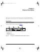
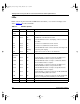
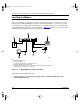
Table Of Contents
Getting Started Using FirstGear for the Model XM128S ISDN Digital Modem
Installation 3-3
2.
Connect the other end (female end) of the 25-pin straight cable to the serial (COM) port
on your computer.
3.
Using the ISDN cable that is included, connect the RJ-45 connector on one end of the
cable to the ISDN-S port on the back of the Model XM128S modem.
4.
Connect the other end of the ISDN cable to the S/T interface on your NT1 device.
5.
Using the proper cable, connect the NT1 device to the wall outlet installed by your phone
company.
6.
Insert the round end of the power adapter in the POWER connector on the rear panel.
7.
Plug the power adapter into an AC wall outlet.
8.
Turn the power on to your Model XM128S modem.
9.
Turn the power on to your computer.
Verifying Hardware Installation
When the installation is complete and power applied to the modem, a self-test sequence begins.
The B1, B2, and AA LED lights blink on and then off again. After this cycle is complete, the PWR
(power) LED remains on.
If the test routine fails, the D LED blinks. Refer to
Reference Guide for the Model XM128 ISDN
Digital Modem
for more information about the self-test and the error codes.
Installing Software for Windows
This section contains information about installing the Windows 95 and Windows NT
®
drivers and
about configuring Dial-Up Networking.
Note:
If your computer has a 9-pin serial connector, use a 25-pin to 9-pin converter
(25-pin male to 9-pin female). If you have a Macintosh, a special cable is needed for the
connection.
XM128S_bk.fm.book Page 3 Friday, March 6, 1998 11:33 AM