
User manual
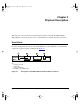
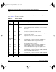
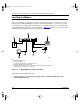
Table Of Contents
Getting Started Using FirstGear for the Model XM128S ISDN Digital Modem
Physical Description 2-3
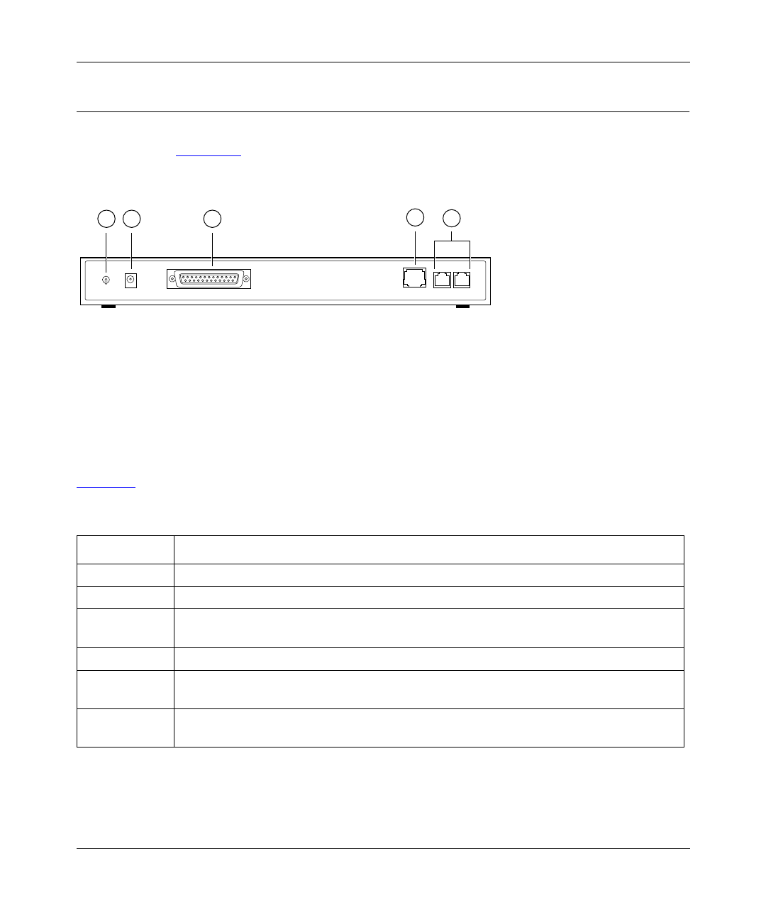
Rear Panel
The rear panel (Figure 2-2) contains a power switch; a power receptacle; and ports to connect a
computer, an ISDN line, and two analog devices (telephone, fax, or modem).
Key:
1 = ON/OFF switch
2 = Receptacle for power adapter
3 = RS-232 communication (COM) port for connecting to a computer
4 = ISDN-S port for connecting to an ISDN line
5 = PHONE 1 and PHONE 2 ports for connecting analog devices (telephone, fax, or modem)
Figure 2-2. Rear panel of the Model XM128S modem
Table 2-2 describes the components on the rear panel of the Model XM128S modem.
Table 2-2. Rear panel components
Label Description
ON/OFF This switch turns power on or off.
POWER This receptacle is for the power adapter.
RS-232 This RS-232 COM port is for connecting the Model XM128S modem to the serial port of a
computer or data terminal.
ISDN-S This port is for connecting the Model XM128S modem to the NT1 device.
PHONE 1 This port is for connecting the Model XM128S modem to an analog device (telephone,
fax, or modem).
PHONE 2 This port is for connecting the Model XM128S modem to an analog device (telephone,
fax, or modem).
7861MEA
RS-232
POWER
ON/OFF
1 2 3
ISDN-S
PHONE 1 PHONE 2
5
4
XM128S_bk.fm.book Page 3 Friday, March 6, 1998 11:33 AM