
User manual
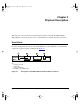
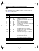
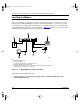
Table Of Contents
Physical Description 2-1
Chapter 2
Physical Description
This chapter provides information about the hardware features of the Model XM128S ISDN
Digital Modem. Use the key at the bottom of each illustration to identify the panel components.
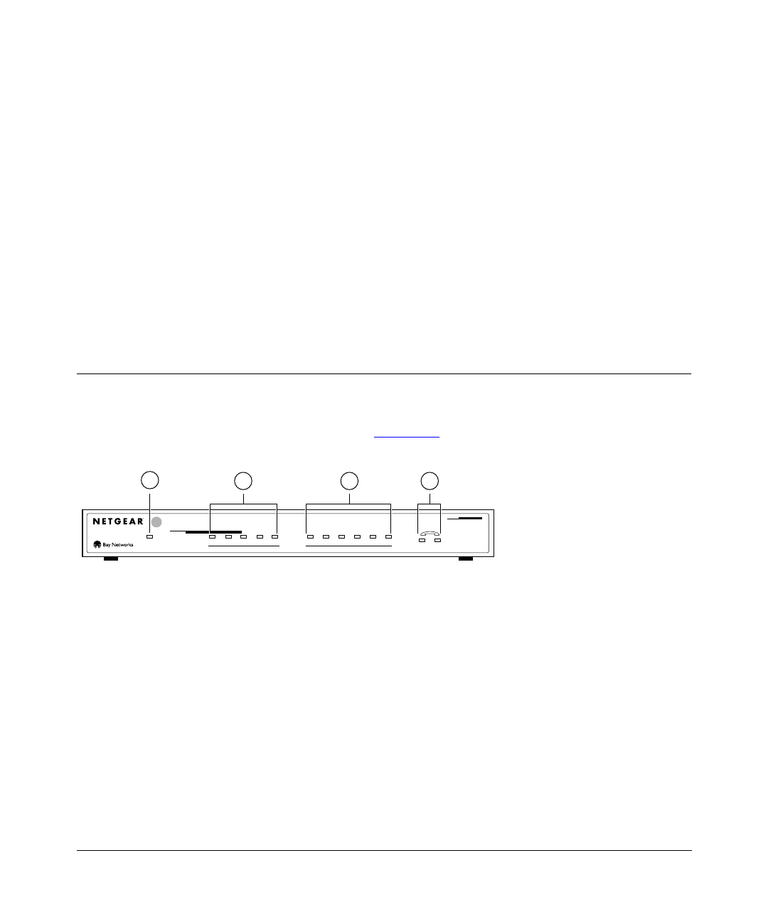
Front Panel
For easier management and control of the Model XM128S modem, familiarize yourself with the
components on the front panel, as illustrated in Figure 2-1.
Key:
1 = PWR (power) LED
2 = ISDN LEDs
3 = RS-232 COM LEDs
4 = PHONE 1 and PHONE 2 LEDs
Figure 2-1. Front panel of the Model XM128S modem (with S/T interface)
7848MEA
DTR DSR RTS CTS TDDPWR B1 B2 AA CP
ISDN
RD
12
ISDN Digital Modem
INTERFACE
128Kpbs
MODEL
XM128
S
COM
2 3 4
1
XM128S_bk.fm.book Page 1 Friday, March 6, 1998 11:33 AM