
Data Sheet


Target Application
1
2
3
NETG EAR
ProSAFE
M6100-3S
XCM8924X
Reset
SFP SP D/ Link /A CT Mo de: Green = Li nk at 10G Y el low = Lin k at 1G
Blink = ACT
Green =
Link at 10G
Yellow=
USB
OOB
Console
100M/1G
Blink=ACT
Supervisor
PWR/
Status
1F
2F
1T
2T
3F
4F
3T
4T
5F
6F
5T
6T
7F
8F
7T
8T
9F
10F
9T
10T
11F
12F
11T
12T
13F
14F
13T
14T
15F
16F
15T
16T
RJ45 SP D/ Link /A CT Mode: Gree n = Link at 10G Yellow = Li nk at 100M/1G Blink = ACT
23
24
21
22
19
20
17
18
Link at
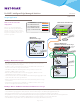
M4200 Series:
Wireless Access Layer
M6100 Series: Redundant Core
WIRING CLOSET – BUILDING 1
Fiber, 10GBASE-LR LITE single mode
Fiber, 10GBASE-LRM multimode
Copper, 1/ 2.5/ 5G PoE+ RJ45 Cat5e
Copper, 10GBASE-T RJ45 Cat6A
Fiber, 10GBASE-SR multimode
Wireless APs
WAREHOUSE – BUILDING 2
M4300 and M4200 Series:
Distribution and Wireless Access Layer
P
RO
S
AFE
Power
Reset
Fan
Stack ID
RJ45 LED: Green=10G, Yellow=100M/1G, Blink=ACT
14
13
16
15
18
17
20
19
22
21
24
23
M4300-12X12F
2
1
4
3
6
5
8
7
10
9
12
11
Stack
Master
Console (USB)
115200, N, 8, 1
USB
SFP+ LED: Green=10G, Yellow=1G, Blink=ACT
P
RO
S
AFE
Power
Reset
Fan
Stack ID
RJ45 LED: Green=10G, Yellow=100M/1G, Blink=ACT
14
13
16
15
18
17
20
19
22
21
24
23
M4300-12X12F
2
1
4
3
6
5
8
7
10
9
12
11
Stack
Master
Console (USB)
115200, N, 8, 1
USB
SFP+ LED: Green=10G, Yellow=1G, Blink=ACT
M4300-12X12F
M4300-12X12F
L2/L3/L4 LACP
P
RO
S
AFE
Power
Reset
Console (USB)
115200, N, 8, 1
USB
Link/AC Mode:
Console
OOB
SPD ACT
Green=1G
Yellow=10/100M
115200,N,8,1
Fan
Green=10G, Yellow=1G, Blink=ACT
3 4 5 6 7 8 9 10
1
2
M4200-10MG-PoE+
100-240~50-60Hz, 5A max.
RJ45 SPD Mode:
Yellow=10/100M
Green=2.5G,
Blink=ACT
PoE Mode:
Green=PoE Powered
Yellow=PoE Fault
Off=no PD
RJ45 SPD Mode:
Yellow=10/100M
Green=2.5G,
Blink=ACT
PoE Mode:
Green=PoE Powered
Yellow=PoE Fault
Off=no PD
SPD PoE
M4200-10MG-PoE+
P
RO
S
AFE
Power
Reset
Console (USB)
115200, N, 8, 1
USB
Link/AC Mode:
Console
OOB
SPD ACT
Green=1G
Yellow=10/100M
115200,N,8,1
Fan
Green=10G, Yellow=1G, Blink=ACT
3 4 5 6 7 8 9 10
1
2
M4200-10MG-PoE+
100-240~50-60Hz, 5A max.
RJ45 SPD Mode:
Yellow=10/100M
Green=2.5G,
Blink=ACT
PoE Mode:
Green=PoE Powered
Yellow=PoE Fault
Off=no PD
RJ45 SPD Mode:
Yellow=10/100M
Green=2.5G,
Blink=ACT
PoE Mode:
Green=PoE Powered
Yellow=PoE Fault
Off=no PD
SPD PoE
2.4
GHz GHz
5
2.4
GHz GHz
5
2.4
GHz GHz
5
M4200-10MG-PoE+
P
RO
S
AFE
Power
Reset
Console (USB)
115200, N, 8, 1
USB
Link/AC Mode:
Console
OOB
SPD ACT
Green=1G
Yellow=10/100M
115200,N,8,1
Fan
Green=10G, Yellow=1G, Blink=ACT
3 4 5 6 7 8 9 10
1
2
M4200-10MG-PoE+
100-240~50-60Hz, 5A max.
RJ45 SPD Mode:
Yellow=10/100M
Green=2.5G,
Blink=ACT
PoE Mode:
Green=PoE Powered
Yellow=PoE Fault
Off=no PD
RJ45 SPD Mode:
Yellow=10/100M
Green=2.5G,
Blink=ACT
PoE Mode:
Green=PoE Powered
Yellow=PoE Fault
Off=no PD
SPD PoE
2.4
GHz GHz
5
2.4
GHz GHz
5
2.4
GHz GHz
5
2.4
GHz GHz
5
2.4
GHz GHz
5
2.4
GHz GHz
5
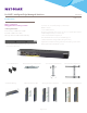
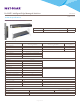
M4200-10MG-PoE+
Wave 2 11ac Access Point
deployment
M4200 is the world’s first Multigigabit
Ethernet switch with eight full power PoE+
and multi-speed 1G, 2.5G ports combined
with two 10G uplinks for a fully non-blocking
deployment of eight Wave 2 11ac access
points from any vendor.
.
Building 1: Wireless Access Layer
•With Wave 2 802.11ac, wired networks need to expand their reach and scope to
support speeds greater than 1 Gigabit
•In addition, power-constrained environments can benefit from full power PoE+ to
support access points in a range of environments
•The M4200-10MG-PoE+ was designed from the ground up to optimize the
installation of Wave 2 11ac access points
•With 8 x 2.5G to the APs and 2 x 10G line rate aggregation, M4200 connects
redundantly directly to a M6100 core chassis
•The two SFP+ uplinks connect to two dierent 10G blades using link aggregation (L2/
L3/L4 LACP) with load-balancing and failover
•M6100 management unit hitless failover and nonstop forwarding ensure no single
point of failure
•Using LACP in aggregation to this redundant core, M4200 allows for wire-speed
wireless access layer, with PoE+ full provisioning
Building 2: M4300 and M4200 Distribution and Wireless Access Layer
•In this warehouse, two half-width M4300 10GbE models are paired in a single rack space for redundant distribution layer
•Compared with a single aggregation switch, such two-unit horizontal stacking is cost-eective yet highly ecient for HA
•Management unit hitless failover and nonstop forwarding ensures no single point of failure for M4200 access switches
•Every M4200 can connect to both redundant distribution switches using link aggregation (L2/L3/L4 LACP) with load-balancing and failover
•When too far from the wiring closet, M4200 distant switches are securely mounted on poles across the warehouse
•This redundant topology allows for wire-speed 8x2.5G wireless access layer, with PoE+ full provisioning
ProSAFE® Intelligent Edge Managed Switches Data Sheet
M4200 series
Page 11 of 31