
User Manual
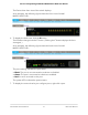
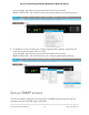

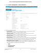

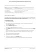
Table Of Contents
- Contents
- 1. Get Started with the Main UI
- 2. Configure Switch System Information
- Switch system information
- Loopback interface
- IPv4 management interfaces and VLANs
- IPv6 management interfaces and VLANs
- Configure an IPv6 service port
- Manage IPv6 addresses for the IPv6 service port
- Configure an IPv6 management VLAN
- Manage IPv6 addresses for the IPv6 management VLAN
- Manage the IPv6 default route addresses for the IPv6 management VLAN
- Configure an IPv6 management interface
- Manage IPv6 addresses for the IPv6 management interface
- Manage the IPv6 default route addresses for the IPv6 management interface
- Time and SNTP settings
- Precision Time Protocol
- Domain Name System
- Switch database management template
- Green Ethernet settings
- Configure the global green Ethernet settings
- Configure green Ethernet interface settings
- Configure and display detailed green Ethernet settings for an interface
- Display green Ethernet information for the link partner of an interface
- Display the green Ethernet statistics summary
- Configure and display the green Ethernet EEE LPI history for an interface
- Bonjour settings
- IPv4 DHCP server
- DHCP relay and relay statistics
- DHCP Layer 2 relay
- UDP relay
- DHCPv6 server
- DHCPv6 relay interface
- Power over Ethernet
- Timer schedules
- Simple Network Management Protocol
- Link Layer Discovery Protocol
- Link Layer Discovery Protocol for Media Endpoint Devices
- Link dependency
- Industry Standard Discovery Protocol
- 3. Configure Switching Information
- VLANs
- Manage the VLAN configuration on the switch
- Auto-Trunk overview
- Enable or disable Auto-Trunks
- Configure the switch port mode settings for interfaces
- Configure membership interfaces for a VLAN
- View the VLAN status on the switch
- Change the port VLAN ID settings
- Configure a MAC-based VLAN
- Configure a protocol-based VLAN group
- Configure membership interfaces for a protocol-based VLAN group
- Configure an IP subnet-based VLAN
- Configure a double VLAN
- Configure a voice VLAN
- Configure Generic Attribute Registration Protocol
- Auto-VoIP
- Spanning Tree Protocol
- Configure the STP settings and display the STP status
- Configure the CST settings and display the CST status
- Configure the CST interface settings
- Display the CST interface Status
- Manage MST instances
- Configure and display the interface settings for an MST instance
- Display the STP interface statistics
- Configure the PVST/RPVST VLAN settings
- Change a PVST/RPVST VLAN configuration
- Remove a PVST/RPVST VLAN configuration
- Configure the PVST and RPVST interface settings
- Display the PVST and RPVST statistics
- Multicast forwarding database
- Internet Group Management Protocol snooping
- Configure IGMP snooping automatically with IGMP Plus mode
- Configure IGMP snooping manually
- Configure the IGMP snooping settings for interfaces
- Configure IGMP snooping for VLANs automatically with IGMP Plus mode
- Configure IGMP snooping for VLANs manually
- Configure an IGMP multicast router interface
- Configure an IGMP multicast router VLAN
- IGMP snooping querier overview
- Configure the IGMP snooping querier global settings
- Configure an IGMP snooping querier for a VLAN
- Remove the IGMP snooping querier settings for a VLAN
- Display the status of the IGMP snooping querier
- Multicast Listener Discovery snooping
- Configure MLD snooping automatically with MLD Plus mode
- Configure MLD snooping manually
- Configure the MLD snooping settings for interfaces
- Configure MLD snooping for VLANs automatically with MLD Plus mode
- Configure MLD snooping for VLANs manually
- Remove the MLD snooping querier settings for a VLAN
- Configure an MLD multicast router interface
- Configure an MLD multicast router VLAN
- Configure the MLD snooping querier global settings
- Configure an MLD snooping querier for a VLAN
- Remove the MLD snooping querier settings for a VLAN
- Multicast VLAN registration
- MAC address table
- Port settings
- Link aggregation groups
- 802.1AS timing and synchronization
- Multiple Registration Protocol settings
- Loop protection
- VLANs
- 4. Manage Routing
- Routing concepts
- Routing table, routes and route preferences
- IPv4 routing
- IPv6 routing
- Manage the global IPv6 routing settings
- Display the IPv6 route table
- Configure IPv6 routing interfaces
- Configure prefix settings for an IPv6 routing interface
- Delete a prefix setting from an IPv6 routing interface
- Display the IPv6 and ICMPv6 statistics for an IPv6 routing interface
- Display the IPv6 neighbor table or clear IPv6 neighbor entries
- Configure IPv6 static routes
- Delete an IPv6 static route
- Configure the IPv6 route preference for the switch
- Configure IPv6 tunnels
- Delete an IPv6 tunnel
- Routing VLANs
- Address Resolution Protocol
- Routing Information Protocol
- Router discovery and router advertisements
- 5. Configure Multicast Routing
- IPv4 multicast routing and the IPv4 multicast route table
- IGMP for IPv4 multicast routing
- Configure the global IGMP settings for the switch
- Configure an IGMP routing interface
- Display the statistics for the IGMP routing interfaces
- Display the IGMP groups and search the IGMP group database
- Display the IGMP membership information and search the IGMP membership database
- Configure an IGMP proxy interface
- Display the statistics for the IGMP proxy interface
- Display the IGMP proxy membership and search the IGMP proxy membership database
- PIM for IPv4 multicast routing
- Configure the global PIM IPv4 settings on the switch
- Add IPv4 PIM-SSM groups
- Delete an IPv4 PIM-SSM group
- Configure an IPv4 PIM interface
- Display IPv4 PIM neighbors and search the PIM neighbor database
- Add an IPv4 PIM candidate rendezvous point configuration
- Delete an IPv4 PIM candidate rendezvous point configuration
- Configure an interface as an IPv4 PIM bootstrap router candidate
- Delete an IPv4 PIM bootstrap router candidate configuration
- Configure a static IPv4 PIM rendezvous point for a group
- Delete a static IPv4 PIM rendezvous point configuration
- Static multicast routes for IPv4 addresses
- Multicast admin boundaries for IPv4 addresses
- IPv6 multicast routing and the IPv6 multicast route table
- PIM for IPv6 multicast routing
- Configure the global PIM IPv6 settings on the switch
- Add IPv6 PIM-SSM groups
- Delete an IPv6 PIM-SSM group
- Configure an IPv6 PIM interface
- Display IPv6 PIM neighbors and search the PIM neighbor database
- Add an IPv6 PIM candidate rendezvous point configuration
- Delete an IPv6 PIM candidate rendezvous point configuration
- Configure an interface as an IPv6 PIM bootstrap router candidate
- Delete an IPv6 PIM bootstrap router candidate configuration
- Configure a static IPv6 PIM rendezvous point for a group
- Delete a static IPv6 PIM rendezvous point configuration
- MLD for IPv6 multicast routing
- Configure the global MLP settings for the switch
- Configure an MLD routing interface
- Display the statistics for the MLD routing interfaces
- Display the MLD groups and search the MLD group database
- Display or clear MLD traffic statistics
- Configure an MLD proxy interface
- Display the statistics for the MLD proxy interface
- Display the MLD proxy membership and search the MLD proxy membership database
- Static multicast routes for IPv6 addresses
- 6. Configure Quality of Service
- Quality of Service concepts
- Class of Service
- CoS configuration concepts
- Configure the CoS trust mode settings globally or for a specific interface
- Map 802.1p priorities to queues
- Map DSCP values to queues
- Configure the CoS interface settings for an interface
- Configure CoS queue settings for an interface
- Configure the CoS WRED precedence settings for dropping packets
- Differentiated Services
- Defining DiffServ
- DiffServ wizard overview
- Use the DiffServ wizard to create a traffic class and policy for one or more interfaces
- Configure the DiffServ mode and display the entries in the DiffServ private MIB tables
- Configure a DiffServ class
- Configure an IPv6 DiffServ class
- Configure a DiffServ policy
- Configure the DiffServ service interface
- Display DiffServ service statistics
- 7. Manage Switch Security
- User accounts and passwords
- RADIUS servers
- TACACS+ servers
- Authentication lists
- Current login sessions
- HHTP and HTTPS management access
- SSH management access
- Telnet management access
- Console port management access
- Denial of service
- Management access profiles and rules
- Port authentication
- MAC filters for traffic control
- Port security
- Private port groups
- Protect ports
- Private VLANs
- Overview of the tasks for private VLAN configuration
- Assign a private VLAN type to a VLAN
- Configure a private VLAN association with a primary and secondary VLAN
- Remove an existing private VLAN association
- Configure the private VLAN port mode
- Private VLAN host interface: Assign the interface to primary and secondary VLANs
- Private VLAN host interface: Remove the interface from primary and secondary VLANs
- Private VLAN promiscuous interface: Assign the interface to primary and secondary VLANs
- Private VLAN promiscuous interface: Remove the interface from primary and secondary VLANs
- Private VLAN promiscuous trunk interface: Add primary and secondary VLANs to the trunk
- Private VLAN promiscuous trunk interface: Remove primary and secondary VLANs from the trunk
- Private VLAN isolated trunk interface: Add primary and secondary VLANs to the trunk
- Private VLAN isolated trunk interface: Remove primary and secondary VLANs from the trunk
- Configure native and allowed VLANs on a private VLAN trunk interface
- Storm control
- DHCP snooping
- DHCPv6 snooping
- IP source guard interfaces
- IPv6 source guard interfaces
- Dynamic ARP inspection
- Captive portals
- Configure the global captive portal settings
- Configure a captive portal
- Delete a captive portal
- Configure a captive portal binding
- Display or delete captive portal bindings in the captive portal binding table
- Configure captive portal groups
- Configure captive portal users
- Configure the captive portal trap flag settings
- Display or clear captive portal client statistics
- Access control lists
- Use the ACL Wizard to create a simple ACL
- Configure a MAC ACL
- Configure MAC ACL rules
- Configure MAC bindings
- Display or delete MAC ACL bindings in the MAC binding table
- Configure a basic or extended IPv4 ACL
- Configure rules for a basic IP ACL
- Configure rules for an extended IPv4 ACL
- Configure an IPv6 ACL
- Configure rules for an IPv6 ACL
- Configure IP ACL interface bindings
- Display or delete IP ACL bindings in the IP ACL binding table
- Configure VLAN ACL bindings
- 8. Monitor the Switch and Network
- 9. Maintenance and Troubleshooting
- A. Configuration Examples
- B. Software Default Settings and Hardware Specifications
- Access default settings for the switch device UI
- System features default settings
- Switching features default settings
- Routing and multicast features default settings
- QoS features default settings
- Security features default settings
- Monitoring features default settings
- Model-specific hardware technical specifications
- Model M4250-10G2F-PoE+ (SKU GSM4212P)
- Model M4250-10G2XF-PoE+ (SKU GSM4212PX)
- M4250-10G2XF-PoE++ (SKU GSM4212UX)
- M4250-26G4F-PoE+ (SKU GSM4230P)
- M4250-26G4XF-PoE+ (SKU GSM4230PX)
- M4250-26G4F-PoE++ (SKU GSM4230UP)
- M4250-40G8F-PoE+ (SKU GSM4248P)
- M4250-40G8XF-PoE+ (SKU GSM4248PX)
- M4250-40G8XF-PoE++ (SKU GSM4248UX)
- M4250-12M2XF (SKU MSM4214X)
- M4250-16XF (SKU XSM4216F)
- General hardware technical specifications

The Device View front view of the switch displays.
As an example, the following figure shows the front view of model
M4250-10G2F-PoE+.
6. To display the back view, click the B button.
The B button changes into the F button. (Clicking the F button displays the front
view again.)
As an example, the following figure shows the back view of model
M4250-10G2F-PoE+.
The port coloring indicates the port status:
• Black. The port is not connected to a device or disabled.
• Green. The port is connected to a device or enabled.
• Red. An error occurred on the port.
The system LEDs indicate the system status:
7.
To display the menus that let you configure ports, right-click a port.
Main User Manual31Get Started with the Main UI
AV Line of Fully Managed Switches M4250 Series Main User Manual