
System information


Appendix B: Configuration Examples | 307
GS752TXS Smart Switch Software Administration Manual
kind outside the Region, in other words connectivity within the region is independent of
external connectivity.
MSTP Example Configuration
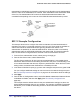
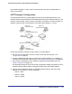
This example shows how to create an MSTP instance from the GS752TXS switch. The
example network has three different GS752TXS switches that serve different locations in the
network. In this example, ports g1–g5 are connected to host stations, so those links are not
subject to network loops. Ports g6–g8 are connected across switches 1, 2, and 3.
Ports g1-g5
Switch 1
Connected to Hosts
Root Bridge
Switch 2
Switch 3
Ports g1-g5
Connected to Hosts
Ports g1-g5
Connected to Hosts
Ports g6-g8
Connected to Switch 2 and 3
Ports g6-g8
Connected to Switch 1 and 2
Perform the following procedures on each switch to configure MSTP:
1. Use the VLAN Configuration screen to create VLANs 300 and 500 (see VLAN
Configuration on page 97).
2. Use the VLAN Membership screen to include ports g1–g8 as tagged (T) or untagged (U)
members of VLAN 300 and VLAN 500 (see VLAN Membership Configuration on page 98).
3. From the STP Configuration screen, enable the Spanning Tree State option (see STP
Switch Configuration on page 110).
Use the default values for the rest of the STP configuration settings. By default, the STP
Operation Mode is MSTP and the Configuration Name is the switch MAC address.
4. From the CST Configuration screen, set the Bridge Priority value for each of the three
switches to force Switch 1 to be the root bridge:
• Switch 1: 4096
• Switch 2: 12288
• Switch 3: 20480