
Quick Start Manual


Power connector
Kensington Lock™ slot
12
GS728TXS/GS752TXS Smart Switch
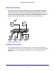
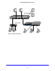
Figure 3. GS728TXS back panel
The back panel contains a power connector.
LED Designations
This section describes the LEDs on the smart switch.
Port LEDs
The following table describes the RJ-45 and dedicated SFP port LED designations. Each
RJ-45 port has one LED.
Table 1. Port LEDs
LED Designation
Link/Speed/ACT LED mode for
copper ports 1 to 24
• Off. No link is established.
• So
lid green . A valid 1000-Mbps link is established.
• Blinking green . The port is transmitting or receiving packets at
1000 Mbps.
• So
lid yellow . A valid 10/100-Mbps link is established.
• Blinking y
ellow . The port is transmitting or receiving packets
at 10/100 Mbps.
Link/ACT LED for SFP+ ports
25 to 28
• Off . No SFP+ module link is established.
• So
lid green . A valid 10-Gbps link is established.
• Blin
king green . The port is transmitting or receiving packets
at 10 Gbps.
• So
lid yellow . A valid 1000-Mbps link is established.
• Blinking y
ellow . The port is transmitting or receiving packets at
1000 Mbps.
Each SFP port has its own LED.