GS728TXS/GS752TXS Smart Switch Hardwa re Installation Guide 350 East Plumeria Drive San Jose, CA 95134 USA March 2013 202-11201-01 v1.
GS728TXS/GS752TXS Smart Switch Support Thank you for selecting NETGEAR products. After installing your device, locate the serial number on the label of your product and use it to register your product at https://my.netgear.com. You must register your product before you can use NETGEAR telephone support. NETGEAR recommends registering your product through the NETGEAR website. For product updates and web support, visit http://support.netgear.com Phone (US & Canada only): 1-888-NETGEAR.
Contents Chapter 1 Introduction Overview . . . . . . . . . . . . . . . . . . . . . . . . . . . . . . . . . . . . . . . . . . . . . . . . . . . Features . . . . . . . . . . . . . . . . . . . . . . . . . . . . . . . . . . . . . . . . . . . . . . . . . . . Stacking. . . . . . . . . . . . . . . . . . . . . . . . . . . . . . . . . . . . . . . . . . . . . . . . . . . . Package Contents . . . . . . . . . . . . . . . . . . . . . . . . . . . . . . . . . . . . . . . . . . . .
GS728TXS/GS752TXS Smart Switch Configuration . . . . . . . . . . . . . . . . . . . . . . . . . . . . . . . . . . . . . . . . . . . . . 30 Switch Integrity . . . . . . . . . . . . . . . . . . . . . . . . . . . . . . . . . . . . . . . . . . . . 30 Autonegotiation. . . . . . . . . . . . . . . . . . . . . . . . . . . . . . . . . . . . . . . . . . . . 30 Appendix B Technical Specifications Network Protocol and Standards Compatibility . . . . . . . . . . . . . . . . . . . . . 32 Management . . . . . . . . . . .
1. 1 Introduction Congratulations on the purchase of your NETGEAR® ProSafeTM GS728TXS/GS752TXS Smart Switch! Your GS728TX/GS752TXS Smart Switch is a state-of-the-art, high-performance, IEEE-compliant network solution designed for users who require many ports and want the power of Gigabit connectivity to eliminate bottlenecks, boost performance, and increase productivity.
GS728TXS/GS752TXS Smart Switch Overview The NETGEAR GS728TXS/GS752TXS Smart Switch provides either 24 (GS728TXS) or 48 (GS752TXS) twisted-pair ports that support nonstop 10/100/1000M networks. The switch also has four built-in enhanced small form factor pluggable (SFP+) GBIC slots that support 1000M and 10G optical modules or up to two stacking modules. Using these Gigabit slots, you can create high-speed connections to a server or network backbone.
GS728TXS/GS752TXS Smart Switch - IEEE 802.3z (1000BASE-x) - IEEE 802.3 Clause 49 (10GBASE-LR and 10GBASE-SR) - IEEE802.aq (10GBASE-LRM) - IEEE802.3ae (10GBASE Ethernet) - IEEE802.3az (Energy Efficient Ethernet) - IEEE 802.3x (Full-duplex flow control) • AutoSensing and autonegotiating capabilities for all ports. • Auto Uplink™ on all ports to make the right connection. • Automatic address learning function to build the packet-forwarding information table.
GS728TXS/GS752TXS Smart Switch Switch software is downloaded separately for each stack member. However, all units in the stack must be running the same software version. A stack unit can operate in one of the following modes: • A standalone unit runs as a general switch. The standalone unit does not run the stacking application until it is connected to a stack. • The master unit manages the entire stack, and is responsible for the entire stack configuration.
GS728TXS/GS752TXS Smart Switch Verify that the package contains the following: • GS728TXS/GS752TXS Smart Switch • Rubber footpads for tabletop installation • Rack-mounting kits • Power cord • Installation guide • Smart switch resource CD with NETGEAR Smart Control Center and user’s manual If any item is missing or damaged, contact the place of purchase immediately.
2. 2 Physical Description This chapter describes the GS728TXS/GS752TXS Smart Switch hardware features.
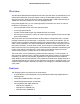
GS728TXS/GS752TXS Smart Switch GS728TXS Description This section describes the smart switch hardware features. GS728TXS Front Panel and Back Panel Configuration The GS728TXS has 24 10/100/1000-Mbps copper ports and 4 dedicated 1000 Mbps/10 Gbps SFP+ fiber ports. Up to 2 fiber ports (port 27 and 28) at a time can be used as stacking ports. Each port is capable of sensing the line speed and negotiating the duplex mode with the link partner automatically.
GS728TXS/GS752TXS Smart Switch Power connector Kensington Lock™ slot Figure 3. GS728TXS back panel The back panel contains a power connector. LED Designations This section describes the LEDs on the smart switch. Port LEDs The following table describes the RJ-45 and dedicated SFP port LED designations. Each RJ-45 port has one LED. Each SFP port has its own LED. Table 1.
GS728TXS/GS752TXS Smart Switch System LEDs The following table describes the system LED designations. Table 2. System LEDs LED Designation Power • • • Solid green . The device is powered on; runtime code is operating. Solid yellow. The device is booting up. Off . Power is not supplied to the device. Fan • • Solid yellow. The fan has failed. Off . The fan is operating normally. Stack Master LED • Solid green . The switch acts as a master unit in a stack of GS7XXTXS series switches. Off .
GS728TXS/GS752TXS Smart Switch SFP+ Ports To enable you to have fiber connections on your network, four SFP+ ports (25 through 28) accommodate standard 1000M and 10G SFP+ transceiver modules, which are sold separately. The SFP+ ports can alternatively be used to connect the switch to a stack. Up to two ports (ports 27 and 28) can be used at a time as stacking ports. Reset Button The smart switch has a Reset button on the front panel to allow you to manually reboot the switch.
GS728TXS/GS752TXS Smart Switch Power, Fan, and Stack Master LEDs 1000M/10G SFP ports Link/Speed/ACT LEDs Stack ID LED GS752TXS Link/Act Mode — Power Stack Master Reset 1 2 3 4 5 6 7 8 9 10 11 12 13 14 15 16 17 18 19 20 21 22 23 24 25 26 27 28 29 30 31 32 33 34 35 36 37 38 39 40 41 42 43 44 45 46 47 48 49F 50F 51F 52F Green=Link at 1G Yellow=Link at 10/ 100M Fan SFP + ID Green=10G Link Yellow=1G Blink=ACT Factory Defaults Factory Defaults but
GS728TXS/GS752TXS Smart Switch Port LEDs The following table describes the RJ-45 and dedicated SFP port LED designations. Each RJ-45 port has one LED. Each SFP port has its own LED. Table 3. Port LEDs LED Designation Link/Speed/ACT LED mode for copper ports 1 to 48 • • • • • Link/ACT LED for SFP+ ports 49 to 52 • • • • • Off. No link is established. Solid green . A valid 1000-Mbps link is established. Blinking green . The port is transmitting or receiving packets at 1000 Mbps. Solid yellow.
GS728TXS/GS752TXS Smart Switch RJ-45 Ports RJ-45 ports are AutoSensing ports. When you insert a cable into an RJ-45 port, the switch automatically ascertains the maximum speed (10, 100, or 1000 Mbps) and duplex mode (half-duplex or full-duplex) of the attached device. All ports support only an unshielded twisted-pair (UTP) cable terminated with an 8-pin RJ-45 plug. To simplify the procedure for attaching devices, all RJ-45 ports support Auto Uplink.
3. 3 Applications Your GS728TXS/GS752TXS Smart Switch is designed to provide flexibility in configuring your network connections. It can be used as your only network traffic-distribution device or with 10 Mbps, 100 Mbps, 1000 Mbps, and 10-Gbps hubs and switches.
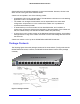
GS728TXS/GS752TXS Smart Switch Desktop Switching The smart switch can be used as a desktop switch to build a small network that enables users to have 1000-Mbps access to a file server. With full duplex enabled, the switch port connected to the server or computer can provide 2000 Mbps throughput. If a 10-Gbps module is used to connect the switch to the file server in full-duplex operation, then the server can provide up to 20 Gbps throughput.
GS728TXS/GS752TXS Smart Switch GS728TXS/GS752TXS GS752TXS Link/Act Mode — Power Stack Master Reset 1 2 3 4 5 6 7 8 9 10 11 12 13 14 15 16 17 18 19 20 21 22 23 24 25 26 27 28 29 30 31 32 33 34 35 36 37 38 39 40 41 42 43 44 45 46 47 48 50F 49F 52F 51F Green=Link at 1G Yellow=Link at 10/ 100M Fan SFP + ID Green=10G Link Yellow=1G Blink=ACT Factory Defaults Model FS728TP Model GS108T ` ` ` ` Figure 7.
4. 4 Installation This chapter describes the installation procedures for your GS728TXS/GS752TXS Smart Switch.
GS728TXS/GS752TXS Smart Switch Step 1: Prepare the Site Before you install the switch, ensure that the operating environment meets the site requirements in the following table. Table 5. Site requirements Characteristics Requirements Mounting • • Access Locate the switch in a position that allows you to access the front panel RJ-45 ports, view the front panel LEDs, and access the power connector. Power source Provide a power connection cord.
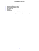
GS728TXS/GS752TXS Smart Switch Install the Switch in a Rack To install the switch in a rack, you need the 19-inch rack-mount kit supplied with the switch. To install the switch in a rack: 1. Attach the supplied mounting brackets to the side of the switch. 2. Insert the screws provided in the rack-mount kit through each bracket and into the bracket mounting holes in the switch. 3. Tighten the screws with a No. 1 Phillips screwdriver to secure each bracket. 4.
GS728TXS/GS752TXS Smart Switch GS752TXS Link/Act Mode — Power Stack Master Reset 1 2 3 4 5 6 7 8 9 10 11 12 13 14 15 16 17 18 19 20 21 22 23 24 25 26 27 28 29 30 31 32 33 34 35 36 38 37 39 40 41 42 43 44 45 46 47 48 49F 50F 51F 52F Green=Link at 1G Yellow=Link at 10/ 100M Fan SFP + ID Green=10G Link Yellow=1G Blink=ACT Factory Defaults ` ` Figure 8.
GS728TXS/GS752TXS Smart Switch GS752TXS Link/Act Mode — Power Stack Master Reset 1 2 3 4 5 6 7 8 9 10 11 12 13 14 15 16 17 18 19 20 21 22 23 24 25 26 27 28 29 30 31 32 33 34 35 36 37 38 39 40 41 42 43 44 45 46 47 48 49F 50F 51F 52F Green=Link at 1G Yellow=Link at 10/ 100M Fan SFP + ID Green=10G Gre Green Green= Gree Gr Green=1 G re ee een=1 een= en=1 =1 = 10 0G G Lin LLink Liin in nkk Y Yellow=1G ellow=1G B link=ACT Blink=ACT Factory Defaults Fi
GS728TXS/GS752TXS Smart Switch The device is Plug and Play in terms of stacking configuration. Before powering up the device, connect the devices into the required stacking topology. Then power up the devices. By default, the switch is configured to allow the master and slave designations to be determined through automatic discovery.
GS728TXS/GS752TXS Smart Switch Note: The switch is configured with a default IP address of 192.168.0.239 and a subnet mask of 255.255.255.0.
A. A Troubleshooting This appendix provides information about troubleshooting the NETGEAR smart switch.
GS728TXS/GS752TXS Smart Switch Troubleshooting Chart The following table lists symptoms, causes, and solutions of possible problems. Table 6. Troubleshooting chart Symptom Cause Solution Power LED is off. No power is received. Check the power cord connections and the connected device. Ensure that all cables used are correct and comply with Ethernet specifications. Link LED is off or blinking. Port connection is not working.
GS728TXS/GS752TXS Smart Switch Network Adapter Cards Ensure that the network adapter cards installed in the computers are in working condition and the software driver has been installed. Configuration If problems occur after you alter the network configuration, restore the original connections and determine the problem by implementing the new changes, one step at a time. Ensure that cable distances, repeater limits, and other physical aspects of the installation do not exceed the Ethernet limitations.
B. Technical Specifications B This appendix lists the specifications for the NETGEAR smart switch.
GS728TXS/GS752TXS Smart Switch Network Protocol and Standards Compatibility • IEEE 802.3 10BASE-T • IEEE 802.3u 100BASE-TX • IEEE 802.3ab 1000BASE-T • IEEE 802.3z 1000BASE-X • IEEE 802.3 Clause 49 (10GBASE-LR and 10GBASE-SR) • IEEE802.3aq (10GBASE-LRM) • IEEE802.3ae (10GBASE Ethernet) • IEEE 802.3x full-duplex flow control • IEEE802.3az (Energy Efficient Ethernet) Management • Windows 2000 + XP, Vista; Windows 7, Microsoft Explorer 8.0 or later; Firefox 3.0 or later • IEEE 802.
GS728TXS/GS752TXS Smart Switch Interface This section lists the interfaces specifications for the GS728TXS Smart Switch and the GS752TXS Smart Switch. GS728TXS Smart Switch • 24 RJ-45 connectors for 10BASE-T, 100BASE-TX, and 1000BASE-T (Auto Uplink on all ports). • Four 10 Gbps SFP+ slots (ports 25–29) to support 10-Gbps optical module and 1G optical module. Ports 28 and 29 can be used as stacking ports or as uplink ports.
GS728TXS/GS752TXS Smart Switch Physical Specifications • Dimensions (H x W x D): 43 mm x 440 mm x 257 mm (1.7 in. x 17.3 in. x10.1 in.) • Weight: - GS728TXS Smart Switch: 3.55 kg (7.83 lbs) - GS752TXS Smart Switch: 4.50 kg (9.
C. Notification of Compliance N ETGE A R Wire d P ro d uct s C Regulatory Compliance Information This section includes user requirements for operating this product in accordance with National laws for usage of radio spectrum and operation of radio devices. Failure of the end-user to comply with the applicable requirements may result in unlawful operation and adverse action against the end-user by the applicable National regulatory authority.
GS728TXS/GS752TXS Smart Switch FCC Guidelines for Human Exposure This equipment complies with FCC radiation exposure limits set forth for an uncontrolled environment. This equipment should be installed and operated with minimum distance of 20 cm between the radiator and your body. This transmitter must not be co-located or operating in conjunction with any other antenna or transmitter. FCC Declaration Of Conformity We, NETGEAR, Inc.