
User Manual
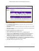

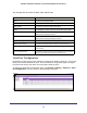
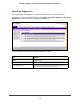
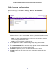
Table Of Contents
- GS728TS, GS728TPS, GS752TS, and GS752TPS Gigabit Smart Switches
- Contents
- 1. Getting Started
- Getting Started with the Smart Switches
- Switch Management Interface
- Connecting the Switch to the Network
- Switch Discovery in a Network with a DHCP Server
- Switch Discovery in a Network without a DHCP Server
- Configuring the Network Settings on the Administrative System
- Web Access
- Smart Control Center Utilities
- Understanding the User Interfaces
- Interface Naming Convention
- 2. Configuring System Information
- 3. Configuring Switching Information
- 4. Configuring Routing
- 5. Configuring Quality of Service
- 6. Managing Device Security
- 7. Monitoring the System
- 8. Maintaining the System
- 9. Accessing Help
- A. Hardware Specifications and Default Values
- B. Configuration Examples
- C. Notification of Compliance
- Index

65
GS728TS, GS728TPS, GS752TS, and GS752TPS Gigabit Smart Switches
To change the settings for an existing stack member:
1. Select the check box next to the stack member to configure.
2. If desired, specify a new unit ID for the stack member in the Change to Switch ID field. The
renumbering process causes the unit to reload.
3. Specify the switch type, priority, or management status from the available fields.
4. Click Apply to save the changes to the stack member.
Note: If you configured a new unit number for an existing stack member, you
are
asked to confirm the change. Click OK to continue or Cancel to retain the
original settings.
5. Click Delete to remove the selected unit from the stack.
6. Click Refresh to update the page with the latest information from the switch.
7. Click Cancel to cancel the configuration on the screen and reset the data on the screen to
the latest value of the switch.
The following table describes the Stack Configuration fields.
Field Description
Hardware Management
Preference
The hardware management preference of the switch. The hardware
management preference can be disabled or unassigned.
Standby Status Identifies the switch that is configured as the Standby Unit. The possible
values are:
• Cfg Standby - Indicates that the unit is configured as the Standby Unit. The
unit configured as the Standby switch becomes the stack manager if the
current manager fails.
• Opr Standby - Indicates that this unit is operating as the Standby Unit and
the configured Standby Unit is not part of the stack.
• None - The switch is not configured as the Standby Unit.
Switch Status Displays the status of the selected unit. The possible values are:
• OK
• Unsupported
• Code Mismatch
• Config Mismatch
• Not Present