
User Manual
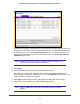
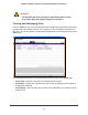
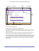
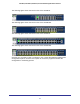
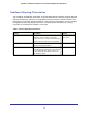
Table Of Contents
- GS728TS, GS728TPS, GS752TS, and GS752TPS Gigabit Smart Switches
- Contents
- 1. Getting Started
- Getting Started with the Smart Switches
- Switch Management Interface
- Connecting the Switch to the Network
- Switch Discovery in a Network with a DHCP Server
- Switch Discovery in a Network without a DHCP Server
- Configuring the Network Settings on the Administrative System
- Web Access
- Smart Control Center Utilities
- Understanding the User Interfaces
- Interface Naming Convention
- 2. Configuring System Information
- 3. Configuring Switching Information
- 4. Configuring Routing
- 5. Configuring Quality of Service
- 6. Managing Device Security
- 7. Monitoring the System
- 8. Maintaining the System
- 9. Accessing Help
- A. Hardware Specifications and Default Values
- B. Configuration Examples
- C. Notification of Compliance
- Index

30
GS728TS, GS728TPS, GS752TS, and GS752TPS Gigabit Smart Switches
Interface Naming Convention
The GS728TS, GS728TPS, GS752TS, and GS752TPS switches software supports physical
and logical interfaces. Interfaces are identified by their type and the interface number. The
physical ports are gigabit interfaces and are numbered on the front panel. You can configure
the logical interfaces by using the software. The following table describes the naming
convention for all interfaces available on the switch.
Table 2. Interface Naming Conventions
Interface Description Example
Physical The physical ports are gigabit Ethernet
interfaces and are numbered sequentially
starting from one. The number before the slash
indicates the unit number of the stack member.
1/g1, 1/g2, 1/g3
3/g21, 3/g22
Link Aggregation Group (LAG) LAG interfaces are logical interfaces that are
only used for bridging functions.
l1, l2, l3
CPU Management Interface This is the internal switch interface responsible
for the switch base MAC address. This interface
is not configurable and is always listed in the
MAC Address Table.
c1