
User Manual
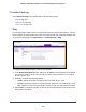
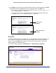

Table Of Contents
- GS728TS, GS728TPS, GS752TS, and GS752TPS Gigabit Smart Switches
- Contents
- 1. Getting Started
- Getting Started with the Smart Switches
- Switch Management Interface
- Connecting the Switch to the Network
- Switch Discovery in a Network with a DHCP Server
- Switch Discovery in a Network without a DHCP Server
- Configuring the Network Settings on the Administrative System
- Web Access
- Smart Control Center Utilities
- Understanding the User Interfaces
- Interface Naming Convention
- 2. Configuring System Information
- 3. Configuring Switching Information
- 4. Configuring Routing
- 5. Configuring Quality of Service
- 6. Managing Device Security
- 7. Monitoring the System
- 8. Maintaining the System
- 9. Accessing Help
- A. Hardware Specifications and Default Values
- B. Configuration Examples
- C. Notification of Compliance
- Index

295
GS728TS, GS728TPS, GS752TS, and GS752TPS Gigabit Smart Switches
To configure the Traceroute settings and send probe packets to discover the route to a host
on the network:
1. In the Hostname/IP Address field, specify the IP address or the hostname of the
station you want the switch to ping. The initial value is blank. This information is not
retained across a power cycle.
2. Optionally, configure the following settings:
• Probes Per Hop. Specify the number of times each hop should be probed. The valid
range is 1–10.
• MaxTTL. Specify the maximum time-to-live for a packet in number of hops. The valid
range is 1–255.
• InitTTL. Specify the initial time-to-live for a packet in number of hops. The valid range
is 1– 255.
• MaxFail. Specify the maximum number of failures allowed in the session. The valid
range is 0–255.
• Interval. Specify the time between probes in seconds. The valid range is 1–60.
• Port. Specify the UDP destination port in probe packets. The valid range is 1–65535.
• Size. Specify the size of probe packets. The valid range is 0–9192.
3. Click Cancel to cancel the operation on the screen and reset the data on the screen to the
latest value of the switch.
4. Click Apply to initiate the traceroute. The results display in the TraceRoute area.