
User Guide


Managing Device Security
209
GS716Tv3, GS724Tv4, and GS748Tv5 Smart Switches
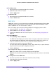
7. In the Binding Configuration area, specify the packet filtering direction for an ACL in the
Direction field.
Only the inbound direction is valid for the switches.
8. In the Port Selection Table area, select each port and LAG to which the ACL is applied.
In the following figure, the ACL rule is configured to check for packet matches on ports 8,
9, 13, and LAG 1. Packets that have a source address in the 192.168.3.0/24 network are
permitted to be forwarded by the interfaces. All other packets are dropped because every
ACL has an implicit deny all rule as the last rule.
9. Click the Add button.
Destination IPv6 L4
Port
• Destination L4 port (protocol). Specify the destination IPv6 L4 port
protocol.
• Destination L4 port (value). Specify the destination IPv6 L4 port
value.
Source IPv6 L4 Port
• Source L4 port (protocol). Specify the source IPv6 L4 port protocol.
• Source L4 port (value). Specify the source IPv6 L4 port value.
Table 67. ACL fields according to selected ACL type.
ACL Based On Fields