
User Manual
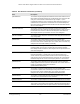
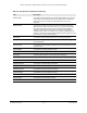
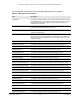
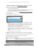
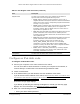
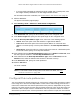
Table Of Contents
- 24-Port and 48-Port Gigabit Ethernet PoE+ Smart Switches with 4 SFP Ports
- Contents
- 1 Get Started
- Available publications
- Switch management options and default management mode
- Manage the switch by using the device UI
- About on-network and off-network access
- Access the switch on-network and connected to the Internet
- Use se a Windows-based computer to access the switch on-network and connected to the Internet
- Use the NETGEAR Insight mobile app to discover the IP address of the switch
- Use the NETGEAR Switch Discovery Tool to discover the switch when it is connected to the Internet
- Discover the switch in a network with a DHCP server using the Smart Control Center
- Use other options to discover the switch IP address
- Access the switch on-network when you know the switch IP address
- Access the switch off-network and not connected to the Internet
- Credentials for the device UI
- Register the switch
- Change the language of the device UI
- Change the management mode of the switch
- Use the Device View of the device UI
- Configure interface settings
- Access the NETGEAR support website
- Access the user manual online
- 2 Configure System Information
- View or define system information
- Configure the IP network settings for management access
- Configure the time settings
- Configure denial of service settings
- Configure DNS settings
- Configure green Ethernet settings
- Use the Device View
- Configure Power over Ethernet
- Configure SNMP
- Configure Link Layer Discovery Protocol
- Configure a DHCP L2 relay
- Configure DHCP snooping
- Configure Dynamic ARP Inspection
- Set up PoE timer schedules
- 3 Configure Switching
- Configure the port settings and maximum frame size
- Configure link aggregation groups
- Configure VLANs
- Configure a voice VLAN
- Configure Auto-VoIP
- Configure Spanning Tree Protocol
- Configure multicast
- Manage IGMP snooping
- Configure IGMP snooping
- Configure IGMP snooping for interfaces
- View, search, or clear the IGMP snooping table
- Configure IGMP snooping for VLANs
- Modify IGMP snooping settings for a VLAN
- Disable IGMP snooping on a VLAN and remove it from the table
- Configure one or more IGMP multicast router interfaces
- Configure an IGMP multicast router VLAN
- IGMP snooping querier overview
- Configure an IGMP snooping querier
- Configure an IGMP snooping querier for VLANs
- Display the status of the IGMP snooping querier for VLANs
- Manage MLD snooping
- Enable MLD snooping
- Configure MLD snooping for interfaces
- Configure the MLD VLAN settings
- Modify the MLD snooping settings for a VLAN
- Remove MLD snooping from a VLAN
- Configure one or more MLD multicast router interfaces
- Configure an MLD multicast router VLAN
- Configure an MLD snooping querier
- Configure the MLD snooping querier VLAN settings
- Configure multicast VLAN registration
- View, search, and manage the MAC address table
- Configure Layer 2 loop protection
- 4 Configure Routing
- 5 Configure Quality of Service
- 6 Manage Device Security
- Change the device admin password for the device UI
- Manage the RADIUS settings
- Configure the TACACS+ settings
- Configure authentication lists
- Manage the Smart Control Center
- Configure management access
- Control access with profiles and rules
- Configure port authentication
- Set up traffic control
- Configure access control lists
- Use the ACL Wizard to create a simple ACL
- Configure a MAC ACL
- Configure MAC ACL rules
- Configure MAC bindings
- View or delete MAC ACL bindings in the MAC binding table
- Configure a basic or extended IPv4 ACL
- Configure rules for a basic IPv4 ACL
- Configure rules for an extended IPv4 ACL
- Configure an IPv6 ACL
- Configure rules for an IPv6 ACL
- Configure IP ACL interface bindings
- View or delete IP ACL bindings in the IP ACL binding table
- Configure VLAN ACL bindings
- 7 Monitor the Switch and the Traffic
- 8 Maintain or Troubleshoot the switch
- A Configuration Examples
- B Specifications and Default Settings

24-Port and 48-Port Gigabit Ethernet PoE+ Smart Switches with 4 SFP Ports
Configure Routing User Manual277
Configure an IPv6 static route
To configure an IPv6 static route:
1. Connect your computer to the same network as the switch.
You can use a WiFi or wired connection to connect your computer to the network, or
connect directly to a switch that is of
f-network using an Ethernet cable.
2. Launch a web browser.
3. In the address field of your web browser
, enter the IP address of the switch.
If you do not know the IP address of the switch, see
Access the switch on-network and
connected to the Internet on page 21 or Access the switch off-network and not
connected to the Internet on page 29.
The Device UI login page displays.
If you did not yet activate your warranty, the Register to activate your warranty page
displays. For more information, see
Register the switch on page 32.
4. Enter one of the following passwords:
• Enter your device admin password.
Neighbor State The state of the neighbor cache entry. Following are the states for
dynamic entries in the IPv6 neighbor discovery cache:
• Incmp.
Address resolution is being performed on the entry. A
neighbor solicitation message was sent to the solicited-node multicast
address of the target, but the corresponding neighbor advertisement
message is not yet received.
• Reach. Positive confirmation was received within the last Reachable
Time milliseconds that the forward path to the neighbor was
functioning properly. While in REACH state, the device takes no
special action as packets are sent.
• Stale. More than Reachable Time milliseconds elapsed since the last
positive confirmation was received that the forward path was
functioning properly. While in STALE state, the device takes no action
until a packet is sent.
• Delay. More than Reachable Time milliseconds elapsed since the last
positive confirmation was received that the forward path was
functioning properly. A packet was sent within the last
DELAY_FIRST_PROBE_TIME seconds. If no reachability
confirmation is received within DELAY_FIRST_PROBE_TIME
seconds of entering the DELAY state, send a neighbor solicitation
message and change the state to PROBE.
• Probe. Seeks a reachability confirmation by resending neighbor
solicitation messages every Retrans Timer milliseconds until a
reachability confirmation is received.
Last Updated The time since the address was confirmed to be reachable.
Table 61. IPv6 Neighbor Table information (continued)
Field Description