
User Manual
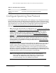
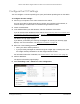
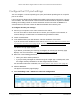
Table Of Contents
- 24-Port and 48-Port Gigabit Ethernet PoE+ Smart Switches with 4 SFP Ports
- Contents
- 1 Get Started
- Available publications
- Switch management options and default management mode
- Manage the switch by using the device UI
- About on-network and off-network access
- Access the switch on-network and connected to the Internet
- Use se a Windows-based computer to access the switch on-network and connected to the Internet
- Use the NETGEAR Insight mobile app to discover the IP address of the switch
- Use the NETGEAR Switch Discovery Tool to discover the switch when it is connected to the Internet
- Discover the switch in a network with a DHCP server using the Smart Control Center
- Use other options to discover the switch IP address
- Access the switch on-network when you know the switch IP address
- Access the switch off-network and not connected to the Internet
- Credentials for the device UI
- Register the switch
- Change the language of the device UI
- Change the management mode of the switch
- Use the Device View of the device UI
- Configure interface settings
- Access the NETGEAR support website
- Access the user manual online
- 2 Configure System Information
- View or define system information
- Configure the IP network settings for management access
- Configure the time settings
- Configure denial of service settings
- Configure DNS settings
- Configure green Ethernet settings
- Use the Device View
- Configure Power over Ethernet
- Configure SNMP
- Configure Link Layer Discovery Protocol
- Configure a DHCP L2 relay
- Configure DHCP snooping
- Configure Dynamic ARP Inspection
- Set up PoE timer schedules
- 3 Configure Switching
- Configure the port settings and maximum frame size
- Configure link aggregation groups
- Configure VLANs
- Configure a voice VLAN
- Configure Auto-VoIP
- Configure Spanning Tree Protocol
- Configure multicast
- Manage IGMP snooping
- Configure IGMP snooping
- Configure IGMP snooping for interfaces
- View, search, or clear the IGMP snooping table
- Configure IGMP snooping for VLANs
- Modify IGMP snooping settings for a VLAN
- Disable IGMP snooping on a VLAN and remove it from the table
- Configure one or more IGMP multicast router interfaces
- Configure an IGMP multicast router VLAN
- IGMP snooping querier overview
- Configure an IGMP snooping querier
- Configure an IGMP snooping querier for VLANs
- Display the status of the IGMP snooping querier for VLANs
- Manage MLD snooping
- Enable MLD snooping
- Configure MLD snooping for interfaces
- Configure the MLD VLAN settings
- Modify the MLD snooping settings for a VLAN
- Remove MLD snooping from a VLAN
- Configure one or more MLD multicast router interfaces
- Configure an MLD multicast router VLAN
- Configure an MLD snooping querier
- Configure the MLD snooping querier VLAN settings
- Configure multicast VLAN registration
- View, search, and manage the MAC address table
- Configure Layer 2 loop protection
- 4 Configure Routing
- 5 Configure Quality of Service
- 6 Manage Device Security
- Change the device admin password for the device UI
- Manage the RADIUS settings
- Configure the TACACS+ settings
- Configure authentication lists
- Manage the Smart Control Center
- Configure management access
- Control access with profiles and rules
- Configure port authentication
- Set up traffic control
- Configure access control lists
- Use the ACL Wizard to create a simple ACL
- Configure a MAC ACL
- Configure MAC ACL rules
- Configure MAC bindings
- View or delete MAC ACL bindings in the MAC binding table
- Configure a basic or extended IPv4 ACL
- Configure rules for a basic IPv4 ACL
- Configure rules for an extended IPv4 ACL
- Configure an IPv6 ACL
- Configure rules for an IPv6 ACL
- Configure IP ACL interface bindings
- View or delete IP ACL bindings in the IP ACL binding table
- Configure VLAN ACL bindings
- 7 Monitor the Switch and the Traffic
- 8 Maintain or Troubleshoot the switch
- A Configuration Examples
- B Specifications and Default Settings

24-Port and 48-Port Gigabit Ethernet PoE+ Smart Switches with 4 SFP Ports
Configure Switching User Manual193
Configure Spanning Tree Protocol
The Spanning Tree Protocol (STP) provides a tree topology for any arrangement of network
devices. STP also provides one path between end stations on a network, eliminating loops.
STP (also referred to as “classic” STP) provides a single path between end stations, avoiding
and eliminating loops. For information about configuring the global STP settings for the
switch, see
Configure the STP settings and view the STP status on page 194.
The switch support the following spanning tree versions:
• CST. Common STP
. For information on configuring CST, see Configure the CST Settings
on page 196 and Configure the CST port settings on page 198.
• MSTP. Multiple Spanning
Tree Protocol (MSTP, also referred to as MST) supports
multiple instances of spanning tree to efficiently channel VLAN traffic over different
interfaces. For information on configuring MSTP, see
Manage the MST settings on
page 203 and Configure and view the port settings for an MST instance on page 206.
• RSTP. Rapid STP
. Each instance of the spanning tree behaves in the manner specified in
IEEE 802.1w, Rapid Spanning Tree (RSTP), with slight modifications in the working but
not the end effect (chief among the effects is the rapid transitioning of the port to the
forwarding state). For information on viewing the RSTP state, see
View the Rapid STP
information on page 202.
The difference between the RSTP and the traditional STP (IEEE 802.1D) is the ability to
configure and recognize full-duplex connectivity and ports that are connected to end
stations, resulting in rapid transitioning of the port to the forwarding state and the
suppression of
Topology Change Notification. These features are represented by the
parameters pointtopoint and edgeport. MSTP is compatible with both RSTP and STP. It
behaves in a way that is appropriate for STP and RSTP bridges. An MSTP bridge can be
configured to behave entirely as an RSTP bridge or an STP bridge.
Note: For two bridges to be in the same region, the force version must be
802.1s and their configuration names, digest keys, and revision levels
must match. For additional information about regions and their effect
on network topology, refer to the IEEE 802.1Q standard.
Number of Voice Channels
Detected
The number of VoIP channels prioritized successfully.
Table 34. Auto-VoIP status (continued)
Field Description