
User Manual


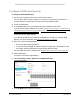


Table Of Contents
- 24-Port Gigabit (Hi-Power) PoE+ Ethernet Smart Managed Pro Switch with 2 SFP Ports and Cloud Management
- Contents
- 1 Get Started
- Available publications
- Switch management options and default management mode
- Manage the switch by using the device UI
- About on-network and off-network access
- Access the switch on-network and connected to the Internet
- Use a Windows-based computer to access the switch on-network and connected to the Internet
- Use the NETGEAR Insight mobile app to discover the IP address of the switch
- Use the NETGEAR Switch Discovery Tool to discover the switch when it is connected to the Internet
- Discover the switch in a network with a DHCP server using the Smart Control Center
- Use other options to discover the switch IP address
- Access the switch on-network and connected to the Internet when you know the switch IP address
- Access the switch off-network and not connected to the Internet
- Credentials for the device UI
- Register the switch
- Change the language of the device UI
- Change the management mode of the switch
- Use the Device View of the device UI
- Configure interface settings
- Access the NETGEAR support website
- Access the user manual online
- 2 Configure System Information
- View or define switch system information
- Configure the switch IP address settings
- Configure the IPv6 network interface
- Configure the time settings
- Configure Denial of Service settings
- Configure the DNS settings
- Configure Green Ethernet settings
- Manage switch discovery with UPnP and SSDP
- Use the Device View
- Configure Power over Ethernet
- Configure SNMP
- Configure LLDP
- Configure DHCP snooping
- Set up PoE timer schedules
- 3 Configure Switching
- Configure the port settings and maximum frame size
- Configure link aggregation groups
- Configure VLANs
- Configure a voice VLAN
- Configure Auto-VoIP
- Configure Spanning Tree Protocol
- Configure multicast
- Manage IGMP snooping
- Configure IGMP snooping
- Configure IGMP snooping for interfaces
- View, search, or clear the IGMP snooping table
- Configure IGMP snooping for VLANs
- Modify IGMP snooping settings for a VLAN
- Disable IGMP snooping on a VLAN
- Configure one or more IGMP multicast router interfaces
- Configure an IGMP multicast router VLAN
- IGMP snooping querier overview
- Configure an IGMP snooping querier
- Configure an IGMP snooping querier for a VLAN
- Display the status of the IGMP snooping querier for VLANs
- View, search, and manage the MAC address table
- Configure Layer 2 loop protection
- 4 Configure Quality of Service
- 5 Manage Device Security
- Change the device admin password for the device UI
- Manage the RADIUS settings
- Configure the TACACS+ settings
- Manage the Smart Control Center
- Configure management access
- Control access with profiles and rules
- Configure port authentication
- Set up traffic control
- Configure access control lists
- Use the ACL Wizard to create a simple ACL
- Configure a MAC ACL
- Configure MAC ACL rules
- Configure MAC bindings
- View or delete MAC ACL bindings in the MAC binding table
- Configure a basic or extended IPv4 ACL
- Configure rules for a basic IPv4 ACL
- Configure rules for an extended IPv4 ACL
- Configure an IPv6 ACL
- Configure rules for an IPv6 ACL
- Configure IP ACL interface bindings
- View or delete IP ACL bindings in the IP ACL binding table
- Configure VLAN ACL bindings
- 6 Monitor the System
- 7 Maintain or Troubleshoot the Switch
- A Configuration Examples
- B Specifications and Default Settings

24-Port Gigabit (Hi-Power) PoE+ Ethernet Smart Managed Pro Switch with 2 SFP Ports
Configure Switching User Manual146
8. In the Group Operation menu, select one of the following options, which applies to all ports
in the VLAN:
• Untag All. For all ports and LAGs that are members of the VLAN, tags are removed
from all egress packets.
• Tag All. For all
ports and LAGs that are members of the VLAN, all egress packets are
tagged.
• Remove All. All ports and LAGs are removed from the VLAN, including the p
orts and
LAGs that were dynamically registered through GVRP.
9. In the Ports table, click each port once, twice, or three times to
configure one of the following
modes or reset the port to the default settings:
• T (Tagged). Selects the port as a tagged port in the VLAN.
All frames transmitted on
the port are tagged for this VLAN.
• U (Untagged)
. Selects the port as an untagged port in the VLAN. All frames
transmitted on the port are untagged for this VLAN.
• Blank
. The port is excluded from the VLAN.
10. In the LAG table, click each LAG once, twice, or three times to configure one of the following
modes
or
reset the LAG to the default settings:
• T (Tagged).
Selects the
LAG as a tagged LAG in the VLAN. All frames transmitted on
the LAG are tagged for this VLAN.
• U (Untagged). Selects the LAG as an untagged LAG in the VLAN. All frames
transmitted on the LAG are untagged for this VLAN.
• Blank
. The LAG is excluded from the VLAN.
11. Click the Apply
button.
Your settings are saved.
The following table describes the nonconfigurable information on the page.
Table 23. Advanced VLAN membership
Field Definition
VLAN Name The name for the VLAN that you selected. It can be up to 32 alphanumeric characters long,
including blanks. The names for the following VLANs are predefined:
VLAN
Type The type of the VLAN you selected:
• VLAN 1.
Default.
• VLAN
4088. Auto-VoIP.
• Default (VLAN ID
= 1). Always present.
• Static. A VLAN that you configured.
• Dynamic. A VLAN that is created through GVRP registration, that you did not convert to
a static VLAN, and that GVRP can therefore remove.