
User Manual


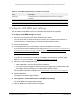
Table Of Contents
- 24-Port Gigabit (Hi-Power) PoE+ Ethernet Smart Managed Pro Switch with 2 SFP Ports and Cloud Management
- Contents
- 1 Get Started
- Available publications
- Switch management options and default management mode
- Manage the switch by using the device UI
- About on-network and off-network access
- Access the switch on-network and connected to the Internet
- Use a Windows-based computer to access the switch on-network and connected to the Internet
- Use the NETGEAR Insight mobile app to discover the IP address of the switch
- Use the NETGEAR Switch Discovery Tool to discover the switch when it is connected to the Internet
- Discover the switch in a network with a DHCP server using the Smart Control Center
- Use other options to discover the switch IP address
- Access the switch on-network and connected to the Internet when you know the switch IP address
- Access the switch off-network and not connected to the Internet
- Credentials for the device UI
- Register the switch
- Change the language of the device UI
- Change the management mode of the switch
- Use the Device View of the device UI
- Configure interface settings
- Access the NETGEAR support website
- Access the user manual online
- 2 Configure System Information
- View or define switch system information
- Configure the switch IP address settings
- Configure the IPv6 network interface
- Configure the time settings
- Configure Denial of Service settings
- Configure the DNS settings
- Configure Green Ethernet settings
- Manage switch discovery with UPnP and SSDP
- Use the Device View
- Configure Power over Ethernet
- Configure SNMP
- Configure LLDP
- Configure DHCP snooping
- Set up PoE timer schedules
- 3 Configure Switching
- Configure the port settings and maximum frame size
- Configure link aggregation groups
- Configure VLANs
- Configure a voice VLAN
- Configure Auto-VoIP
- Configure Spanning Tree Protocol
- Configure multicast
- Manage IGMP snooping
- Configure IGMP snooping
- Configure IGMP snooping for interfaces
- View, search, or clear the IGMP snooping table
- Configure IGMP snooping for VLANs
- Modify IGMP snooping settings for a VLAN
- Disable IGMP snooping on a VLAN
- Configure one or more IGMP multicast router interfaces
- Configure an IGMP multicast router VLAN
- IGMP snooping querier overview
- Configure an IGMP snooping querier
- Configure an IGMP snooping querier for a VLAN
- Display the status of the IGMP snooping querier for VLANs
- View, search, and manage the MAC address table
- Configure Layer 2 loop protection
- 4 Configure Quality of Service
- 5 Manage Device Security
- Change the device admin password for the device UI
- Manage the RADIUS settings
- Configure the TACACS+ settings
- Manage the Smart Control Center
- Configure management access
- Control access with profiles and rules
- Configure port authentication
- Set up traffic control
- Configure access control lists
- Use the ACL Wizard to create a simple ACL
- Configure a MAC ACL
- Configure MAC ACL rules
- Configure MAC bindings
- View or delete MAC ACL bindings in the MAC binding table
- Configure a basic or extended IPv4 ACL
- Configure rules for a basic IPv4 ACL
- Configure rules for an extended IPv4 ACL
- Configure an IPv6 ACL
- Configure rules for an IPv6 ACL
- Configure IP ACL interface bindings
- View or delete IP ACL bindings in the IP ACL binding table
- Configure VLAN ACL bindings
- 6 Monitor the System
- 7 Maintain or Troubleshoot the Switch
- A Configuration Examples
- B Specifications and Default Settings

24-Port Gigabit (Hi-Power) PoE+ Ethernet Smart Managed Pro Switch with 2 SFP Ports
Configure System Information User Manual108
• To configure all interfaces with the same settings, select the check box in the heading
row.
8. Use the following menus to configure the LLDP settings for the selected ports:
•
Admin Status. Select the status for transmitting and receiving LLDP packets:
- Tx Only. Enable only transmitting LLDP PDUs on the selected ports.
- Rx Only. Enable only receiving LLDP PDUs on the selected ports.
- Tx and Rx. Enable both transmitting and receiving LLDP PDUs on the selected
ports.
- Disabled. Do not transmit or receive LLDP PDUs on the selected ports.
The default is Tx and Rx.
• Management IP Address. Choose whether to advertise the management IP address
from the interface.
The possible field values are as follows:
-
Stop Advertise. Do not advertise the management IP address from the interface.
- Auto Advertise.
Advertise the current IP address of the device as the
management IP address.
The default is
Auto Advertise.
• Notification. When
notifications are enabled, LLDP interacts with the trap manager to
notify subscribers of remote data change statistics. The default is Disable.
• Optional TLV(s). Enable or disable the transmission of optional type-length value
(TLV) information from the interface.
The default is Enable. The TLV information
includes the system name, system description, system capabilities, and port
description.
For information about how to configure the system name, see
View or define switch
system information on page 51. For information about how to configure the port
description, see
Configure the port settings and maximum frame size on page 132.
9. Click the Apply
button.
Your settings are saved.
View LLDP-MED network policy information
You can display information about the LLPD-MED network policy TLVs transmitted in the
LLDP frames on the selected local interface.
To view LLDP-MED network policy information for an interface:
1. Connect your
computer to the same network as the switch.
You can use a WiFi or wired connection to connect your computer to the network, or
connect directly to a switch that is off-network using an Ether
net cable.
2. Launch a web browser.
3. In the address field of your web browser, enter the IP address of the switch.