
User Manual

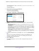

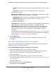
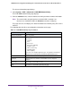


Table Of Contents
- 24-Port Gigabit Smart Managed Pro Switch with PoE+ and 2 SFP Ports Model GS724TPv2
- Contents
- 1. Get Started
- Switch Management Interface Overview
- Change the Default IP Address of the Switch
- Discover a Switch in a Network With a DHCP Server
- Discover a Switch in a Network Without a DHCP Server
- Configure the Network Settings on Your Computer
- Access the Web Browser–Based Management Interface
- About the User Interfaces
- Use a Web Browser to Access the Switch and Log In
- Web Browser–Based Management Interface Device View
- Interface Naming Conventions
- Configure Interface Settings
- Context-Sensitive Help and Access to the Support WebSite
- Register Your Product
- 2. Configure System Information
- 3. Configure Switching
- Configure Port Settings
- Configure Link Aggregation Groups
- Configure VLANs
- Configure a Voice VLAN
- Configure Auto-VoIP
- Configure Spanning Tree Protocol
- Configure Multicast
- View the MFDB Table
- View the MFDB Statistics
- IGMP Snooping Overview
- Configure IGMP Snooping
- Configure IGMP Snooping for Interfaces
- View the IGMP Snooping Table
- Configure IGMP Snooping for VLANs
- Modify IGMP Snooping Settings for a VLAN
- IGMP Snooping Querier Overview
- Configure IGMP Snooping Querier
- Configure IGMP Snooping Querier for VLANs
- Display IGMP Snooping Querier for VLAN Status
- Configure a Static Multicast Group
- Remove a Static Multicast Group
- Configure Multicast Group Membership
- Configure the Multicast Forward All Option
- View and Configure the MAC Address Table
- 4. Configure Quality of Service
- 5. Manage Device Security
- Configure the Management Security Settings
- Configure Management Access
- Configure Port Authentication
- Configure Traffic Control
- Configure Access Control Lists
- Use the ACL Wizard to Create a Simple ACL
- Configure a MAC ACL
- Configure MAC ACL Rules
- Configure MAC Bindings
- View or Delete MAC ACL Bindings in the MAC Binding Table
- Configure an IP ACL
- Configure Rules for a Basic IP ACL
- Configure Rules for an Extended IP ACL
- Configure IP ACL Interface Bindings
- View or Delete IP ACL Bindings in the IP ACL Binding Table
- 6. Monitor the System
- 7. Maintenance
- A. Configuration Examples
- B. Specifications and Default Settings

Configure System Information
74
NETGEAR 24-Port Gigabit Smart Managed Pro Switch with PoE+ and 2 SFP Ports Model GS724TPv2
- Tx and Rx. Enable both transmitting and receiving LLDP PDUs on the selected
ports.
- Disabled. Do not transmit or receive LLDP PDUs on the selected ports.
The default is Tx and Rx.
• Management IP Address. Choose whether to advertise the management IP address
from the interface. The possible field values are as follows:
- Stop Advertise. Do not advertise the management IP address from the interface.
- Auto Advertise. Advertise the current IP address of the device as the
management IP address.
The default is Auto Advertise.
• Notification. When notifications are enabled, LLDP interacts with the trap manager to
notify subscribers of remote data change statistics. The default is Disable.
• Optional TLV(s). Enable or disable the transmission of optional type-length value
(TLV) information from the interface. The default is Enable. The TLV information
includes the system name, system description, system capabilities, and port
description.
For information about how to configure the system name, see View and Configure the
Switch Management Settings on page 29. For information about how to configure the
port description, see Configure Port Settings on page 93.
8. Click the Apply button.
The updated configuration is sent to the switch. Configuration changes take effect
immediately.
View LLDP-MED Network Policy Information
You can display information about the LLPD-MED network policy TLVs transmitted in the
LLDP frames on the selected local interface.
To view LLDP-MED network policy information for an interface:
1. Connect your computer to the same network as the switch.
You can use a WiFi or wired connection to connect your computer to the network, or
connect directly to a switch that is off-network using an Ethernet cable.
2. Launch a web browser.
3. In the address field of your web browser, enter the IP address of the switch.
If you do not know the IP address of the switch, see Change the Default IP Address of the
Switch on page 9.
The login window opens.
4. Enter the switch’s password in the Password field.
The default password is password.