
User Manual


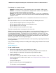

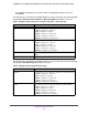


Table Of Contents
- 24-Port Gigabit Smart Managed Pro Switch with PoE+ and 2 SFP Ports Model GS724TPv2
- Contents
- 1. Get Started
- Switch Management Interface Overview
- Change the Default IP Address of the Switch
- Discover a Switch in a Network With a DHCP Server
- Discover a Switch in a Network Without a DHCP Server
- Configure the Network Settings on Your Computer
- Access the Web Browser–Based Management Interface
- About the User Interfaces
- Use a Web Browser to Access the Switch and Log In
- Web Browser–Based Management Interface Device View
- Interface Naming Conventions
- Configure Interface Settings
- Context-Sensitive Help and Access to the Support WebSite
- Register Your Product
- 2. Configure System Information
- 3. Configure Switching
- Configure Port Settings
- Configure Link Aggregation Groups
- Configure VLANs
- Configure a Voice VLAN
- Configure Auto-VoIP
- Configure Spanning Tree Protocol
- Configure Multicast
- View the MFDB Table
- View the MFDB Statistics
- IGMP Snooping Overview
- Configure IGMP Snooping
- Configure IGMP Snooping for Interfaces
- View the IGMP Snooping Table
- Configure IGMP Snooping for VLANs
- Modify IGMP Snooping Settings for a VLAN
- IGMP Snooping Querier Overview
- Configure IGMP Snooping Querier
- Configure IGMP Snooping Querier for VLANs
- Display IGMP Snooping Querier for VLAN Status
- Configure a Static Multicast Group
- Remove a Static Multicast Group
- Configure Multicast Group Membership
- Configure the Multicast Forward All Option
- View and Configure the MAC Address Table
- 4. Configure Quality of Service
- 5. Manage Device Security
- Configure the Management Security Settings
- Configure Management Access
- Configure Port Authentication
- Configure Traffic Control
- Configure Access Control Lists
- Use the ACL Wizard to Create a Simple ACL
- Configure a MAC ACL
- Configure MAC ACL Rules
- Configure MAC Bindings
- View or Delete MAC ACL Bindings in the MAC Binding Table
- Configure an IP ACL
- Configure Rules for a Basic IP ACL
- Configure Rules for an Extended IP ACL
- Configure IP ACL Interface Bindings
- View or Delete IP ACL Bindings in the IP ACL Binding Table
- 6. Monitor the System
- 7. Maintenance
- A. Configuration Examples
- B. Specifications and Default Settings

Configure System Information
42
NETGEAR 24-Port Gigabit Smart Managed Pro Switch with PoE+ and 2 SFP Ports Model GS724TPv2
Configure an SNTP Server
SNTP assures accurate network device clock time synchronization up to the millisecond.
Time synchronization is performed by a network SNTP server. The switch operates only as
an SNTP client and cannot provide time services to other systems.
Time sources are established by strata. Strata define the accuracy of the reference clock. The
higher the stratum (where zero is the highest), the more accurate the clock. The device
receives time from Stratum 1 and above since it is itself a Stratum 2 device.
Last Attempt Status The status of the last SNTP request or unsolicited message for both unicast
and broadcast modes. If no message was received from a server, a status of
Other is displayed. These values are appropriate for all operational modes.
• Other. The status of the last request is unknown.
• Success. The SNTP operation was successful and the system time was
updated.
• Request Timed Out. After an SNTP request was sent to an SNTP server,
the response timer expired before a response from the server was
received.
• Bad Date Encoded. The time provided by the SNTP server is not valid.
• Version Not Supported. The SNTP version supported by the server is not
compatible with the version supported by the client.
• Server Unsynchronized. The SNTP server is not synchronized with its
peers. This is indicated by the leap indicator field in the SNTP message.
• Server Kiss Of Death. The SNTP server indicated that no further queries
were to be sent to this server. This is indicated by a stratum field equal to
0 in a message received from a server.
Server IP Address The IP address of the server for the last received valid packet. If no message
was received from any server, an empty string is shown.
Address Type The address type of the SNTP server address for the last received valid
packet.
Server Stratum The claimed stratum of the server for the last received valid packet.
Reference Clock ID The reference clock identifier of the server for the last received valid packet.
Server mode The mode of the server for the last received valid packet.
Unicast Server Max Entries The maximum number of unicast server entries that can be configured on this
client.
Unicast Server Current Entries The number of current valid unicast server entries configured for this client.
Broadcast Count The number of unsolicited broadcast SNTP messages that were received and
processed by the SNTP client since the last reboot.
Table 5. SNTP Global Status information (continued)
Field Description