
User Manual


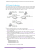


Table Of Contents
- 24-Port Gigabit Smart Managed Pro Switch with PoE+ and 2 SFP Ports Model GS724TPv2
- Contents
- 1. Get Started
- Switch Management Interface Overview
- Change the Default IP Address of the Switch
- Discover a Switch in a Network With a DHCP Server
- Discover a Switch in a Network Without a DHCP Server
- Configure the Network Settings on Your Computer
- Access the Web Browser–Based Management Interface
- About the User Interfaces
- Use a Web Browser to Access the Switch and Log In
- Web Browser–Based Management Interface Device View
- Interface Naming Conventions
- Configure Interface Settings
- Context-Sensitive Help and Access to the Support WebSite
- Register Your Product
- 2. Configure System Information
- 3. Configure Switching
- Configure Port Settings
- Configure Link Aggregation Groups
- Configure VLANs
- Configure a Voice VLAN
- Configure Auto-VoIP
- Configure Spanning Tree Protocol
- Configure Multicast
- View the MFDB Table
- View the MFDB Statistics
- IGMP Snooping Overview
- Configure IGMP Snooping
- Configure IGMP Snooping for Interfaces
- View the IGMP Snooping Table
- Configure IGMP Snooping for VLANs
- Modify IGMP Snooping Settings for a VLAN
- IGMP Snooping Querier Overview
- Configure IGMP Snooping Querier
- Configure IGMP Snooping Querier for VLANs
- Display IGMP Snooping Querier for VLAN Status
- Configure a Static Multicast Group
- Remove a Static Multicast Group
- Configure Multicast Group Membership
- Configure the Multicast Forward All Option
- View and Configure the MAC Address Table
- 4. Configure Quality of Service
- 5. Manage Device Security
- Configure the Management Security Settings
- Configure Management Access
- Configure Port Authentication
- Configure Traffic Control
- Configure Access Control Lists
- Use the ACL Wizard to Create a Simple ACL
- Configure a MAC ACL
- Configure MAC ACL Rules
- Configure MAC Bindings
- View or Delete MAC ACL Bindings in the MAC Binding Table
- Configure an IP ACL
- Configure Rules for a Basic IP ACL
- Configure Rules for an Extended IP ACL
- Configure IP ACL Interface Bindings
- View or Delete IP ACL Bindings in the IP ACL Binding Table
- 6. Monitor the System
- 7. Maintenance
- A. Configuration Examples
- B. Specifications and Default Settings

Configuration Examples
306
NETGEAR 24-Port Gigabit Smart Managed Pro Switch with PoE+ and 2 SFP Ports Model GS724TPv2
If you do not specify a root bridge and all switches are assigned the same bridge priority
value, the switch with the lowest MAC address is elected as the root bridge (see
Configure CST Settings on page 119).
5. On the CST Port Configuration page, select ports 1/0/1–1/0/8 and select Enable from the
STP Status menu (see Configure CST Port Settings on page 121).
6. Click the Apply button.
7. Select ports 1/0/1–1/0/5 (edge ports), and select Enable from the Fast Link menu.
Since the edge ports are not at risk for network loops, ports with Fast Link enabled
transition directly to the forwarding state.
8. Click the Apply button.
On the CST Port Status page you can view spanning tree information about each port.
9. On the MST Configuration page (see Manage MST Settings on page 125), create a MST
instances with the following settings:
• MST ID. 1
• Priority. Use the default (32768)
• VLAN ID. 300
For more information, see View Rapid STP Information on page 124.
10. Click the Add button.
11. Create a second MST instance with the following settings
• MST ID. 2
• Priority. 49152
• VLAN ID. 500
12. Click the Add button.
In this example, assume that Switch 1 became the root bridge for the MST instance 1, and
Switch 2 became the root bridge for MST instance 2. Switch 3 supports hosts in the sales
department (ports 1/0/1, 1/0/2, and 1/0/3) and in the HR department (ports 1/0/4 and 1/0/5).
Switches 1 and 2 also include hosts in the sales and HR departments. The hosts connected
from Switch 2 use VLAN 500, MST instance 2 to communicate with the hosts on Switch 3
directly. Likewise, hosts of Switch 1 use VLAN 300, MST instance 1 to communicate with the
hosts on Switch 3 directly.
The hosts use different instances of MSTP to effectively use the links across the switch. The
same concept can be extended to other switches and more instances of MSTP.