
User Manual


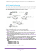


Table Of Contents
- 24-Port Gigabit Smart Managed Pro Switch with PoE+ and 2 SFP Ports Model GS724TPv2
- Contents
- 1. Get Started
- Switch Management Interface Overview
- Change the Default IP Address of the Switch
- Discover a Switch in a Network With a DHCP Server
- Discover a Switch in a Network Without a DHCP Server
- Configure the Network Settings on Your Computer
- Access the Web Browser–Based Management Interface
- About the User Interfaces
- Use a Web Browser to Access the Switch and Log In
- Web Browser–Based Management Interface Device View
- Interface Naming Conventions
- Configure Interface Settings
- Context-Sensitive Help and Access to the Support WebSite
- Register Your Product
- 2. Configure System Information
- 3. Configure Switching
- Configure Port Settings
- Configure Link Aggregation Groups
- Configure VLANs
- Configure a Voice VLAN
- Configure Auto-VoIP
- Configure Spanning Tree Protocol
- Configure Multicast
- View the MFDB Table
- View the MFDB Statistics
- IGMP Snooping Overview
- Configure IGMP Snooping
- Configure IGMP Snooping for Interfaces
- View the IGMP Snooping Table
- Configure IGMP Snooping for VLANs
- Modify IGMP Snooping Settings for a VLAN
- IGMP Snooping Querier Overview
- Configure IGMP Snooping Querier
- Configure IGMP Snooping Querier for VLANs
- Display IGMP Snooping Querier for VLAN Status
- Configure a Static Multicast Group
- Remove a Static Multicast Group
- Configure Multicast Group Membership
- Configure the Multicast Forward All Option
- View and Configure the MAC Address Table
- 4. Configure Quality of Service
- 5. Manage Device Security
- Configure the Management Security Settings
- Configure Management Access
- Configure Port Authentication
- Configure Traffic Control
- Configure Access Control Lists
- Use the ACL Wizard to Create a Simple ACL
- Configure a MAC ACL
- Configure MAC ACL Rules
- Configure MAC Bindings
- View or Delete MAC ACL Bindings in the MAC Binding Table
- Configure an IP ACL
- Configure Rules for a Basic IP ACL
- Configure Rules for an Extended IP ACL
- Configure IP ACL Interface Bindings
- View or Delete IP ACL Bindings in the IP ACL Binding Table
- 6. Monitor the System
- 7. Maintenance
- A. Configuration Examples
- B. Specifications and Default Settings

Configuration Examples
304
NETGEAR 24-Port Gigabit Smart Managed Pro Switch with PoE+ and 2 SFP Ports Model GS724TPv2
ensures that frames with a given VLAN ID are assigned to one and only one of the MSTIs or
the IST within the region, that the assignment is consistent among all the networking devices
in the region, and that the stable connectivity of each MSTI and IST at the boundary of the
region matches that of the CST. The stable active topology of the bridged LAN with respect to
frames consistently classified as belonging to any given VLAN thus simply and fully connects
all LANs and networking devices throughout the network, though frames belonging to
different VLANs can take different paths within any region, per IEEE DRAFT P802.1s/D13.
All bridges, whether they use STP, RSTP, or MSTP, send information in configuration
messages through Bridge Protocol Data Units (BPDUs) to assign port roles that determine
each port’s participation in a fully and simply connected active topology based on one or
more spanning trees. The information communicated is known as the spanning tree priority
vector. The BPDU structure for each of these different protocols is different. An MSTP bridge
transmits the appropriate BPDU depending on the received type of BPDU from a particular
port.
An MST region comprises of one or more MSTP bridges with the same MST configuration
identifier, using the same MSTIs, and without any bridges attached that cannot receive and
transmit MSTP BPDUs. The MST configuration identifier includes the following components:
1. Configuration identifier format selector
2. Configuration name
3. Configuration revision level
4. Configuration digest: 16-byte signature of type HMAC-MD5 created from the MST
Configuration Table (a VLAN ID to MSTID mapping)
Because multiple instances of spanning tree exist, an MSTP state is maintained on a
per-port, per-instance basis (or on a per-port, per-VLAN basis, as any VLAN can be in one
and only one MSTI or CIST). For example, port A can be forwarding for instance 1 while
discarding for instance 2. The port states changed since IEEE 802.1D specification.
To support multiple spanning trees, configure an MSTP bridge with an unambiguous
assignment of VLAN IDs (VIDs) to spanning trees. For such a configuration, ensure the
following:
1. The allocation of VIDs to FIDs is unambiguous.
2. Each FID that is supported by the bridge is allocated to exactly one spanning tree instance.
The combination of VID to FID and then FID to MSTI allocation defines a mapping of VIDs to
spanning tree instances, represented by the MST Configuration Table.
With this allocation we ensure that every VLAN is assigned to one and only one MSTI. The
CIST is also an instance of spanning tree with an MSTID of 0.
VIDs might be not be allocated to an instance, but every VLAN must be allocated to one of
the other instances of spanning tree.
The portion of the active topology of the network that connects any two bridges in the same
MST region traverses only MST bridges and LANs in that region, and never bridges of any
kind outside the region. In other words, connectivity within the region is independent of
external connectivity.