
User Manual
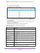


Table Of Contents
- 24-Port Gigabit Smart Managed Pro Switch with PoE+ and 2 SFP Ports Model GS724TPv2
- Contents
- 1. Get Started
- Switch Management Interface Overview
- Change the Default IP Address of the Switch
- Discover a Switch in a Network With a DHCP Server
- Discover a Switch in a Network Without a DHCP Server
- Configure the Network Settings on Your Computer
- Access the Web Browser–Based Management Interface
- About the User Interfaces
- Use a Web Browser to Access the Switch and Log In
- Web Browser–Based Management Interface Device View
- Interface Naming Conventions
- Configure Interface Settings
- Context-Sensitive Help and Access to the Support WebSite
- Register Your Product
- 2. Configure System Information
- 3. Configure Switching
- Configure Port Settings
- Configure Link Aggregation Groups
- Configure VLANs
- Configure a Voice VLAN
- Configure Auto-VoIP
- Configure Spanning Tree Protocol
- Configure Multicast
- View the MFDB Table
- View the MFDB Statistics
- IGMP Snooping Overview
- Configure IGMP Snooping
- Configure IGMP Snooping for Interfaces
- View the IGMP Snooping Table
- Configure IGMP Snooping for VLANs
- Modify IGMP Snooping Settings for a VLAN
- IGMP Snooping Querier Overview
- Configure IGMP Snooping Querier
- Configure IGMP Snooping Querier for VLANs
- Display IGMP Snooping Querier for VLAN Status
- Configure a Static Multicast Group
- Remove a Static Multicast Group
- Configure Multicast Group Membership
- Configure the Multicast Forward All Option
- View and Configure the MAC Address Table
- 4. Configure Quality of Service
- 5. Manage Device Security
- Configure the Management Security Settings
- Configure Management Access
- Configure Port Authentication
- Configure Traffic Control
- Configure Access Control Lists
- Use the ACL Wizard to Create a Simple ACL
- Configure a MAC ACL
- Configure MAC ACL Rules
- Configure MAC Bindings
- View or Delete MAC ACL Bindings in the MAC Binding Table
- Configure an IP ACL
- Configure Rules for a Basic IP ACL
- Configure Rules for an Extended IP ACL
- Configure IP ACL Interface Bindings
- View or Delete IP ACL Bindings in the IP ACL Binding Table
- 6. Monitor the System
- 7. Maintenance
- A. Configuration Examples
- B. Specifications and Default Settings

Monitor the System
267
NETGEAR 24-Port Gigabit Smart Managed Pro Switch with PoE+ and 2 SFP Ports Model GS724TPv2
- Error (3). A device error occurred, such as a port being offline.
- Warning (4). The lowest level of a device warning.
- Notice (5). Normal but significant conditions. Provides the network administrators
with device information.
- Informational (6). Provides device information.
- Debug (7). Provides detailed information about the device.
8. From the Logs to be Displayed menu, select one of the following options:
• Current Logs. The log messages for the current switch sessions are displayed. This
is the default setting.
• Previous Logs. The previous log messages are displayed, that is, the log messages
that are still in the flash memory from before the switch was rebooted.
9. Click the Apply button.
The updated configuration is sent to the switch. Configuration changes take effect
immediately.
The Total Number of Messages field shows the total number of persistent log messages
that are stored on the switch. The maximum number of persistent log messages that can
be displayed on the switch is 256.
00002 : <14> Jan 01 00:01:38 172.16.166.215-1 DHCP [75]:
dhcintf.c(1364) 5 %% DHCP gets IP address: 172.16.166.215
The previous log message example indicates a user-level message (1) with severity 6
(info) on the switch. The message is generated by component DHCP running in thread ID
75 on Jan 01 00:01:38 by line 1364 of file dhcintf.c. This is the 5th message logged.
Messages logged to a collector or relay via syslog support an identical format as the
previous log message example.
Manage the Server Log
You can allow the switch to send log messages to remote logging hosts, if you configured
any.
Configure the Local Log Server
To configure local log server:
1. Connect your computer to the same network as the switch.
You can use a WiFi or wired connection to connect your computer to the network, or
connect directly to a switch that is off-network using an Ethernet cable.
2. Launch a web browser.
3. In the address field of your web browser, enter the IP address of the switch.
If you do not know the IP address of the switch, see Change the Default IP Address of the
Switch on page 9.