
User Manual
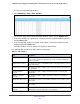


Table Of Contents
- 24-Port Gigabit Smart Managed Pro Switch with PoE+ and 2 SFP Ports Model GS724TPv2
- Contents
- 1. Get Started
- Switch Management Interface Overview
- Change the Default IP Address of the Switch
- Discover a Switch in a Network With a DHCP Server
- Discover a Switch in a Network Without a DHCP Server
- Configure the Network Settings on Your Computer
- Access the Web Browser–Based Management Interface
- About the User Interfaces
- Use a Web Browser to Access the Switch and Log In
- Web Browser–Based Management Interface Device View
- Interface Naming Conventions
- Configure Interface Settings
- Context-Sensitive Help and Access to the Support WebSite
- Register Your Product
- 2. Configure System Information
- 3. Configure Switching
- Configure Port Settings
- Configure Link Aggregation Groups
- Configure VLANs
- Configure a Voice VLAN
- Configure Auto-VoIP
- Configure Spanning Tree Protocol
- Configure Multicast
- View the MFDB Table
- View the MFDB Statistics
- IGMP Snooping Overview
- Configure IGMP Snooping
- Configure IGMP Snooping for Interfaces
- View the IGMP Snooping Table
- Configure IGMP Snooping for VLANs
- Modify IGMP Snooping Settings for a VLAN
- IGMP Snooping Querier Overview
- Configure IGMP Snooping Querier
- Configure IGMP Snooping Querier for VLANs
- Display IGMP Snooping Querier for VLAN Status
- Configure a Static Multicast Group
- Remove a Static Multicast Group
- Configure Multicast Group Membership
- Configure the Multicast Forward All Option
- View and Configure the MAC Address Table
- 4. Configure Quality of Service
- 5. Manage Device Security
- Configure the Management Security Settings
- Configure Management Access
- Configure Port Authentication
- Configure Traffic Control
- Configure Access Control Lists
- Use the ACL Wizard to Create a Simple ACL
- Configure a MAC ACL
- Configure MAC ACL Rules
- Configure MAC Bindings
- View or Delete MAC ACL Bindings in the MAC Binding Table
- Configure an IP ACL
- Configure Rules for a Basic IP ACL
- Configure Rules for an Extended IP ACL
- Configure IP ACL Interface Bindings
- View or Delete IP ACL Bindings in the IP ACL Binding Table
- 6. Monitor the System
- 7. Maintenance
- A. Configuration Examples
- B. Specifications and Default Settings

Monitor the System
265
NETGEAR 24-Port Gigabit Smart Managed Pro Switch with PoE+ and 2 SFP Ports Model GS724TPv2
The updated configuration is sent to the switch. Configuration changes take effect
immediately.
The Memory Log table displays on the Memory Log page.
The Total number of Messages field displays the number of messages the system logged
in memory. Only the 64 most recent entries are displayed on the page.
The rest of the page displays the Memory Log messages. The format of the log message
is the same for messages that are displayed for the message log, persistent log, or
console log. Messages logged to a collector or relay through syslog support the same
format as well.
The following example shows the standard format for a log message:
<14> Jan 01 01:25:47 172.16.166.215-1 HST [75]: weblogin.c(295)
7 %% HTTP Session 1 Login success from 172.16.166.231
The number contained in the angle brackets represents the message priority, which is
derived from the following values:
Priority = severity level + 8.
The facility value is usually 1, which means it is a user-level message. Therefore, to
determine the severity level of the message, add 8 to the severity level. The sample log
message shows a severity level of 6 (informational). For more information about the
severity of a log message, see Manage the Server Log on page 267.
The message was generated on Jan 01 01:25:47. The component that generated the
message is HST, and it came from line 295 of file weblogin.c. This is the 7th message
logged with system IP 172.16.166.215 and task-ID 1. The message indicates that the
administrator logged on to the HTTP management interface from a host with an IP
address of 172.16.166.231.
10. To refresh the page with the latest information about the switch, click the Update button.
11. To clear the messages from the buffered log in the memory, click the Clear button.
Message Log Format
This topic applies to the format of all logged messages that are displayed for the message
log, persistent log, or console log.
Messages logged to a collector or relay through syslog use an identical format:
<14> Jan 01 01:25:47 172.16.166.215-1 HST [75]: weblogin.c(295) 7 %%
HTTP Session 1 Login success from 172.16.166.231
The example indicates a message with severity 6 (info) on the switch and is generated by
component HST running in thread ID 75 on Jan 01 01:25:47 by line 295 of file weblogin.c.
This is the 7th message logged with system IP 172.16.166.215 and task-ID 1.